GTR 225/225A/225B Pilot’s Guide
© 2012 Garmin Ltd. or its subsidiaries. All rights reserved. This manual reflects the operation of System Software version 2.00, or later. Some differences in operation may be observed when comparing the information in this manual to later software versions. Garmin International, Inc., 1200 East 151st Street, Olathe, KS 66062, U.S.A. Tel: 913/397.8200 Fax: 913/397.8282 Garmin AT, Inc., 2345 Turner Road SE, Salem, OR 97302, U.S.A. Tel: 503/391.3411 Fax 503/364.2138 Garmin (Europe) Ltd.
LIMITED WARRANTY All Garmin avionics products are warranted to be free from defects in materials or workmanship for: two years from the date of purchase for new Remote-Mount and Panel-Mount products; one year from the date of purchase for new portable products and any purchased newly-overhauled products; six months for newly-overhauled products exchanged through a Garmin Authorized Service Center; and 90 days for factory repaired or newly-overhauled products exchanged at Garmin in lieu of repair.
WARNING: For safety reasons, GTR 225 operational procedures must be learned on the ground. CAUTION: The Garmin GTR 225 does not contain any user-serviceable parts. Repairs should only be made by an authorized Garmin service center. Unauthorized repairs or modifications could void both the warranty and the pilot’s authority to operate this device under FAA/FCC regulations.
NOTE: Canadian installations: In accordance with Canadian Radio Specifications Standard 102 (RSS 102), RF field strength exposure to persons from an antenna connected to this device should be limited to 60 V/m for controlled environment and 28 V/m for uncontrolled environment. NOTE: This device complies with Part 15 of the FCC limits for Class B digital devices.
Product Registration and Support Help us better support you by completing your online registration today! Have the serial number of your product handy and connect to the Garmin web site (www.garmin.com or https://fly.garmin.com/fly-garmin). Look for the Product Registration link on the Home page. Also, be sure to record your serial number in the space provided. If you have any questions, the Garmin Product Support department may be reached Monday through Friday, 7:00 AM to 7:00 PM Central Time.
Contents Product Registration and Support......................................................................iv 1 Getting Started.....................................................................................1-1 1.1 1.2 Product Description............................................................................... 1-1 Pilot Controls........................................................................................ 1-2 1.2.1 Power/Com Volume/Squelch Knob...................................
3.2.3 Com Database Frequencies..................................................... 3-5 3.2.4 Com Nearest Airports (APT).................................................... 3-6 3.2.5 Com Nearest Area Control Center (ACC) Frequencies.............. 3-6 3.2.6 Com Nearest Flight Service Station (FSS) Frequencies.............. 3-7 3.2.7 Com Nearest Weather (WX) Frequencies................................. 3-8 3.3 ICS Configuration.................................................................................
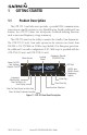
1 1.1 GETTING STARTED Product Description The GTR 225 Com Radio series provides a powerful VHF communications transceiver in a small footprint at a very affordable price. Besides traditional Com features, the GTR 225 series also incorporates workload-reducing functions such as most-used frequency storage in memory. The GTR 225 series has the ability to monitor the standby Com frequencies. The GTR 225 (10 watt) Com radio operates in the aviation voice band, from 118.000 to 136.
1.2 Pilot Controls The GTR 225 controls have been designed to simplify operation of the system and minimize workload and the time required to access sophisticated functionality. Controls are comprised of dual concentric knobs for frequency tuning, Com volume/squelch knob, and bezel keys. 1.2.1 Power/Com Volume/Squelch Knob The Power/Com Volume/Squelch knob located in the top left corner of the bezel controls audio volume for the Com radio.
1.2.2 Tuning LARGE/SMALL Concentric (Cursor) Knobs The LARGE right and SMALL right knobs are used for tuning frequencies and data entry. LARGE, Outer Knob 1.2.3 FLIP/FLOP Key 1.2.4 Press the COM key to return to the Com radio mode. MEM Key 1.2.6 Press and release the FLIP/FLOP key to switch between the active (left-most) and standby (right-most) frequency. Switching between Com frequencies is disabled while you are transmitting. Com Key 1.2.
1.2.9 FUNC (Function) Key The FUNC (Function) key accesses function categories for the following: the Com Radio, ICS Configuration, System Configuration, and Timer. Pressing the FUNC key once displays the Function mode. Pressing the FUNC key a second time exits the Function mode. 1.2.10 MON (Monitor) Key The MON (Monitor) key will engage the monitor function where the Standby frequency may be monitored while still listening to the Active frequency. 1.
2 2.1 BASIC OPERATION Power On Turn the GTR 225 on by either turning the Power/Com Volume/ Squelch knob clockwise to turn the power on or, if installed, turning on the master switch that powers the radios. 2.2 Com Radio 2.2.1 Selecting a Com Frequency New frequencies are first selected as a Standby frequency and then toggled to the Active side with the FLIP/FLOP key.
2.2.2 Monitoring the Standby Com Channel The Frequency Monitoring function allows you to monitor the Standby frequency for activity, while listening to the Active frequency. Press the MON key in the Com function to listen to the standby frequency. A small “MN” will replace the “STB” to the left of the Standby frequency.
5. Turn the LARGE knob to select the waypoint Type. 6. Turn the SMALL knob to select the Type from the list.
2.2.4 Com Database Look-Up 1. Press the CURSOR knob from the Com display to activate the database look-up function. Identifier Field Active for Selection Turn SMALL Knob To Select Character Turn LARGE Knob To Move Cursor Figure 2-5 Database Identifier Active for Selection 2. Turn the SMALL knob to select characters and turn the LARGE knob to move the cursor. Selected Identifier Figure 2-6 Database Identifier Selection 3. After selecting the desired characters, press ENT.
NOTE: Pressing and holding the Com Remote Transfer (COM RMT XFR) key for approximately two seconds, on units so configured, will lock the COM board, preventing further changes in Com frequency until the Com board is unlocked, by pressing the Com Remote Transfer key again for two seconds. The following message will notify the pilot that the Com board has been locked: “COM LOCKED TO 121.5 MHZ. HOLD REMOTE COM TRANSFER KEY TO EXIT.
This page intentionally left blank 2-6 Garmin GTR 225/225A/225B Pilot’s Guide 190-01182-00 Rev.
3 FUNCTIONS The Functions section allows provides information about Com Frequencies, Internal Communications System (ICS) Configuration, System Configuration (SYS), and Timers (TMR). 3.
1. Press the FUNC key to access the Functions. 2. Turn the LARGE knob to select the COM, ICS, or SYS functions. 3. Turn the SMALL knob to view the choices in each function. 4. Press the ENT key to access the function. 5. Press the FUNC key again to exit Functions. 3.2 Com Frequencies The Com Frequencies category in the Functions section contains recently used frequencies (Recent), user-defined frequencies (User), and a database of all frequencies provided in the standard default memory (Database). 3.2.
3.2.2 Com User Frequencies Fifteen Com User Frequencies can be saved with an assigned waypoint (WPT) identifier and Type. NOTE: When switching from 8.33 kHz to 25 kHz mode, any 8.33 kHzspecific user frequencies will be deleted from the user frequency list. This only affects the user frequencies within the 8.33 kHz spectrum. 3.2.2.1 Viewing the Com User Frequency 1. Press FUNC to access the Functions. Turn the LARGE knob to select the Com Frequency Function.
2. Press the ENT key to confirm deletion of the displayed frequency. 3.2.2.3 Editing a Com User Frequency 1. Press FUNC. Turn the LARGE knob to reach the Com functions and then turn the SMALL knob to select the Com User Frequencies. Press ENT. Select User Freqs Figure 3-5 Com User Frequency Function 2. Press the CRSR (SMALL knob) to start editing the Com User frequency. Turn the SMALL knob to select the MHz values and turn the LARGE knob to move the cursor and then the SMALL knob to select kHz values.
3.2.3 Com Database Frequencies The GTR 225 contains a large database of Com frequencies that may be recalled by identifier. Turn SMALL Knob To Select Character Turn LARGE Knob To Move Cursor Figure 3-9 Com Database Frequencies 1. Press FUNC to access the Functions. With the Com Frequency Function highlighted, turn the SMALL knob to view the Com Database function. Then, press ENT. 2. Turn the SMALL knob to select the desired character. 3. Turn the LARGE knob to move the cursor to highlight a character.
3.2.4 Com Nearest Airports (APT) The GTR 225 will report the 25 nearest Airports (APT), when interfaced with an appropriate GPS receiver. Turn SMALL Knob To Scroll Through Available Airports Figure 3-11 Com Nearest APT Frequencies 1. Press FUNC to access the Functions. With the Com Frequency Function highlighted, turn the SMALL knob to view the Com Nearest APT function. Then, press ENT. 2. Turn the SMALL knob to display the available airports. 3.
3. Press the ENT key to insert the highlighted frequency as the Standby frequency. Or, press the CLR key to return to the Functions display. 4. Press and release the FLIP/FLOP key to set the selected frequency as the Active frequency. 3.2.6 Com Nearest Flight Service Station (FSS) Frequencies The GTR 225, when interfaced with an appropriate GPS receiver, will report the 25 nearest Flight Service Station (FSS) frequencies.
3.2.7 Com Nearest Weather (WX) Frequencies The GTR 225, when interfaced with an appropriate GPS receiver, will report the 25 nearest Weather (WX) frequencies. Turn SMALL Knob To Scroll Through Available Frequencies Figure 3-14 Com Nearest Weather Frequencies 1. Press FUNC to access the Functions. With the Com Frequency Function highlighted, turn the SMALL knob to view the Com Nearest Weather function. Then, press ENT. 2. Turn the SMALL knob to display the available Weather frequencies. 3.
3.3 ICS Configuration The Internal Communications System (ICS) Configuration allows you to adjust the intercom, set the Aux Audio, turn the Intercom On/Off, and turn the speaker On/Off. 3.3.1 Adjust Intercom The Adjust Intercom function allows you to set values for the Intercom squelch and volume. The Intercom On/Off function must be set to On to make the Adjust Intercom function available. 1. Press FUNC to access the Functions. Turn the LARGE knob to select the ICS Function.
3.3.2 Aux Audio The Aux function allows you to turn Aux Audio On/Off and set the volume value. 1. Press FUNC to access the Functions. Turn the LARGE knob to select the ICS Function. Turn the SMALL knob to view the Aux Volume function. Then, press the ENT key. Figure 3-17 Select the Aux Audio Function 2. Turn the SMALL knob to turn the Aux Audio On or Off. 3. Turn the LARGE knob to select the Aux Volume. Turn the SMALL knob to set the value. Then, press the ENT key.
3.3.3 Intercom On/Off The Intercom On/Off function toggles intercom on and off. The intercom can also be toggled on/off with a remote switch, if installed. The Intercom On/ Off function must be set to On to make the Adjust Intercom function available. 1. Press FUNC to access the Functions. Turn the LARGE knob to select the ICS Function. Turn the SMALL knob to view the Intercom On/Off function. Then, press the ENT key.
3.4 System Configuration The System Configuration function will show the Software Version, Database Info, and Serial Number as well as, allowing you to set values for the Com spacing, Display Brightness, and Display Contrast, and use the Load Database feature to update databases. 3.4.1 Com Spacing Com spacing may be selected between 8.33 kHz and 25 kHz to allow for regional requirements. NOTE: When switching from 8.33 kHz to 25 kHz mode, any 8.
3.4.2 Display Brightness As it arrives from the factory, the GTR 225 automatically adjusts its display brightness for the current lighting conditions. A small sensor on the display is used for this function. A manual adjustment is available for controlling the brightness level of the display as an offset from the “normal” or zero position. The limits of the adjustment range are: -10 (Low Display Intensity) and 100 (High Display Intensity).
3.4.3 Display Contrast The Display Contrast has a range from -50 (Low Display Contrast) and 50 (High Display Contrast) with 0 as the default. The range can be adjusted by using the SMALL knob to adjust the value. 1. Press FUNC to access the Functions. Turn the LARGE knob to select the SYS Function. Turn the SMALL knob to view the Display Contrast function. Then, press the ENT key.
3.4.5 Load Database The GTR 225 has a USB connector to allow for easily updating the system databases. NOTE: Garmin recommends the use of a USB 2.0 compatible USB flash drive for updating the database. 1. Insert the supplied cable into the USB port on the top right corner of the GTR 225. 2. Insert the USB memory device into the other end of the cable. USB Port USB Cable USB Memory Device Figure 3-25 USB Update Progress 3. Press FUNC to access the Functions.
5. Wait until the updating process is complete and then remove the memory device and cable. The unit will reset automatically once the database is updated. 6. Verify the correct frequency database is loaded after power-up. 3.4.6 Software Version The software versions of the GTR 225 unit are displayed. This information is useful when contacting Customer Support. 1. Press FUNC to access the Functions. Turn the LARGE knob to select the SYS Function. 2.
3.5 Timers The GTR 225 has both Count Up and Count Down timers, which may operate simultaneously and are shown in the lower right of the Com displays. The countdown timer always takes precedence if it is running. 3.5.1 Setting Up the Count Down Timer 1. Press FUNC to access the Functions. Turn the LARGE knob to select the Timer (TMR) function. Turn the SMALL knob to select either the Count Down Timer function. Now, press the ENT key.
3.5.2 Setting Up the Count Up Timer 1. Press FUNC to access the Functions. Turn the LARGE knob to select the Timer (TMR) function. Turn the SMALL knob to select the Count Up Timer function. Now, press the ENT key. Select Count Up Timer Figure 3-32 Select the Count Up Timer Function 2. Press the ENT key to Start or Stop the timer. Press the CLR key to reset the timer to 0:00.
When the Count Down Timer reaches 0:00, it will continue counting as a Count Up value. The Count Down Timer that is counting up will be highlighted. A Count Up Timer will continue counting separately. Count Down Timer Value Highlighted When Counting Up Figure 3-36 Count Down Timer Value Now Counting Up 190-01182-00 Rev.
This page intentionally left blank 3-20 Garmin GTR 225/225A/225B Pilot’s Guide 190-01182-00 Rev.
4 APPENDIX 4.1 Troubleshooting If efforts to resolve the problem fail, contact your dealer or the factory for technical assistance. The Garmin customer service staff will gladly assist you. Please have the following information ready: • System configuration (products, antennas, mounting locations, etc.) • Model No., part number, and serial number • Software versions • Description of the problem • Efforts made to isolate/solve the problem Garmin International, Inc.
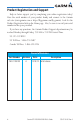
Problem GTR 225 does not power on Possible Cause No power to the GTR 225 Faulty electrical wiring or connection GTR 225 does not transmit No power to Com Mic key connection Intercom doesn’t function It can be enabled or disabled via a remote mounted switch or via the menu. No voice activation, or if must talk too loud Com Radio not communicating. The radio may also be in lockout mode. In this case the radio would be tuned to 121.50 and the active freq would not be able to be changed.
4.2 Updating the Frequency Database The GTR 225 uses a standard USB memory device to load the frequency database into the GTR 225. The memory device is not provided by Garmin. The Frequency database is stored internally and the USB memory device is only used to transfer the database into the unit. The Garmin databases can be updated by following the instructions on https://fly.garmin.com/fly-garmin.
4.3 Messages When a Message has been issued by the unit, the Message will be shown on the display. After viewing the messages, touch the ENT key to acknowledge the message and return to the previously viewed page. An acknowledged message will not be redisplayed even if the condition persists. Messages provide an aid to troubleshooting system operation. Message Press ENT To Acknowledge Figure 4-1 Message - Com PTT Key Stuck Message Description Action COM RADIO Com radio needs service.
Message Description COOLING FAN - The GTN cooling fan is The cooling fan has powered, but it is not turning at the desired failed. RPM. DISPLAY Display board needs service. POWER ALERT Unit will shut down if power switch is not restored immediately. REMOTE KEY STUCK Com push-to-talk key is stuck. REMOTE KEY STUCK Com remote transfer key is stuck. 190-01182-00 Rev. A The display board is indicating that it needs service.
Message REMOTE KEY STUCK Com remote frequency increment key is stuck. REMOTE KEY STUCK Com remote frequency decrement key is stuck. Description The remote com frequency increment (COM CHAN UP) key/ switch has been in pressed position for at least 30 seconds. This input will now be ignored. This input is not available in all installations. The remote com frequency decrement (COM CHAN DN) key/ switch has been in pressed position for at least 30 seconds. This input will now be ignored.
INDEX Functions 1-4, 3-1 A Getting started 1-1 G Appendix 4-1 Aux Audio 3-10 I B ICS 3-9 Intercom 3-11 Basic operation 2-1 Brightness 3-13 K Knobs 1-3 C Cautions ii Clear 1-3 Com database frequencies 3-5, 3-6, 3-7, 3-8 Com frequencies 3-2 Com PTT 3-12 Com radio 2-1 Com;Select frequency 2-1 Com spacing 3-12 Com user frequencies 3-3 Com volume 1-2 Contrast 3-14 Controls 1-2 Cursor 1-3 Customer service i, 4-1 D Database frequencies 3-5, 4-3 Database look-up 2-4 Display brightness 3-13 E Emergency
Stuck mic 2-5 Support iv System configuration 3-12 T Timers 3-17 Troubleshooting 4-1, 4-4 U Updating frequency database 4-3 USB 1-4, 3-15 User frequencies 3-3 W Warranty i Index-2 Garmin GTR 225/225A/225B Pilot’s Guide 190-01182-00 Rev.
© 2012 GARMIN Corporation GARMIN International, Inc. 1200 East 151st Street, Olathe, Kansas 66062, U.S.A. Tel. 913/397.8200 or 800/800.1020 Fax 913/397.8282 Garmin AT, Inc. 2345 Turner Rd., S.E., Salem, Oregon 97302, U.S.A. Tel. 503/581.8101 or 800/525.6726 Fax. 503/364.2138 Garmin (Europe) Ltd. Liberty House, Bulls Copse Road, Hounsdown Business Park, Southampton, SO40 9RB, U.K. Tel. +44 (0) 870 850 1243 Fax +44 (0) 238 052 4004 GARMIN Corporation No. 68, Zhangshu 2nd Road, Xizhi Dist.