
Installation Instructions

+ ‐ + ‐ + ‐
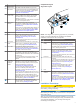
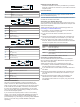
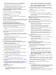
Item Description Notes
Ê
Solenoid power cable Sold separately.
Ë
Starboard solenoid
Ì
Port solenoid
Í
Bypass solenoid May not be present in all systems.
Î
Auxiliary steering system May not be present in all systems.
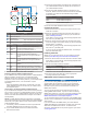
Wire Color Description
À
Red Connect to starboard solenoid positive (+).
Á
White/red Connect to starboard common (-).
Â
Black Connect to port solenoid positive (+).
Ã
White/black Connect to port common (-).
Ä
Blue Connect to bypass solenoid positive (+).
Cut and tape this wire if no bypass solenoid is
present.
Å
White/blue Connect to bypass solenoid common (-).
Cut and tape this wire if no bypass solenoid is
present.
Æ
N/A Auxiliary steering starboard positive (+) (if
present).
Ç
N/A Auxiliary steering port positive (+) (if present).
È
N/A Auxiliary steering bypass positive (+) (if present).
É
N/A Auxiliary steering common (-) (if present).
5
Connect the solenoid power cable to the ECU.
Installing a Garmin Rudder Feedback Sensor
If you installed a drive unit provided by Garmin, rudder feedback
data is provided by the drive unit, and a separate rudder
feedback sensor is not required. If you are connecting the
autopilot to a drive unit not sold by Garmin, you must also install
a rudder feedback sensor, such as the GRF 10 (sold
separately).
Follow the installation instructions provided with your GRF
rudder feedback sensor to connect it to your rudder control
and autopilot system.
Connecting to an Existing Rudder Feedback Sensor
If you connected the autopilot to a drive unit not sold by Garmin,
and you plan to connect to a rudder feedback sensor not sold by
Garmin, you must use a rudder feedback cable to connect your
sensor to the GHP Reactor Mechanical autopilot. This cable is
sold separately.
NOTE: The GHP Reactor Mechanical autopilot is compatible
with a typical three-terminal, potentiometer-type rudder feedback
sensor only. The system does not work with a frequency-based
rudder feedback sensor.
1
If necessary, use the installation instructions provided with
the rudder feedback sensor to install it on your boat.
2
If your rudder feedback sensor has cables connected,
disconnect the cables.
3
Consult the documentation provided by the manufacturer of
your rudder feedback sensor to identify the connections on
your rudder feedback sensor.
4
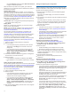
Connect the rudder feedback cable (not included) to your
drive unit, based on the wire colors and functions in the table.
If necessary, the cable can be extended using 22 AWG
(0.33 mm
2
) wire.
Wire Color Function
Red Rudder feedback positive (+)
Black Rudder feedback negative (-)
Yellow Rudder feedback wiper
5
Connect the rudder feedback cable to the ECU.
Connecting the CCU
1
Route the connector end of the CCU cable to the ECU and
make the connection.
2
Route the red and blue wires from the bare-wire portion of
the CCU cable to the location where you plan to install the
alarm (Installing the Alarm).
If the cable is not long enough, extend the appropriate wires
with 0.08 mm
2
(28 AWG) wire.
3
Route the brown and black wires from the bare-wire portion
of the CCU cable to the location where you plan to install the
Shadow Drive
™
() (optional).
If the cable is not long enough, extend the appropriate wires
with 0.08 mm
2
(28 AWG) wire.
If you do not plan to install the Shadow Drive, cut and tape
the brown and black wires.
Installing the Alarm
Before you can mount the alarm, you must select a mounting
location (Alarm Mounting and Connection Considerations).
1
Route the alarm cable to the bare-wire end of the CCU cable.
If the cable is not long enough, extend the appropriate wires
with 28 AWG (0.08 mm
2
) wire.
2
Connect the cables, based on this table.
Alarm Wire Color CCU Cable Wire Color
White (+) Red (+)
Black (-) Blue (-)
3
Solder and cover all bare-wire connections.
4
Secure the alarm with cable ties or other appropriate
mounting hardware (not included).
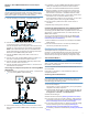
NMEA 2000 and the Autopilot Components
NOTICE
If you have an existing NMEA 2000 network on your boat, it
should already be connected to power. Do not connect the
NMEA 2000 power cable to an existing NMEA 2000 network,
because only one power source should be connected to a
NMEA 2000 network.
You can connect the helm control and the CCU through an
existing NMEA 2000 network. If you do not have an existing
NMEA 2000 network on your boat, all the parts needed to build
one are supplied in the autopilot package (Building a Basic
NMEA 2000 Network for the Autopilot System).
To use advanced features of the autopilot, optional NMEA 2000
devices, such as a GPS device, can be connected to the NMEA
2000 network.
If you are unfamiliar with NMEA 2000, you should read the
“NMEA 2000 Network Fundamentals” chapter of the Technical
Reference for NMEA 2000 Products. To download this
document, select Manuals on the product page for your device
at www.garmin.com.
6