
System Maintenance Manual


Page 7-46 G1000 / GFC 700 System Maintenance Manual - 200/B200 Series King Air
Revision 6 190-00915-01
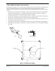
NOTE
The dial indicator shows 0.100 inch when completely flush. Therefore subtract the
readings from 0.100 inch to determine the actual static port height. This should be
completed before making any calculations.
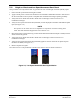
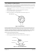
3. For each static port, measure the static port height at the A, B, C and D locations as shown in Figure
7-12. Record the measurements in the measurement log, Figure 7-13.
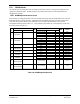
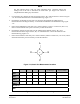
4. Calculate the AVERAGE for each static port using the measurements by adding the four
measurements and dividing the total by 4. Record the AVERAGE in the measurement log, Figure
7-13.
5. Ensure the AVERAGE for each static port is within tolerance (+0.045 to +0.085 inch.) If it is not,
remove and reinstall the static ports as necessary to meet the tolerance.
6. Calculate the ANGLE for each static port by subtracting the smallest of the A, B, C or D
measurements from the largest of the A, B, C or D measurements. Record the ANGLE in the
measurement log, Figure 7-13.
7. Ensure the ANGLE for each static port is within tolerance (0.000 to +0.026 inch.) If it is not, remove
and reinstall the static ports as necessary to meet the tolerance.
A
B
C
D
Figure 7-12, Static Port Measurement locations
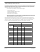
A B C D
AVERAGE
(A+B+C+D)/4
ANGLE
Largest - Smallest
UPPER
LEFT
LOWER
LEFT
UPPER
RIGHT
LOWER
RIGHT
Aircraft s/n:
Date:
Figure 7-13, Static Port Measurement Log