
System Maintenance Manual


Page 4-14 G1000 / GFC 700 System Maintenance Manual - 300/B300 Series King Air
Revision 2 190-00716-01
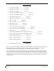
Table 4-8, Rear Fuselage and Empennage Visual Inspection Procedure
Item Description/Procedure Initials
Wi-fi Antenna
(wi-fi option only)
Inspect the external wi-fi antenna (if installed) for leading edge erosion and condition of
base seals.
Remove access panel to gain access to the tail area for the following inspections. Refer to the servo installation and equipment
tail shelf drawings and the Super King Air 300 or B300 Maintenance Manual, listed in Table 1-2.
Tail Wiring Harness
a) Inspect all exposed wire harness for chafing, damage, proper routing of wire
bundles and security of attachment in accordance with AC 43.13-1B,
Chapter 11, Section 8, Paragraph 11-96 and the Tail Wire Harness Routing
drawing, listed in Table 1-2. Pay particular attention to possible areas of
chaffing.
b) Verify security of aft bulkhead connectors
GTX 33 ( ) (Qty 2)
(GTX option only)
a) Inspect the GTX 33( ) units (if installed) and connectors for corrosion or other
defects. Check the integrity of the shield block ground attachments to the
harness connector assembly as well as the integrity of the individual shields and
their attachment.
GDL 59
(wi-fi option only)
a) Inspect the GDL 59 unit (if installed) and connectors for corrosion or other
defects. Check the integrity of the shield block ground attachments to the
harness connector assembly as well as the integrity of the individual shields and
their attachment.
GSR 56
(iridium option only)
a) Inspect the GSR 56 unit (if installed) and connectors for corrosion or other
defects. Check the integrity of the shield block ground attachments to the
harness connector assembly as well as the integrity of the individual shields and
their attachment.
GSD 41
(GSD option only)
a) Inspect the GSD 41 unit (if installed) and connectors for corrosion or other
defects. Check the integrity of the shield block ground attachments to the
harness connector assembly as well as the integrity of the individual shields and
their attachment.
GFC 700 Equipment
a) Using a flashlight, inspect the servos, servo gearboxes, attaching hardware,
connectors, support structure, and control cables to ensure that no corrosion,
chaffing, cracks, or other defects exist.
b) For pitch and pitch trim GSM 86 servo gearboxes, check that the retaining bolt
for the slip clutch cartridge is not damaged or loose.
c) For the GSM 9100 yaw servo mount, verify the two capstan retaining screws, six
drive shaft seal screws, and hole plug are tightly secured. If any of these items
are missing or loose, remove the GSM 9100 yaw servo gear box and send to a
properly rated FAA Approved Repair Station qualified for servicing of this unit.
Visually inspect the hydrophobic vent and remove any obstructions if present.
d) Have an assistant manually move the control surfaces and elevator trim wheel
from stop to stop and visually observe the corresponding servo and control
cabling. Ensure there is no binding in the control cabling, and that the capstan
rotates freely.
e) Check the servo control cables in accordance with AC 43.13-1B, Chapter 7,
Section 8, Paragraph 7-149 to ensure no fraying, corrosion, or other damage
exists. If the condition of the cable is questionable, replace it with a new one.
f) Check the tension on the control cables. Refer to the respective servo
installation drawing listed in Table 1-2 for cable tension specifications
g) Ensure that each cable is correctly attached to the clamps.
h) Follow recommended checks for checking main control cables, following the
instructions in Chapter 27, Flight Controls, of the Super King Air 300 or B300
Maintenance Manual, listed in Table 1-2.
i
)
Reinstall the access panel if no other maintenance is to be performed.
The GMU 44 units are mounted in the tailcone. To gain access, remove tailcone. Refer to Super King Air 300 or B300
Maintenance Manual, listed in Table 1-2, for removal instructions.
GMU 44 (Qty 2)
a) For each GMU 44, do the following:
b) Remove the three Phillips screws holding the GMU access plate to the mounting
bracket. Be sure to use a non-magnetic screwdriver to avoid harming the GMU.
c) Carefully remove the assembly, taking care not to damage unit or wiring, and inspect
the GMU 44 and mounting plate.
d) Inspect the mounting hardware and GMU 44 for corrosion or other damage.
e) Inspect all exposed GMU wiring and ensure no chaffing, wear, or other damage exists
in accordance with AC 43.13-1B, Chapter 11, Section 8, Paragraph 11-96 and the
Tail Wire Harness Routing drawing, listed in Table 1-2. Pay particular attention to
possible areas of chaffing.
f) Reinstall the GMU 44.