
Instruction Manual


G1000 / GFC 700 System Maintenance Manual - 300/B300 Series King Air Page 5-23
190-00716-01 Revision 3
5.2.3 Engine/Airframe Instrument Failures
The following table provides guidance for troubleshooting individual engine/airframe sensor failures. Be
sure to also follow previous guidance given for the GEA 71. The technician should troubleshoot to
isolate the fault by checking sensor-to-GEA wiring, replacing the suspect sensor, and finally by replacing
the GEA 71. Replace one part at a time. Refer to Section 7.4.1 to check for correct operation of the
sensors and GEA 71 after any part has been replaced. Refer to G1000/GFC 700 Wiring Diagram and
Super King Air 300 or B300 Maintenance Manual (listed in Table 1-2) as needed.
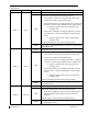
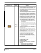
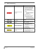
Invalid Field Sensor Possible Solutions (for applicable engine/system)
ITT
• Check thermocouple cable.
• Replace thermocouple cable.
• Replace GEA 71.
Torque
• Check torque transmitter – GEA wiring.
• Check power input to torque transmitter.
• Replace torque transmitter.
• Replace GEA 71.
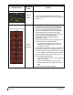
Prop RPM
•
Check prop tachometer – Signal Conditioner wiring.
• Check Signal Conditioner – GEA wiring.
• Check power input to Signal Conditioner.
• Replace prop tachometer sensor.
• Replace Signal Conditioner. Refer to Section 6.22.
• Replace GEA 71.
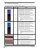
Turbine RPM
•
Check engine speed tachometer – Signal Conditioner wiring.
• Check Signal Conditioner – GEA wiring.
• Check power input to Signal Conditioner.
• Replace engine speed tachometer sensor.
• Replace Signal Conditioner. Refer to Section 6.22.
• Replace GEA 71.
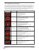
Fuel Flow
• Check Signal Conditioner unit wiring.
• Check power input to Signal Conditioner
• Replace fuel flow transmitter.
• Replace Signal Conditioner. Refer to Section 6.22.
• Replace GEA 71.
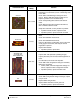
Oil Pressure
• Check oil pressure sensor – GEA wiring.
• Replace oil pressure sensor.
• Replace GEA 71.
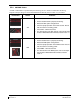
Oil Temperature
• Check oil temperature sensor – GEA wiring.
• Replace oil temperature sensor.
• Replace GEA 71.