
Instruction Manual


Page 6-16 G1000 / GFC 700 System Maintenance Manual - 300/B300 Series King Air
Revision 3 190-00716-01
Reinstallation:
1. Reinstallation of the Emergency Frequency switch/annunciator is the reverse of the removal.
Reference the Pedestal Re-Configuration drawing, listed in Table 1-2, for more details.
2. Press and hold the cockpit annunciator “Press To Test” switch located to the left of the
annunciator panel, and verify the following:
• legends illuminate and reflect “EMERG FREQ” in white and “121.5” in white.
3. Release cockpit annunciator “Press To Test” switch.
4. If further maintenance is not required, proceed to Section 8.
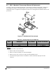
6.25 Standby Battery
Removal:
1. Gain access to the forward avionics compartment in the nose of the aircraft.
2. Unscrew the knurled hold-down nut to allow it to move free of the unit.
3. Remove the battery from the rack.
Reinstallation:
1. Install the standby battery in accordance with the Electrical Equipment Install, Nose Bay drawing
(refer to Master Drawing List, listed in Table 1-2, for specific drawing number). Refer to the
Super King Air 300 or B300 Maintenance Manual, listed in Table 1-2, for access requirements as
needed.
2. If further maintenance is not required, proceed to Section 8.
6.26 Standby Airspeed Indicator
Removal:
1. Remove MFD per Section 6.1.
2. Disconnect pitot-static plumbing from the back of the standby airspeed indicator. Take necessary
precautions to prevent foreign object debris from entering the pitot-static lines during
maintenance.
3. Disconnect the electrical connector from the standby airspeed indicator.
4. Use a Phillips screwdriver to remove the attachment screws from the front of the standby airspeed
indicator.
5. Remove the standby airspeed indicator.
Reinstallation:
1. Reinstallation of the standby airspeed indicator is the reverse of the removal. Reference the Main
Instrument Panel Installation drawing, listed in Table 1-2, for more details.
2. If further maintenance is not required, proceed to Section 8.
6.27 Standby Altimeter