
Instruction Manual


G1000 / GFC 700 System Maintenance Manual - 300/B300 Series King Air Page 6-19
190-00716-01 Revision 3
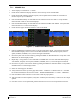
4. Reconnect the eight coax “quick-lock” connectors and the three electrical connectors.
5. Close access to the left forward avionics compartment.
6. Configure the GTS 8XX per Section 3.18 and test per Section 7.13.
6.32 GPA 65 PA/LNA Unit
Removal:
1. Remove cabin interior to access FS 158 at WL 119 on the left side of the fuselage. Reference the
Antenna Install drawing listed in Table 1-2 for more details.
2. Disconnect the eight coax “quick-lock” connectors.
3. Disconnect the electrical connector.
4. Remove the four mounting screws that hold the unit to the installation brackets.
Reinstallation:
1. Visually inspect the connectors to ensure there are no bent or damaged pins. Repair any damage.
2. Reattach the unit to the mounting brackets reusing existing hardware.
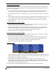
3. Connect the eight coax connectors. Note the color coded bands which match the mating
connectors on the unit.
4. Reconnect the electrical connector pigtail.
5. Ensure that all connectors (coax and electrical) are locked in place.
6. Reinstall cabin interior.
7. No configuration is required for the GPA 65. Test the GTS 8XX per Section 7.13.
6.33 GA 58 Traffic Antennas
Removal:
1. Gain access to the antenna coaxial cable connectors by removing the cabin interior ceiling panel.
Refer to the Antenna Install drawing listed in Table 1-2.
2. Disconnect the four coax “quick-lock” connectors.
3. Remove the antenna mounting screws.
4. Remove antenna.
Reinstallation:
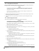
1. Install antenna using retained mounting screws.
2. Connect the four coax connectors. Note the color coded bands which match the mating
connectors.
3. Fillet seal around antenna. Refer to the Antenna Install drawing listed in Table 1-2.
4. Reinstall cabin interior ceiling panel.
5. Test the GTS 8XX according to Section 7.13.
6.34 GDL 59 Wi-Fi Datalink