
Instruction Manual


G1000 / GFC 700 System Maintenance Manual - 300/B300 Series King Air Page 3-7
190-00716-01 Revision 3
3.7 Configuration Mode Overview
Throughout this document, references are made to the PFD1, PFD2 and/or MFD being in configuration
mode. The configuration mode exists to provide the avionics technician with a means of configuring,
checking, and calibrating various G1000 sub-systems. Troubleshooting and diagnostics information can
also be viewed in this mode.
To start the G1000 system in configuration mode, follow these steps:
1. Apply external power, then set the BAT, EXT PWR and AVIONICS MASTER PWR switches to
ON.
2. Pull the MFD, PFD1 (PRI), PFD1 (SEC) and PFD2 circuit breakers.
3. Press and hold the ENT key on PFD2 (co-pilot) while applying power using the PFD2 circuit
breaker.
4. Release the ENT key after ‘INITIALIZING SYSTEM’ appears in the upper left corner of PFD2.
5. Press and hold the far right softkey on the MFD or the ENT key on the GCU 477 MFD controller
while applying power using the MFD circuit breaker.
6. Release the softkey after ‘INITIALIZING SYSTEM’ appears in the upper left corner of the
MFD.
7. Press and hold the ENT key on PFD1 (pilot) while applying power using the PFD1 (PRI) and
PFD1 (SEC) circuit breakers.
8. Release the ENT key after ‘INITIALIZING SYSTEM’ appears in the upper left corner of PFD1.
CAUTION:
The Configuration Mode contains certain pages and settings that are critical to aircraft
operation and safety. These pages are protected and cannot be modified, unless the
technician is properly authorized and equipped. However, most protected pages are
viewable to allow system awareness for troubleshooting.
NOTE
If the specific procedure requires an SD card to be in the top slot of the PFD/MFD, this
card must be inserted prior to applying power to the PFD/MFD. Any time a card is
inserted, the power to the PFD/MFD must be cycled.
NOTE
For a complete description and breakdown of each Configuration Mode page, refer to the
G1000 System Maintenance Manual listed in Table 1-3.
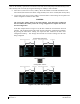
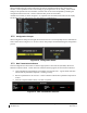
3.7.1 SET>ACTV Configuration
Throughout the configuration mode pages, there are SET and ACTIVE columns for input/output settings
and other parameters.
SET:
Refers to a setting or group of settings that reside in PFD Internal Memory and/or the Master
Configuration Module.
ACTIVE:
Refers to an ‘active’ setting or parameter currently being used by the LRU. LRUs store the
‘active’ settings within internal memory.