
System Maintenance Manual


G1000/GFC700 System Maintenance Manual – C90A/C90GT/C90GTi King Air Page 2-7
190-00682-01 Revision F
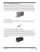
2.1.14 GSA 81 Servo, GSA 80 Servo (3) and GSM 85A/86 Servo Mount (4)
The GSA 81 (low-torque) Servo Actuator is an electromechanical unit that will provide automatic control of
pitch trim. The Garmin GSA 80 (high-torque) Servo Actuator is an electromechanical unit that will provide
pitch, roll and yaw damp and turn coordination. The GSA 80/81 contains a motor-control and monitor
circuit board, as well as a solenoid and a brushless DC motor. The GSA 80/81 servo receives serial RS-485
data packets from the GIA 63Ws. The roll servo is located in the lower fuselage at F.S. 185. The pitch, yaw,
and pitch trim servos are located in the tail. Power to the servos is received from the avionics No. 2 bus. All
servos mount to a Garmin GSM 85A (optional GSM 86) Servo Mount. The GSM 85A/86 is responsible for
transferring the output torque of the GSA 80 /81 servo actuators to the mechanical flight control surface
linkage. The GSM 85A has a slip clutch that is field serviceable and can be adjusted to the specified torque
value. The GSM 86 has a clutch cartridge that is not field serviceable, that cannot be adjusted, if the
specified torque value is not within limits the clutch cartridge must be replaced.
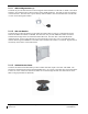
2.1.15 Comant CI428-410 / CI428-200 GPS/WAAS Antennas
The Comant CI428-410 GPS/WAAS/XM and CI428-200 GPS/WAAS antennas meet the GPS WAAS
Gamma 3 specifications required for G1000. For procedural instructions on accessing the GPS antennas,
refer to the King Air Model 90 Series Maintenance Manual listed in Table 1-2.
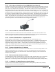
2.1.16 Thommen 5A58.22.26K.28.1 Airspeed Indicator
Either a Thommen 5A58.22.26K.28.1.ET, 5A58.22.26K.28.1.FE, 5A58.22.26K.28.1.FA or
5A58.22.26K.28.1.FP unit is installed as the standby airspeed indicator. The difference between the part
numbers is the location of the Vmca red radial; 80 KT, 85 KT and 90 KT respectively. The General
Arrangement drawing, listed in Table
1-2, contains Table 4, which shows the applicability of each part
number. The standby airspeed indicator is self illuminated and is connected to the left generator bus. The
internal lights are also connected to the emergency standby battery.
2.1.17 Thommen 3A43.22.35F.28.1.FU Altimeter
The Thommen 3A43.22.35F.28.1.FU altimeter with internal vibrator is used as the standby altimeter. The
vibrator is powered by the No. 1 triple-fed bus. This unit is self illuminated and its internal lighting is
connected to the left generator bus. Both the vibrator and the internal lighting are also connected to the
emergency standby battery.
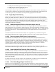
2.1.18 Mid-Continent 4200-10 Attitude Indicator
The Model 4200-10 Electric Attitude Indicator is used as the standby attitude indicator and is connected to
the No. 3 triple-fed bus. This unit is self illuminated and its internal lighting is connected to the left
generator bus. The unit along with its internal lighting is also connected to the emergency standby battery
2.1.19 L-3 PS-835(C or D Model) Emergency Standby Battery
In the event of loss of all normal electrical power, the battery is designed to provide 24 Vdc (nominal)
emergency power source for the following items: