
System Maintenance Manual


G1000/GFC700 System Maintenance Manual – C90A/C90GT/C90GTi King Air Page 4-5
190-00682-01 Revision F
4.3 Maintenance Intervals
Table 4-1 shows systems and items, installed by this STC, which must undergo tests or checks at specific
intervals. If the interval is shown to be in flight time as well as calendar months, the first interval reached
should be used as the limit.
The inspection time tables used are aligned with the existing maintenance phase intervals used in the
current King Air Model 90 Series Maintenance Manual. A complete inspection cycle for the King Air
C90 is 800 hours or 24 calendar months, divided into the following four phases:
• Inspection Phase 1: To be performed at 200 hours and every 800 hours thereafter.
• Inspection Phase 2: To be performed at 400 hours and every 800 hours thereafter.
• Inspection Phase 3: To be performed at 600 hours and every 800 hours thereafter.
• Inspection Phase 4: To be performed at 800 hours and every 800 hours thereafter.
Those inspections that are based on flight time, calendar elapsed time or cycles shall have specific
intervals stated in Table 4-1.
IMPORTANT!
As allowed in the King Air Model 90 Series Maintenance Manual, a tolerance of +/-
20 hours for all phase inspections. For tolerances on calendar months, refer to the
King Air Model 90 Series Maintenance Manual listed in Table 1-2.
The intention of Garmin is to align this maintenance program as best possible with the existing King Air
C90 inspection program. For a complete description of the King Air inspection program, refer to the
King Air Model 90 Series Maintenance Manual listed in Table 1-2.
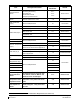
Table 4-1. Maintenance Intervals
Item Description/Procedure
Manual
Section No.
Interval
G1000/GFC700 Equipment
G1000/GFC700
System Visual
Inspections
Complete Visual Inspection of GWX 68
Equipment and Wiring located in Nose
Section
4.4
(Table 4-3)
Phase 4
Complete Visual Inspection of
G1000/GFC700 Equipment and Wiring
located in Nose Avionics Compartment
4.4
(
Table 4-4)
Phase 4
Complete Visual Inspection of
G1000/GFC700 Equipment and Wiring
located in Pilot’s Compartment
4.4
(Table 4-5)
Phase 3
Complete Visual Inspection of
G1000/GFC700 Equipment and Wiring
located on and behind Instrument Panel
4.4
(
Table 4-6)
Phase 3
Complete Visual Inspection of
G1000/GFC700 Equipment and Wiring
located in Cabin
4.4
(
Table 4-7)
Phase 3
Complete Visual Inspection of
G1000/GFC700 Equipment and Wiring
located in Rear Fuselage and Empennage
4.4
(Table 4-8)
Phase 4