
Pilot's Guide


190-00663-02 Rev. B
Garmin G1000 Pilot’s Guide for the Hawker Beechcraft C90A/GT/GTi
341
HAZARD AVOIDANCE
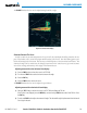
TheRANGE Knob can also be used to adjust bearing from left to right.
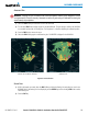
Figure 6-65 Vertical Scan Display
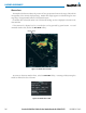
aDjUsting antenna tilt angle
Inordertomakeanaccurateinterpretationofastormcell,theradarbeamshouldbepointedatthewet
partoftheweathercelltorecordtheproperrainfallintensity(colorlevel).Theidealaimingpointisjust
belowthefreezinglevelofthestorm.ThebestwaytondthispointistousetheVerticalScanfeature.The
antenna tilt angle can be centered on the strongest return area in the vertical scan to get a more accurate
view of the coverage and intensity of the target in the horizontal scan.
Adjusting antenna tilt on the Horizontal Scan display:
1) Press the
FMS Knob to activate the cursor in the TILT field.
2) Turn the small
FMS Knob to select the desired antenna tilt angle.
3) Press the ENT Key.
4) Press the FMS Knob to remove the cursor.
TheRANGE Knob can also be used to adjust tilt up and down.
Adjusting antenna tilt on the Vertical Scan display:
1) Select the
TILT Softkey to activate the cursor in the TILT field and display the Tilt Line.
If the Tilt Line is not displayed, press the MENU Key and turn the large
FMS Knob to select Show Tilt Line. Press
the ENT Key.
2) Turn the small
FMS Knob to adjust the antenna tilt angle. The selected tilt angle is implemented when Horizontal
Scan is again selected.