
System Maintenance Manual


Page 4-16 G1000/GFC700 System Maintenance Manual – C90A/C90GT/C90GTi King Air
Revision F 190-00682-01
Pilot Compartment
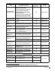
• Top metal case of PFD 1: __________ milli-volts
• Top metal case of PFD 2: __________ milli-volts
• Top metal case of MFD: __________ milli-volts
• Top metal case of GMA 1347D #1: __________ milli-volts
• Top metal case of GMA 1347D #2: __________ milli-volts
• Top metal case of GCU 475: __________ milli-volts
• Top metal case of GMC 710: __________ milli-volts
• GEA 71 #1 body: __________ milli-volts
• GEA 71 #2 body: __________ milli-volts
• GDC 74B #1 body: __________ milli-volts
• GDC 74B #2 body: __________ milli-volts
• OAT 1 Probe base nut (inside fuselage): __________ milli-volts
• OAT 2 Probe base nut (inside fuselage): __________ milli-volts
• GDL 69A body: __________ milli-volts
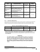
• Engine Signal Conditioner #1 near mounting holes of case: __________ milli-volts
• Engine Signal Conditioner #2 near mounting holes of case: __________ milli-volts
• PC920 Fuel Flow Signal Conditioner (
if installed) near mounting holes of case: __ ___ milli-volts
• PFD1 Cooling fan metal base: __________ milli-volts
• PFD2 Cooling fan metal base: __________ milli-volts
• MFD Cooling fan metal base: __________ milli-volts
Cabin Compartment
• GSA 80 (Roll) Servo body: __________ milli-volts
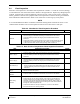
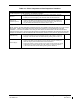
Ensure that at each PFD or MFD test point, no more than 20 milli-volts (20 mΩ) are present. Ensure that
at each other test point, no more than 2.5 milli-volts (2.5 mΩ) are present. In this case, voltage is
equivalent to resistance (Ω), given that precisely 1 amp reference current is present.
TIP: If 1 amp reference current cannot be maintained, note the difference between the attainable current
and 1 amp reference current. Calculate the percentage difference and apply this to the voltage reading to
obtain the equivalent resistance. Example: If the measured current is 1.2 amps, (20% high from the target
1 amp current), then the allowable voltage measurement would be 20% high, 2.5 milli-volts would now
be 3.0 milli-volts.