
System Maintenance Manual

Page 7-12 G1000/GFC700 System Maintenance Manual – C90A/C90GT/C90GTi King Air
Revision F 190-00682-01
VOR/LOC/GS Test
Check the VOR, ILS, and Glideslope functions with ramp test equipment. Operate the equipment
according to the test equipment manufacturer’s instructions. Adjust the RF signal to a level adequate to
perform the test. Select the appropriate HSI source by using the CDI softkey.
NOTE
The PFD HSI does not show a course deviation bar unless a valid VHF NAV frequency
is tuned.
GFC 700 VOR/LOC/GS Test
1. Ensure FD is coupled to PFD1 as indicated by a left pointing arrow next to the AFCS mode controller
XFR button.
2. Simulate a VOR signal on a radial equivalent to the aircraft heading. Tune the NAV 1 and NAV 2
receivers to the simulation frequency.
3. Set the HSI on PFD1 to VOR1 by pressing the CDI soft key until VOR1 is selected. Set the HSI on
PFD2 to VOR2 by pressing the CDI soft key until VOR2 is selected. Rotate CRS1 and CRS2 knobs
to set VOR1 and VOR2 course pointers to aircraft heading. (CDI Synchronization must be set to
OFF on the AUX-SYSTEM SETUP 1 page on the MFD.)
4. Verify full scale deflection of VOR1 and VOR2 CDI by varying CRS1 and CRS2 selected course at
least 10° left and right. Reset course pointers to aircraft heading.
5. Engage the autopilot and press the NAV key on the AFCS mode controller. Using the CRS1 knob
alter course by 10° to the right. Verify the flight director and aircraft controls respond by flying to the
VOR course. Repeat to the left.
6. Couple FD to PFD2 by pressing the XFR button on the AFCS mode controller. Verify FD is coupled
right as indicate by a right pointing arrow on the AFCS mode controller next to the XFR button.
Repeat step 5 using CRS2 knob while coupled to PFD2.
7. Set CRS1 and CRS2 course pointers to aircraft heading.
8. Simulate a Localizer/Glideslope signal. Tune this signal on NAV 1 and NAV 2 receiver. Set the
PFD1 HSI to LOC1 and PFD2 HSI to LOC2 by pressing CDI soft key until LOC1 and LOC2 is
selected. Use the test equipment to center the deviation bars (localizer and glideslope) on PFD1 and
PFD2.
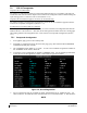
9. Press the APR key on the AFCS mode controller. Verify that the LOC and PIT annunciations are
green and ALTS and GS are white on PFD1 and PFD2. Apply right/left and up/down
localizer/glideslope signals using the test equipment. Verify that the Flight Director and flight
controls respond appropriately.
10. Couple FD to PFD1 by pressing the XFR button on the AFCS mode controller. Verify FD is coupled
to PFD1 as indicate by a left pointing arrow on the AFCS mode controller next to the XFR button.
11. Repeat step 9 using while coupled to PFD1.
12. If no other service is to be performed, continue to the return-to-service checks in Section 8.