
System Maintenance Manual

Page 7-14 G1000/GFC700 System Maintenance Manual – C90A/C90GT/C90GTi King Air
Revision F 190-00682-01
7.4.2 Additional GEA 71 Functional Tests
This section provides additional functional tests for individual GEA parameters.
7.4.2.1 Torque Functional Test
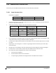
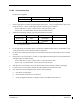
Required test equipment:
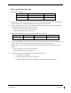
Test Equipment Make/Requirement Model/Part Nbr
Signal Generator 0-10Vdc / 0 – 1k Hz As appropriate
1. Using a signal generator, inject a DC signal into the No. 1 GEA via left engine firewall connectors-
pins J102-C (HI) and J102-R (LO).
2. Simulate the following voltages, and verify the indication and status:
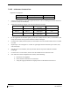
Test Point (Vdc) Indication (ft-lbs) Status Configurations
0.00 +/- .02 0
bottom of green band
Green digital
all
2.53 +/- .02 1320
red digital*
NOTE: red radial 1315
4-10
2.90 +/- .02 1525
red digital*
NOTE: red radial 1520
1-3, 14-20
3.15 +/- .02 1655
red digital*
NOTE: red radial 1650
11-13
(*) steady after 5 seconds
3. On the right hand circuit breaker panel, open the GIA1 (PRI) and GIA1 (SEC) circuit breakers, and
verify the last observed torque indication remains unchanged.
4. Close the GIA1 (PRI) and GIA1 (SEC) circuit breakers, and wait until the COM1 and NAV1 fields
are valid.
5. Repeat steps 1 and 2 using the No. 2 GEA via right engine firewall connectors-pins J103-C (HI)
and J103-R (LO).
6. Pull the GIA 2 circuit breaker, and verify the last observed torque indication remains unchanged.
7. Close the GIA 2 circuit breaker, and wait until the COM2 and NAV2 field are valid.
8. If no other tests will be completed in this section, do the following:
a. Disconnect test equipment.
b. Ensure firewall connectors are reconnected.
c. Verify all engine parameters are displayed valid on the MFD with no Red X’s.