
System Maintenance Manual


Page 2-10 G1000/GFC700 System Maintenance Manual – C90A/C90GT/C90GTi King Air
Revision F 190-00682-01
2.3 Electrical Power Distribution
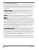
This airplane uses a multi-bus system, as detailed below and in Figures 2-1 and Figure 2-2. In normal
operation, all buses are automatically tied into a single-loop system where all sources supply power through
individual protective devices. The battery and generator switches on the pilot’s left subpanel are used to
control power from the ship battery and generators into the airplane electrical system. Switches in the
cockpit that receive power from the center and triple-fed buses are identified by a white ring on the panel
around the switch.
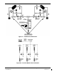
Left and Right Generator Buses:
The left and right generator buses receive power from their respective left
and right generators (ref. Figure 2-1). The left and right generator buses also support the No. 2 and No. 3
avionics buses, respectively, via the avionics master switch (ref. Figure 2-2). The No. 2 avionics bus
supplies power to the following G1000 equipment: GMA 2, GTX 2,), GWX 68, GSA 81 servos. The No. 3
avionics bus supplies power to the GDL 69(). The No. 2 and No. 3 avionics buses also supply power to
optional interface equipment.
Center Bus:
The center bus is fed by two generator buses and the hot battery bus, which automatically
connects those components whenever the bus ties are closed (ref. Figure 2-1). The center bus provides a
secondary
power source for the following G1000 equipment: PFD 1, GIA 1, GDC 1, and GRS 1.
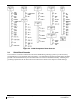
Triple-fed Bus:
The triple-fed is powered from the hot battery bus and both generator buses (ref. Figure 2-1.)
The triple-fed bus also supports avionics no.1 bus via the avionics master switch (ref. Figure 2-2). The
following G1000 equipment is supported by the triple-fed bus: MFD, PFD 1, PFD 2, GCU 475, GMC 710,
GIA 1, GIA 2, GEA 1, GEA 2, GDC 1, GDC 2, OAT, GRS 1, and GRS 2. The No. 1 avionics bus provides
power for the following G1000 equipment: GMA 1 and GTX 1. The No. 1 triple-fed bus provides power to
the No.1 Sandia Aerospace ST26 tach generator adapter, No 1 channel of the Senior Aerospace PC 920 fuel
flow conditioner, No.1 Vibro-Meter (Meggit) Signal Conditioner (if installed), and Thommen standby
altimeter vibrator (under normal conditions.) The No 2 triple-fed bus provides power to the No. 2 Sandia
Aerospace ST26 tach generator adapter, the No. 2 channel of the Senior Aerospace PC 920 fuel flow
conditioner, and the No.2 Vibro-Meter (Meggit) Signal Conditioner (if installed). The No. 3 triple-fed bus
provides power to the Mid-Continent standby attitude indicator (under normal conditions) and provides
power for charging the L-3 emergency standby battery.
Emergency Standby Battery Function:
The Standby Emergency Battery (STBY BATT) system in the King
Air C90 is designed to provide uninterrupted DC power to the Standby Attitude indicator (gyro motor) and
the Standby Altimeter (vibrator) from the L-3 PS-835(C or D Model) Emergency Standby Battery. In
addition, the STBY BATT system supplies a fixed lighting voltage to the Standby Attitude Indicator, the
Standby Altimeter, and the Standby Airspeed Indicator in the event of a total loss of DC power (ref. Figure
2-1.) For aircraft retrofitted using STC SA01456WI-D Master Drawing List (MDL) 005-00375-30, Revision
6 or later, the STBY “whiskey” compass will also receive lighting from the STBY BATT in the event of a
total loss of DC power. The STBY BATT system is a redundant power source to the Standby Attitude
indicator, Standby Altimeter, and the Standby Airspeed Indicator.
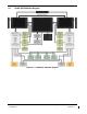
The electrical system is protected from excessively high current flow by the bus tie system. A bus tie sensor
and relay is located between each generator bus and the center bus and also between the battery bus and the
center bus. When the battery switch is on, battery bus voltage energizes and closes the relay. Similarly,
when a generator or external power is brought on-line, the generator bus tie relays are energized and closed.