
System Maintenance Manual


Page 3-6 G1000/GFC700 System Maintenance Manual – C90A/C90GT/C90GTi King Air
Revision F 190-00682-01
3.5 G1000 Normal Mode
To start the G1000 system in Normal Mode:
1. With a ground power unit connected to the external power receptacle, set the BAT and EXT
PWR switches to ‘ON’. The following G1000 equipment is powered:
• PFDs displays & MFD display
• GRS 77 AHRS Units
• GDC 74B Air Data Computers
• GIA 63W Integrated Avionics Units
• GEA 71 Engine/Airframe Units
• GCU 475 FMS Control Unit
• GMC 710 Autopilot Control Unit
2. Set the AVIONICS MASTER PWR switch to ‘ON’. The following G1000 equipment is
powered:
• GTX 33 Mode S Transponders
• GMA 1347D Digital Audio Panels
• GDL 69A Datalink Unit
• GSA Servos
• GWX 68 Weather Radar Unit
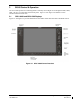
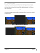
The G1000 system is now powered in the normal mode. In the normal operating mode, data fields that
are invalid have large red X’s through them. A valid field does not display a red X. Allow the displays to
initialize for approximately one minute. The GDC 74Bs requires a longer initialization period than do the
other LRUs. During normal operation, this causes the airspeed, altitude, vertical speed, and OAT fields to
be invalid during the first ~40-60 seconds of PFD power-up
. The PFDs and MFD will function as
specified in the G1000 C90A/C90GT/C90GTi Cockpit Reference Guide, when the system has been
correctly installed and configured.
Figure 3-8. Normal Mode