
System Maintenance Manual


Page 4-8 G1000/GFC700 System Maintenance Manual – C90A/C90GT/C90GTi King Air
Revision F 190-00682-01
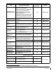
Item Description/Procedure
Manual
Section No.
Interval
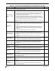
PFD, MFD, and GIA
Cooling Fans (Qty 5)
Removal & Replacement
Refer to Master Drawing List, listed in Table
1-2, for installation drawings.
N/A
G1000 Lightning Protection
Electrical Bonding
Test
Perform the Phase 3 electrical bonding
resistance check of G1000 equipment
4.5.3 Phase 3
Perform the Phase 4 electrical bonding
resistance check of G1000 equipment
4.5.4 Phase 4
Lightning Strike to
GTP 59 OAT Probe
or Antenna
Actual or Suspected
Inspect the antenna/probe and surrounding
installation per Table 4-9.
4.4 On Condition
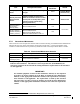
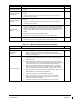
Engine/Airframe Sensors
ITT Thermocouple
Cable (Qty 2)
Removal & Replacement:
Refer to King Air Model 90 Series
Maintenance Manual listed in Table 1-2.
N/A On Condition
Oil Pressure Sensor
(Qty 2)
Oil Temperature
Sensor (Qty 2)
Torque Transmitter
(Qty 2)
Fuel Flow Transmitter
(Qty 2)
Removal & Replacement:
Refer to King Air Model 90 Series
Maintenance Manual listed in Table 1-2.
N/A
On Condition
Prop Tachometer
(Qty 2)
Engine Speed
Tachometer (Qty 2)
Engine Signal
Conditioners (Qty 2)
Removal & Replacement
6.19
Aerospace Optics
Annunciator – Prop
Sync
6.21
PC920 Conditioner (if
added by this STC)
6.20
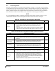
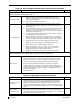
Other Equipment
Thommen Airspeed
Indicator - Standby
Removal & Replacement 6.23 On Condition
Thommen Altimeter –
Standby
Removal & Replacement 6.24 On Condition
Test according to 14 CFR 91.411 and
Part 43 Appendix E.
N/A 24 Calendar Months
Mid-Continent
Attitude Indicator –
Standby
Removal & Replacement 6.25 On Condition
L-3 PS-835(C or D
Emergency Battery
Removal & Replacement 6.22 On Condition
Capacity test of standby battery 4.16.2 12 Calendar Months