G500H Cockpit Reference Guide
© 2011-2012 Garmin Ltd. or its subsidiaries. All rights reserved. This manual reflects the operation of system software version 6.00 or later. Some differences in operation may be observed when comparing the information in this manual to later software versions. Garmin International, Inc., 1200 East 151st Street, Olathe, KS 66062, U.S.A. Tel: 913.397.8200 Fax: 913.397.8282 Garmin AT, Inc., 2345 Turner Road SE, Salem, OR 97302, U.S.A. Tel: 503.391.3411 Fax 503.364.2138 Garmin (Europe) Ltd.
AVIATION LIMITED WARRANTY All Garmin avionics products are warranted to be free from defects in materials or workmanship for: two years from the date of purchase for new Remote-Mount and Panel-Mount products; one year from the date of purchase for new portable products and any purchased newly-overhauled products; six months for newly-overhauled products exchanged through a Garmin Authorized Service Center; and 90 days for factory repaired or newly-overhauled products exchanged at Garmin in lieu of repair.
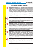
WARNINGS, CAUTIONS, AND NOTES Warnings, Cautions, & Notes WARNING: Navigation and terrain separation must NOT be predicated WARNINGS, CAUTIONS, AND NOTES upon the use of the terrain function. The G500H Terrain Proximity feature is NOT intended to be used as a primary reference for terrain avoidance and does not relieve the pilot from the responsibility of being aware of surroundings during flight.
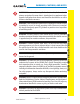
WARNINGS, CAUTIONS, AND NOTES WARNING: Do not use basemap (land and water data) information for primary navigation. Basemap data is intended only to supplement other approved navigation data sources and should be considered as an aid to enhance situational awareness. WARNING: Traffic information shown on the G500H Multi-Function Display is provided as an aid in visually acquiring traffic. Pilots must maneuver the aircraft based only upon ATC guidance or positive visual acquisition of conflicting traffic.
WARNINGS, CAUTIONS, AND NOTES WARNING: Because of anomalies in the earth’s magnetic field, operating the G500H within the following areas could result in loss of reliable attitude and heading indications. North of 65° North latitude between longitude 75° West and 120° West. An area North of 70° North latitude between longitude 70° West and 128° West. An area of North of 70° North latitude between longitude 85° East and 114° East.
WARNINGS, CAUTIONS, AND NOTES NOTE: All visual depictions contained within this document, including screen images of the G500H bezel displays, are subject to change and may not reflect the most current G500H system. Depictions of equipment may differ slightly from the actual equipment. NOTE: This device complies with part 15 of the FCC Rules.
Record of Revisions Part Number Revision 190-01150-03 A B C vi Date Jan 2010 Mar 2010 Nov 2010 D Aug 2011 E Jan 2012 Description Production Release Updated speed tape markings. Update to reflect v4.00 and v5.00 software functionality. Update to reflect v6.00 software functionality. Minor edits.
TABLE OF CONTENTS Contents Warnings, Cautions, & Notes ............................................................................ ii Introduction...................................................................................................... 1 Additional Features ........................................................................................ 16 Garmin Terrain-HSVT™ (Optional) ...............................................................................................
TABLE OF CONTENTS TABLE OF CONTENTS External Video Page (Optional) ................................................................................................... 39 System Setup Page .................................................................................................................... 40 XM® Information Page (Optional) .............................................................................................. 44 XM® Radio Page (Optional) ..............................................
PRIMARY FLIGHT DISPLAY (PFD) Introduction PFD/MFD NOTE: Some G500Hs have the right-side display configured as the PFD. 190-01150-03 Rev E G500H Cockpit Reference Guide 1 PRIMARY FLIGHT DISPLAY This reference guide covers the operation of the GDU 620 as integrated in the G500H Avionics Display System. The G500H Avionics Display System is an avionics suite that combines primary flight instrumentation, navigational information, and a moving map all displayed on dual 6.5 inch color screens.
PRIMARY FLIGHT DISPLAY (PFD) Primary Flight Display (PFD) 1 19 2 18 20 PRIMARY FLIGHT DISPLAY 17 3 16 4 15 14 12 5 6 7 8 9 10 11 13 Primary Flight Display (PFD) 2 1 NAV Status Bar: Displays which GPS is selected as the Active Source, Active Waypoint (WPT), Distance to Waypoint (DIS), Desired Track (DTK) and Current Track (TRK).
PRIMARY FLIGHT DISPLAY (PFD) Attitude Sync Soft Key: Allows the synchronization of the aircraft to the horizon in level flight. 6 Heading Select Key: Press HDG and turn PFD knob to set heading bug. 7 Course Select Key: Press CRS and turn PFD knob to set the course of the selected source (VOR1, VOR2, GPS1, or GPS2). 8 Altitude Select Key: Press ALT and turn PFD knob to set altimeter bug. 9 V/S (Vertical Speed) Select Key: Press V/S and turn PFD knob to set V/S bug.
PRIMARY FLIGHT DISPLAY (PFD) Airspeed Tape The upper left portion of the PFD display provides Groundspeed, Airspeed Trend, Current Airspeed, and True Airspeed information. Current Airspeed is normally shown in white on the black pointer. The Trend Indicator (magenta line) indicates what the airspeed will be in six seconds, if the current acceleration is maintained. If the current acceleration will cause the airspeed to exceed VNE in six seconds, the airspeed is displayed in yellow.
PRIMARY FLIGHT DISPLAY (PFD) Altitude Tape The upper right portion of the PFD displays the Altitude Bug setting, Current Altitude, Altitude Trend, Altitude Minimums Bug, and the current BARO Setting. The Altitude Trend indicates what the altitude will be in six seconds if the current vertical speed is maintained.
PRIMARY FLIGHT DISPLAY (PFD) PRIMARY FLIGHT DISPLAY Minimums Bug (Barometric or Radar Altimeter) For altitude awareness, an Altitude Minimums Bug commonly referred to as the Minimums Bug, can be set. the source of data for minimums alerting can be selected to either barometric altitude or radar altitude (if installed.) When active and within 2500 feet of the selected minimums altitude, the minimums bug setting is displayed to the bottom left of the altimeter.
PRIMARY FLIGHT DISPLAY (PFD) To set the altitude for the Minimums Bug: 1) While viewing the Active Flight Plan page of the FPL Group, press the small MFD knob to activate the cursor. 2) Turn the large MFD knob to the ALTITUDE portion of the MINIMUMS section. 3) Turn the small MFD knob to enter the desired altitude. Press the ENT key to confirm selection. 4) When finished, press the small MFD knob to exit the MINIMUMS box. The Minimums Bug can also be set from the Charts page of the FPL.
PRIMARY FLIGHT DISPLAY (PFD) Altitude Bug The Altitude Bug is displayed on the Altitude Tape at the selected altitude bug setting. A portion of the Altitude Bug will be displayed at the top or bottom of the altitude tape if the selected altitude bug is off of the tape. Altitude Bug Setting PRIMARY FLIGHT DISPLAY Altitude Bug Altitude Bug The Altitude Bug provides visual and aural altitude alerting.
PRIMARY FLIGHT DISPLAY (PFD) Wind Vectors The PFD will display a Wind Vector Field to the left of the HSI when configured by the user. There are four different styles of wind vector displays available. Refer to the System Setup page in the AUX Group section of this guide for instructions on selecting wind vector style. Wind Vectors can only be calculated when the aircraft is in the air. When airspeed is less than 20 knots, the Wind Vector windows will indicate, “No Wind Data”.
PRIMARY FLIGHT DISPLAY (PFD) Vertical Deviation Indicator (VDI) The Vertical Deviation Indicator is displayed for GPS and ILS approaches with vertical guidance. The GPS approach glidepath is shown in magenta (G and indicator), while the ILS approach glideslope is shown in green (G and indicator.
PRIMARY FLIGHT DISPLAY (PFD) Attitude Indicator Ground/Sky Pointer mode is configured during installation and can not be changed by the pilot. In an aircraft with an Attitude Indicator that has a Ground Pointer, the pointer above the roll scale shifts with the roll or bank angle of the aircraft to keep the Roll Scale Zero Pointer pointing towards the ground.
PRIMARY FLIGHT DISPLAY (PFD) The Trim Ball Indicator is the bar beneath the roll pointer. The indicator moves with the roll pointer and moves laterally away from the pointer to indicate lateral acceleration. Trim is indicated by the location of the bar relative to the pointer. One bar displacement as shown below is equivalent to one ball displacement on a traditional Trim Ball Indicator.
PRIMARY FLIGHT DISPLAY (PFD) Adjusting the Course Pointer Press the CRS key and turn the PFD knob to select a course for a VOR/ILS or OBS mode course. HSI Bearing Pointers NOTE: The Bearing Pointer for navigation source 1 (BRG1) will be an arrow with a single line. The Bearing Pointer for navigation source 2 (BRG2) will be an arrow with a double line.
PRIMARY FLIGHT DISPLAY (PFD) GPS1 GPS2 VOR1 VOR2 LOC1 LOC2 PRIMARY FLIGHT DISPLAY MSG LOI CDI Source GPS Mode GPS Advisory LOI Suspend OCN ENR TERM APR LNAV LNAV+ LPV LNAV/VNAV LP OBS SUSP PFD HSI Annunciations CDI Source The CDI Source on the HSI will display which navigation source is selected. Navigation sources available: GPS1, VOR1, or LOC1. Navigation sources available: GPS2, VOR2, or LOC2, if a second source is available.
PRIMARY FLIGHT DISPLAY (PFD) Switching Between Navigation Sources VLOC NAVIGATOR 1 GPS NAVIGATOR 2 VLOC NAVIGATOR 2 CDI Sources The Course Deviation Indicator (CDI) can display two sources of navigation: GPS or NAV (VOR or LOC). Press the CDI soft key to toggle between the available CDI modes, (GPS or VOR). If a second GPS source or NAV source is available, pressing the 1 - 2 soft key will toggle the navigation sources (VOR1 and VOR2, or GPS1 and GPS2).
PRIMARY FLIGHT DISPLAY (PFD) Additional Features Garmin Terrain-HSVT™ (Optional) Garmin Terrain-HSVT is offered as an optional feature to the G500H. HSVT is primarily comprised of a computer-generated forward-looking, attitude aligned view of the topography immediately in front of the aircraft from the pilot’s perspective. HSVT information is shown on the PFD. HSVT offers a three-dimensional view of terrain and obstacles.
PRIMARY FLIGHT DISPLAY (PFD) The following features are part of the Terrain-HSVT system. For more details refer to the latest revision of the G500H Pilot’s Guide, 190-01150-02. • Flight Path Marker • Airport Signs • Horizon Heading Marks • Runway Display • Terrain/Obstacle Display and Alerting • Water • Three-dimensional Traffic • Zero-Pitch Line NOTE: Terrain-HSVT may be deactivated under certain conditions, such as loss of heading.
MULTI-FUNCTION DISPLAY (MFD) Multi-Function Display (MFD) 1 2 7 3 MULTI-FUNCTION DISPLAY 5 6 4 Multi-Function Display (MFD) 1 Menu: Displays configuration items for each page of the page groups. 2 Clear: Erases information, cancels entries, or removes page menus. Pressing and holding the CLR key displays the first page of the Map Group. 3 Enter: Validates or confirms a menu selection or data entry. 4 Soft Keys 5 Large MFD Knob: Use to move between page groups.
MULTI-FUNCTION DISPLAY (MFD) Page Navigation - Moving Between Pages Page Group Turn Large MFD knob Page Turn Small MFD knob 1) Turn the large MFD knob to move between page groups. 2) Turn the small MFD knob to change pages within the page group. NOTE: Page Group and Page are shown at the bottom of the MFD. 1) Press the MENU key and make the necessary adjustments with the large MFD knob and small MFD knobs. 2) Press the small MFD knob to activate editing.
MULTI-FUNCTION DISPLAY (MFD) MFD Soft Key Map The soft keys available depend on the page displayed and the features available. The soft key “Alerts” is present on the far right position on all MFD pages.
MAP GROUP Map Group Navigation Map 1 and Navigation Map 2 Pages Soft Keys Found on Navigation Map Pages NOTE: Panning can be used in Terrain pages to view elevation levels. 1) While viewing Navigation Map 1 or Navigation Map 2 of the Map Page Group, press the small MFD knob. A flashing arrow (map pointer) will appear in the center of the map page. 2) Turn the large MFD knob to move the map pointer left and right (horizontally).
MAP GROUP Decluttering (DCLTR) the Map Pages MAP GROUP: NAV PAGES There are four levels of decluttering, DCLTR, DCLTR-1, DCLTR-2, and DCLTR-3. DCLTR shows the most detail while DCLTR-3 removes most detail. While viewing Navigation Map 1 or Navigation Map 2 page of the Map Page Group, press the DCLTR soft key. Each successive press of the DCLTR soft key will toggle through the declutter levels.
MAP GROUP Customizing Maps 1) While viewing Navigation Map 1 or Navigation Map 2 of the Map Page Group, press the MENU key. The option, “Map Setup” option will flash. MAP GROUP: SETUP OPTIONS Map Setup Option Menu 2) Press the ENT key to enter the setup page. The selected group will be flashing. 3) Turn the small MFD knob to activate the drop down menu and to move within available groups (Map, Weather, Traffic, or Aviation).
MAP GROUP: SETUP OPTIONS MAP GROUP Map Setup Options Group Selections • Orientation (North Up, Track Up, DTK up, HDG up) • North Up At (Off to 2500 NM) • Auto Zoom (On or Off) • Land Data (On or Off) • Track Vector Length (Off to 20 mins) • Wind Vector (On or Off) • Nav Range Ring (On or Off) MAP • Topo Data (On or Off) • Topo Scale (On or Off) • TERRAIN Data (On or Off) • TERRAIN Scale (On or Off) • Obstacle Viewing Range (Off to 50 NM) • Lat/Lon Viewing Range (Off to 2500 NM) • Field of View (On or Off)
MAP GROUP Split Screen Page (Optional) Soft Keys Found on Split Screen Page External Video is an optional function that displays video provided by an externally mounted video source on the aircraft. Current Video Source Display of External Video Source Map Display External Video 2) The External Video page will show the external video on the top half of the MFD and a Navigation Map will be shown on the lower half.
MAP GROUP Traffic Map Page (Optional) MAP GROUP: TRAFFIC PAGE Soft Keys Found on Traffic Map Page Traffic Display When a traffic alert is generated by an interface traffic system, the PFD will display a traffic annunciator and the MFD will have a pop-up screen displaying the detected traffic. To remove the pop-up, press the CLR key. Press the ENT key to go to the traffic page. The traffic pop-up window will be removed when the traffic alert is no longer active.
MAP GROUP Displaying and Operating Traffic Advisory Systems (TAS) MAP GROUP: TRAFFIC PAGE Traffic Map - TAS NOTE: Depending on your traffic configuration, the OPERATE and STANDBY soft keys may not be available.
MAP GROUP 10) Press the ALT MODE soft key to change what traffic is displayed. Pressing the BELOW, NORMAL, ABOVE or UNREST soft keys will determine what traffic is displayed. The selection is shown in the Altitude mode field. The values below define what each altitude mode displays, relative to the altitude of the aircraft.
MAP GROUP TIS Traffic The Traffic Map Page is configured to show surrounding TIS traffic data in relation to the aircraft’s current position and altitude, without clutter from the basemap. Aircraft orientation on this map is always heading up unless there is no valid heading. TIS receives traffic information from ground stations, and is updated every five seconds. The G500H displays up to eight traffic targets within a 7.5-NM radius, from 3000 feet below to 3500 feet above the requesting aircraft.
MAP GROUP Terrain Page Garmin provides the following G500H terrain selections, based upon your system configuration. Soft Keys Found on Terrain Proximity Page MAP GROUP: TERRAIN PAGE Soft Keys Found on Terrain-HSVT Page WARNING: Do not use TERRAIN-HSVT information for primary terrain avoidance. TERRAIN-HSVT is intended only to enhance situational awareness. NOTE: Terrain data is not displayed when the aircraft latitude is greater than 75° North or 60° South.
MAP GROUP Viewing Terrain (without TERRAIN-HSVT) NOTE: Obstacles will be removed from the Terrain pages when range (RNG) exceeds 10 NM. While viewing the Terrain page of the Map Page Group, press the 360 or ARC soft key to select the desired view. 360 or ARC Soft Keys Aviation Data Overlay 190-01150-03 Rev E G500H Cockpit Reference Guide 31 MAP GROUP: TERRAIN PAGE Press MENU to select whether to hide or show Aviation Data Overlay on the Terrain page. You are also able to select the desired view.
MAP GROUP Viewing Terrain (with TERRAIN-HSVT) MAP GROUP: TERRAIN PAGE Press MENU for selections to cofigure the Terrain-HSVT page. Turn the small MFD knob to move through the selections. Press ENT to confirm and exit. Menu Option Inhibit Terrain Description Does not display terrain warnings. Reduces the warning alerting thresholds and Enable RP Mode eliminates the caution alerts. Available when a caution alert is generated.
MAP GROUP Terrain Pop-Up Alerts TERRAIN-HSVT™ Pop-Up Alert TERRAIN-HSVT alerts typically employ a CAUTION or a WARNING alert severity level, or both. When an alert is issued, visual annunciations are displayed and aural alerts are simultaneously issued. Refer to the Alerts section of this guide for more information on alerts, both visual and aural. When an alert is issued, annunciations appear on the PFD and MFD. If the TERRAIN-HSVT Page is not displayed at the time, a pop-up alert appears on the MFD.
WX GROUP WX Group WX GROUP: XM WEATHER PAGES XM Weather Map Pages Soft Keys Found on XM Weather Map Pages NOTE: The preferences set on XM Weather Map pages are unique to each page. Customizing the Weather Map 1) While viewing any of the XM Weather Map pages in the WX Page Group, press the MENU key to display the page menu. Turn the large MFD knob to Weather Setup. Press ENT. 2) Turn the large MFD knob to select desired item to change.
WX GROUP Weather Items NOTE: Due to similarities in color schemes, it is not possible to display NEXRAD Data and Echo Top Data at the same time. NOTE: Due to similarities in color schemes, it is not possible to display Echo Top Data and Cloud Top Data at the same time.
WX GROUP WX GROUP: XM WEATHER PAGES Weather Legend A mini-legend can be displayed on the XM Weather Map page upper right hand corner for the weather products you selected in the setup menu. To view a full page legend: 1) While viewing any of XM Weather Map pages in the WX Page Group, press the LEGEND soft key. 2) Turn the small MFD knob or large MFD knob to view the entire legend. 3) Exit and return to the map page by pressing either the LEGEND soft key, ENT key, or the small MFD knob.
Garmin Flight Data Services (GFDS) Map Pages Requesting Garmin Flight Data Services (GFDS) Prior to requesting GFDS information, an access code and system ID will need to be assigned. For more information on GFDS and how to register, see the latest revision of the G500H Pilot’s Guide, P/N 190-01150-02. After registering you are able to display GFDS data: 1) While viewing any one of the three pages of the WX Group, press the MNU button.
Coverage Area Distances: Remaining FPL, Next 50 NM Next 500 NM Coverage Area Width of Coverage: 50 NM - 500 NM WX GROUP: GFDS PAGES Update Rate: Off - 60 Minutes Cancel Manual Request Manual Request Status of Request GFDS Data Request Page Configuring GFDS Data Request Page 1) Turn the large MFD knob to the Coverage box. Press ENT to select or deselect the coverage areas. Selected coverage areas are denoted by a green check mark.
AUX GROUP Aux Group External Video Page (Optional) Soft Keys Found on System Setup Page 1) While viewing the External Video Page of the Aux Page Group, press the desired video soft key (VIDEO 1 or VIDEO 2). 2) Press the SETUP soft key. The BRIGHTNESS in the CURRENT box will flash. Turn the small MFD knob to change the brightness of the video output. 3) Turn the large MFD knob to CONTRAST and turn the small MFD knob to change the contrast level of the video output.
AUX GROUP System Setup Page Soft Keys Found on System Setup Page Setting Brightness and Mode AUX GROUP: SYSTEM SETUP PAGE 1) While viewing the System Setup Page of the Aux Page Group, press the small MFD knob. The LEVEL in the DISPLAY BRIGHTNESS box will flash. 2) Turn the small MFD knob to brighten or dim the display. 3) Press ENT when you reach the desired level. NOTE: When LEVEL is changed, the MODE defaults to MANUAL.
AUX GROUP Selecting Wind Vector Styles 1) While viewing the System Setup Page of the Aux Page Group, press the small MFD knob and turn the large MFD knob to move to the field in the PFD OPTIONS box. 2) Turn the small MFD knob to select the styles available for displaying wind vectors. Each style shows direction and velocity of the wind. Style 2 Style 3 Style 4 Style 1 Displays headwind and crosswind components Style 2 Displays total wind direction and speed.
AUX GROUP AUX GROUP: SYSTEM SETUP PAGE Time Zone Atlantic Eastern Central Mountain Pacific Alaskan Hawaiian Standard Local Time Offset -4 hours -5 hours -6 hours -7 hours -8 hours -9 hours -10 hours Daylight Saving Time Offset -3 hours -4 hours -5 hours -6 hours -7 hours -8 hours -9 hours MFD Display Units NOTE: At any time during the setting of your preferences, pressing the DFLT UNIT soft key will restore the settings for brightness, synchronization, time format, time offset and display units to the
AUX GROUP Setting NAV Angle 1) While viewing the System Setup Page of the Aux Page Group, press the small MFD knob and turn the large MFD knob to move to the desired field of the SYSTEM DISPLAY UNITS box. 2) Turn the small MFD knob to display your choices of MAGNETIC(°) or TRUE (°) measurement for navigating. Press ENT to confirm your selection and move to the next preference or press the small MFD knob to exit editing mode.
AUX GROUP XM® Information Page (Optional) Soft Key Found on XM Information Page AUX GROUP: XM INFO PAGE While viewing the XM Information page of the Aux Group, turn the small MFD knob to display the XM Information screen. This page contains the Data Radio and Audio Radio IDs. The only option on this page is to LOCK in your information once your subscription has been activated.
AUX GROUP XM® Radio Page (Optional) Soft Keys Found on XM Radio Page TO 1) While viewing the XM Radio page of the Aux Page Group, press the small MFD knob and then turn the small MFD knob to highlight the desired channel. 2) Press ENT to make the highlighted channel the Active Channel. 3) Press the small MFD knob to end editing. 4) Press CHNL and then the CH+ or CH- soft keys to increment up or down one channel at a time in the active category.
AUX GROUP Volume While viewing the XM Radio page of the Aux Group, press the VOL soft key. Press the VOL+ or VOL- soft keys or turn the small MFD knob to increase or decrease radio volume. Press the small MFD knob when done adjusting. To mute the radio, press the MUTE soft key. To restore the radio volume, press MUTE again or the VOL+ or VOL- soft keys. AUX GROUP: XM RADIO PAGE Storing a Preset Channel While viewing the XM Radio page, you may set a preset for the Active Channel.
AUX GROUP System Status Page Soft Keys Found on System Status Page System Status Page 1) While viewing the System Status page of the Aux Page Group, press the LRU soft key and turn the small MFD knob to scroll through the status, serial number and version of each LRU. Press the small MFD knob to exit. 2) Press the DBASE soft key and turn the small MFD knob to view the list of the databases that are loaded. Press the small MFD knob to exit.
Position Reporting Page AUX GROUP: POSITION REPORTING Soft Key Found on Position Reporting Page Position Reporting Page Position Reporting Status The Status window shows the time until the next data transmission and the status of the reporting system. Settings Window 1) While viewing the Position Reporting page, press the small MFD knob. 2) Turn the large MFD knob to change the report type to either AFF (Automatic Flight Following) or Standard.
Iridium® Phone Page Soft Keys Found on Iridium Phone Page Status Window Volume Level Iridium Phone Page For detailed use of the Iridium Phone system, see the latest revision of the G600 Pilot’s Guide, P/N 190-00601-02. Call Suppression 1) While viewing the Iridium Phone page, press the small MFD knob. 2) Turn the large MFD knob to select the Call Suppression type of Off, On, or On during APR/MAPR/TERM.
AUX GROUP: IRIDIUM PHONE Creating Entries into Phonebook 1) While viewing the Iridium Phone page of the Aux Group, press the small MFD knob to activate the cursor. 2) Turn the large MFD knob to highlight the phonebook catalog icon. Turn the small MFD knob to display phonebook. 3) If the name already exists, it will be displayed in the drop down menu. If you are adding a new entry, highlight, (New Entry). Press ENT. 4) Turn the small MFD knob to enter each letter of the name. Press ENT.
FPL GROUP Flight Plan Group Active Flight Plan Page Soft Keys Found on Active Flight Plan Page Viewing Your Active Flight Plan Active Flight Plan Page 1) While viewing the Active Flight Plan page of the FPL Page Group, press the small MFD knob and then turn the large MFD knob to highlight waypoints in the flight plan. 2) Press the INFO soft key to view information about the highlighted waypoint. 3) Press the small MFD knob to return to the Active Flight Plan page.
FPL GROUP Waypoint Information Page FPL GROUP: WAYPOINT INFO PAGE Soft Keys Found on Waypoint Information Page Waypoint Information Page 1) While viewing the Waypoint Information page of the FPL Page Group, press the small MFD knob and then turn the small MFD knobs to enter or select the waypoint. You can also turn the small MFD knob counterclockwise to obtain drop down menus for FPL, Nearest, and Recent. 2) Press the RWY/FREQ soft key to view runway and frequency information about the waypoint.
FPL GROUP Charts Page (Optional) Soft Keys Found on Charts Page Setting Minimums Changing Day/Night View 1) While viewing the Charts page of the FPL Page Group, press the MENU key to display the Options menu. 2) Turn the small MFD knob to Chart Setup. Press ENT. The Color Scheme option will be highlighted. 3) Turn the small MFD knob to select Day - Auto - Night. Press the small MFD knob to save the selected value and return to the Charts page.
FPL GROUP Viewing NOTAMs FPL GROUP: CHARTS PAGE In the event there is an active NOTAM (Notice to Airmen) for a particular chart, the NOTAM soft key will be available. To view the information press the NOTAM soft key. Charts Page Selecting a Chart 1) While viewing the Charts page of the FPL Page Group, press the SELECT soft key to change the airport or chart. 2) Turn the small and large MFD knobs to select the airport identifier and press ENT to accept the selected airport.
FPL GROUP Viewing Details of ChartView™ Charts 1) While view the Charts page of the FPL Page Group, press the DETAIL soft key. 2) Press the HEADER, PLAN, PROFILE, or MINIMUMS soft keys to view detailed sections for the chart for those topics. An aircraft icon will show in the lower right corner of the display if your aircraft is in the chart area. The icon will have an “X” through it if the aircraft is not in the chart area or the GPS fix is lost.
FPL GROUP Chart Information FPL GROUP: CHARTS PAGE FliteCharts® FliteCharts resemble the paper version of FAA published terminal procedures charts. The charts are displayed with high-resolution and in color for applicable charts. The database contains procedure charts for the United States only. This database is updated on a 28-day cycle. FliteCharts is disabled 180 days after the expiration date and is no longer available for viewing upon reaching the disable date.
ALERTS Alerts NOTE: Contact your Garmin dealer for service if any of the following alerts appear. On Screen Alerts Alert AHRS1 GPS AHRS1 SRVC AHRS1 TAS CAL LOST GPS(1/2) PPS FAIL GSR FAIL HDG FAULT HDG LOST CONFIG COOLING DB ERR 190-01150-03 Rev E G500H Cockpit Reference Guide 57 ALERTS CNFG MISMATCH CNFG MODULE DATA LOST DIAG MODE FAN 1/2 FAIL GATE MODE GEO LIMITS GPS1/2 FAIL Description AHRS 1 not receiving any GPS information. AHRS 1 is operating exclusively in no-GPS mode.
ALERTS Alert SERVICE VOLTAGE MANIFEST NAV1/2 FAIL SIMULATOR SVT DISABLED ALERTS SW MISMATCH TDB DISABLED TRK LOST TRF STBY TRAFFIC FAIL Description Specific LRU needs service. has low voltage reducing power usage. GDU has received product data for an LRU that should have a manifest entry, but is not in the manifest. No navigation receiver #1 or #2 data. Sim Mode is active. Do not use for navigation. Out of available terrain region. Terrain DB resolution too low.
SYMBOLS Symbols Map Page Symbols Symbol Description Unknown Airport Non-towered, Non-serviced Airport Towered, Non-serviced Airport Non-towered, Serviced Airport Towered, Serviced Airport Soft Surface, Serviced Airport Soft Surface, Non-serviced Airport SYMBOLS Private Airport Heliport Intersection LOM (compass locator at outer marker) NDB (Non-directional Radio Beacon) VOR VOR/DME ILS/DME or DME-only VORTAC TACAN 190-01150-03 Rev E G500H Cockpit Reference Guide 59
SYMBOLS SafeTaxi® Symbols Symbol Description Helipad Airport Beacon Under Construction Zones Unpaved Parking Areas Traffic Symbols Description (Highest to Lowest Priority) SYMBOLS Symbol Traffic Advisory (TA), In Range Traffic Advisory (TA), Out of Range Proximity Advisory (PA) Other Traffic 60 G500H Cockpit Reference Guide 190-01150-03 Rev E
SYMBOLS Terrain Obstacle Symbols NOTE: Obstacles will be removed from the Terrain pages at ranges (RNG) greater than 10 NM.
SYMBOLS XM® Weather Toolbar Symbols Symbol Description NEXRAD Echo Top Cloud Top XM Lightning Cell Movement SIGMETs / AIRMETs SYMBOLS METARs City Forecast Surface Analysis Freezing Levels Winds Aloft County Warnings Cyclone Warnings 62 G500H Cockpit Reference Guide 190-01150-03 Rev E
SYMBOLS Miscellaneous Symbols Symbol Description Piston Helicopter Turbine Helicopter Default Map Pointer Elevation Map Pointer User Waypoint Parallel Track Waypoint TFR (Temporary Flight Restrictions) Restricted/Prohibited/Warning/Alert SYMBOLS MOA Class B Airspace Class C Airspace Class D Airspace 190-01150-03 Rev E G500H Cockpit Reference Guide 63
This page intentionally left blank 64 G500H Cockpit Reference Guide 190-01150-03 Rev E
© 2011-2012 Garmin Corporation Garmin International, Inc. 1200 East 151st Street, Olathe, Kansas 66062, U.S.A. Tel. 913/397.8200 or 866/739/5687 Fax 913/397.8282 Garmin AT, Inc. 2345 Turner Rd., SE, Salem, Oregon 97302, U.S.A. Tel. 503/581.8101 or 800/525.6726 Fax. 503/364.2138 Garmin (Europe) Ltd. Liberty House, Bulls Copse Road, Hounsdown Business Park, Southampton, SO40 9RB, U.K. Tel. +44 (0) 870 850 1243 Fax +44 (0) 238 052 4004 Garmin Corporation No.