G1000 ® Garmin (Europe) Ltd. Liberty House, Bulls Copse Road Houndsdown Business Park Southampton, SO40 9RB, U.K. p:44/0870.8501241 f:44/0870.8501251 www.garmin.com Cessna Nav III Garmin Corporation No. 68, Jangshu 2nd Road Shijr, Taipei County, Taiwan p:886/02.2642.9199 f:886/02.2642.9099 ® Garmin AT, Inc. 2345 Turner Road SE Salem, OR 97302, U.S.A. p:503.391.3411 f:503.364.2138 G1000 Pilot’s Guide Garmin International, Inc. 1200 East 151st Street Olathe, KS 66062, U.S.A. p:913.397.8200 f:913.397.
SYSTEM OVERVIEW FLIGHT INSTRUMENTS EIS AUDIO PANEL & CNS FLIGHT MANAGEMENT HAZARD AVOIDANCE AFCS ADDITIONAL FEATURES APPENDICES INDEX
Copyright © 2004-2011 Garmin Ltd. or its subsidiaries. All rights reserved. This manual reflects the operation of System Software version 0563.25 or later for Cessna 172R, 172S, 182T, T182T, 206H, and T206H aircraft. Some differences in operation may be observed when comparing the information in this manual to earlier or later software versions.
LIMITED WARRANTY LIMITED WARRANTY Within the warranty period, Garmin will, at its sole discretion, repair or replace any components that fail in normal use. Such repairs or replacement will be made at no charge to the customer for parts and/or labor incidental to the direct repair of said product. Garmin may, at its discretion with prior approval, reimburse an authorized Garmin Service Center for associated labor costs incurred for removal and replacement of the panel mount product installed in an aircraft.
WARNINGS, CAUTIONS, AND NOTES WARNING: Navigation and terrain separation must NOT be predicated upon the use of the terrain avoidance feature. The terrain avoidance feature is NOT intended to be used as a primary reference for terrain avoidance and does not relieve the pilot from the responsibility of being aware of surroundings during flight. The terrain avoidance feature is only to be used as an aid for terrain avoidance. Terrain data is obtained from third party sources.
WARNINGS, CAUTIONS, AND NOTES WARNING: For safety reasons, G1000 operational procedures must be learned on the ground. WARNING: The Garmin G1000, as installed in Cessna Nav III aircraft, has a very high degree of functional integrity. However, the pilot must recognize that providing monitoring and/or self-test capability for all conceivable system failures is not practical. Although unlikely, it may be possible for erroneous operation to occur without a fault indication shown by the G1000.
WARNINGS, CAUTIONS, AND NOTES CAUTION: The PFD and MFD displays use a lens coated with a special anti-reflective coating that is very sensitive to skin oils, waxes, and abrasive cleaners. CLEANERS CONTAINING AMMONIA WILL HARM THE ANTI-REFLECTIVE COATING. It is very important to clean the lens using a clean, lint-free cloth and an eyeglass lens cleaner that is specified as safe for anti-reflective coatings. CAUTION: The Garmin G1000 does not contain any user-serviceable parts.
REVISION INFORMATION Record of Revisions Part Number 190-00498-00 Revision A Date 10/27/05 190-00498-01 A 9/11/06 190-00498-02 A 3/8/07 i - I-6 190-00498-03 A 11/6/07 i - I-6 190-00498-04 A 9/26/08 All 190-00498-05 A 8/14/09 All 190-00498-06 A 1/10 All B 4/10 484 A 10/11 All 190-00498-07 190-00498-07 Rev.
REVISION INFORMATION Blank Page vi Garmin G1000 Pilot’s Guide for Cessna Nav III 190-00498-07 Rev.
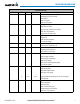
TABLE OF CONTENTS 1.1 1.2 1.3 1.4 1.5 1.6 1.7 1.8 SECTION 1 SYSTEM OVERVIEW System Description.................................................. 1 Line Replaceable Units (LRU).................................. 2 G1000 Controls......................................................... 7 PFD/MFD Controls......................................................... 7 Audio Panel Controls................................................... 10 Secure Digital (SD) Cards.....................................
TABLE OF CONTENTS 4.6 Audio Panel Preflight Procedure........................ 130 4.7 Abnormal Operation............................................ 131 Stuck Microphone...................................................... 131 COM Tuning Failure.................................................... 131 Audio Panel Fail-safe Operation.................................. 131 Reversionary Mode.................................................... 131 SECTION 5 FLIGHT MANAGEMENT 5.1 Introduction...................
TABLE OF CONTENTS 6.9 Traffic Information Service (TIS)......................... 394 Displaying TRAFFIC Data............................................ 395 Traffic Map Page........................................................ 397 TIS Alerts.................................................................. 398 System Status............................................................ 399 6.10 Garmin GTS 800 Traffic........................................ 402 Theory of operation..........................
TABLE OF CONTENTS 8.9 Flight Data Logging............................................. 550 8.10 Auxiliary Video (Optional)................................... 552 Video Setup.............................................................. 553 Display Selection....................................................... 553 Input Selection.......................................................... 554 Zoom/Range............................................................. 554 8.11 Abnormal Operation...............
SYSTEM OVERVIEW SYSTEM OVERVIEW SECTION 1 SYSTEM OVERVIEW FLIGHT INSTRUMENTS 1.1 SYSTEM DESCRIPTION This section is designed to provide an overview of the G1000 Integrated Flight Deck as installed in Cessna Nav III aircraft, which include the Cessna 172R, 172S, the normally aspirated Cessna 182 (182), the turbocharged Cessna 182 (T182), the normally aspirated Cessna 206 (206), and the turbocharged Cessna 206 (T206).
SYSTEM OVERVIEW SYSTEM OVERVIEW 1.2 LINE REPLACEABLE UNITS (LRU) AUDIO PANEL & CNS EIS FLIGHT INSTRUMENTS • GDU 1040/1044B – The GDU 1044B features a 10.4-inch LCD display with 1024 x 768 resolution. The left display is configured as a PFD and the right display is configured as an MFD. Both GDU 1044Bs link and display all functions of the G1000 system during flight. The displays communicate with each other through a High-Speed Data Bus (HSDB) Ethernet connection.
SYSTEM OVERVIEW SYSTEM OVERVIEW • GEA 71 (1) – Receives and processes signals from the engine and airframe sensors. This unit communicates with both GIA 63/63Ws using an RS-485 digital interface. FLIGHT INSTRUMENTS EIS • GRS 77 (1) – Provides aircraft attitude and heading information via ARINC 429 to both the GDU 1040/1044B and the GIA 63/63W.
SYSTEM OVERVIEW SYSTEM OVERVIEW FLIGHT INSTRUMENTS • GDL 69A (1) – A satellite radio receiver that provides real-time weather information to the G1000 MFD (and, indirectly, to the inset map of the PFD) as well as digital audio entertainment. The GDL 69A communicates with the MFD via HSDB connection. A subscription to the SiriusXM Satellite Radio service is required to enable the GDL 69A capability.
SYSTEM OVERVIEW SYSTEM OVERVIEW PFD GDU 1040 or GDU 1044B* MFD GDU 1040 or GDU 1044B* GMA 1347 Audio Panel FLIGHT INSTRUMENTS Reversionary Control Reversionary Control EIS GDC 74A Air Data Computer No.
EIS FLIGHT INSTRUMENTS SYSTEM OVERVIEW SYSTEM OVERVIEW AUDIO PANEL & CNS No. 1 GIA 63/63W Integrated Avionics Unit No.
SYSTEM OVERVIEW SYSTEM OVERVIEW 1.3 G1000 CONTROLS FLIGHT INSTRUMENTS NOTE: The Audio Panel (GMA 1347) and AFCS controls are described in the CNS & Audio Panel and AFCS sections respectively. The G1000 system controls are located on the PFD and MFD bezels and audio panel. The controls for the PFD and MFD are discussed within the following pages of this section.
SYSTEM OVERVIEW SYSTEM OVERVIEW PFD and MFD control functions are the same. – Controls the NAV audio level. Press to toggle the Morse code identifier ON and OFF. Volume level is shown in the field as a percentage. 1 NAV VOL/ID Knob FLIGHT INSTRUMENTS 2 NAV Frequency Transfer Key – Transfers the standby and active NAV frequencies. 3 Dual NAV Knob – Tunes the MHz (large knob) and kHz (small knob) standby frequencies for the NAV receiver.
SYSTEM OVERVIEW SYSTEM OVERVIEW FLIGHT INSTRUMENTS Data is Inserted Above the Cursor, Indicated by the Data Insertion Pointer Figure 1-4 Data Insertion Pointer EIS 15 AUDIO PANEL & CNS PROC Key – Selects approaches, departures and arrivals from the flight plan. If a flight plan is used, available procedures for the departure and/or arrival airport are automatically suggested. If a flight plan is not used, the desired airport and the desired procedure may be selected.
SYSTEM OVERVIEW SYSTEM OVERVIEW AUDIO PANEL & CNS EIS FLIGHT INSTRUMENTS AUDIO PANEL CONTROLS 1 2 3 4 5 6 7 8 9 10 11 12 13 14 15 16 HAZARD AVOIDANCE FLIGHT MANAGEMENT 17 18 19 20 21 22 23 24 AFCS Figure 1-5 Audio Panel Controls (GMA 1347) INDEX APPENDICES ADDITIONAL FEATURES NOTE: When a key is selected, a triangular annunciator above the key is illuminated. 10 1 COM1 MIC – Selects the #1 transmitter for transmitting.
SYSTEM OVERVIEW SPKR – Selects and deselects the cabin speaker. COM and NAV receiver audio can be heard on the speaker. 11 MKR/MUTE – Mutes the currently received marker beacon receiver audio. Unmutes when new marker beacon audio is received. Also, stops play of the clearance recorder. 12 HI SENS – Press to increase marker beacon receiver sensitivity. Press again to return to normal. 13 DME – Pressing turns DME audio on or off.
SYSTEM OVERVIEW SYSTEM OVERVIEW 1.4 SECURE DIGITAL (SD) CARDS FLIGHT INSTRUMENTS NOTE: Ensure the G1000 System is powered off before inserting an SD card. NOTE: Refer to Appendix B for instructions on loading database updates. AUDIO PANEL & CNS EIS The PFD and MFD data card slots use Secure Digital (SD) cards and are located on the upper right side of the display bezels. SD cards are used for storing the various databases and system software updates.
SYSTEM OVERVIEW SYSTEM OVERVIEW 1.5 SYSTEM POWER-UP FLIGHT INSTRUMENTS NOTE: See the Aircraft Flight Manual (AFM) for specific procedures concerning avionics power application and emergency power supply operation. NOTE: Refer to Appendix A for system-specific annunciations and alerts. EIS The G1000 System is integrated with the aircraft electrical system and receives power directly from electrical busses.
SYSTEM OVERVIEW SYSTEM OVERVIEW 1.6 SYSTEM OPERATION NOTE: In normal operating mode, backlighting can only be adjusted from the PFD. In reversionary mode, it FLIGHT INSTRUMENTS can be adjusted from the remaining display. The displays are connected together via a single Ethernet bus for high-speed communication. Each IAU is connected to a single display, as shown in Figure 1-1. This allows the units to share information, enabling true system integration..
SYSTEM OVERVIEW SYSTEM OVERVIEW FLIGHT INSTRUMENTS If a display fails, the appropriate IAU Ethernet interface to the display is cut off. Thus, the IAU can no longer communicate with the remaining display (refer to Figure 1-1), and the NAV and COM functions provided to the failed display by the IAU are flagged as invalid on the remaining display. The system reverts to backup paths for the AHRS, ADC, Engine/Airframe Unit, and Transponder, as required.
available unavailable GPS Data available unavailable EIS AUDIO PANEL & CNS FLIGHT MANAGEMENT AHRS no-GPS Mode le ab ail av AHRS no- AHRS no-Mag/ Mag Mode no-Air Mode Heading Invalid Air Data un available Air Data AHRS Normal Operation Magnetometer Data available unavailable available FLIGHT INSTRUMENTS Magnetometer Data unavailable SYSTEM OVERVIEW SYSTEM OVERVIEW Attitude/Heading Invalid Figure 1-12 AHRS Operation HAZARD AVOIDANCE GPS INPUT FAILURE NOTE: In-flight initialization of
SYSTEM OVERVIEW SYSTEM OVERVIEW G1000 SYSTEM ANNUNCIATIONS NOTE: For a detailed description of all annunciations and alerts, refer to Appendix A. Refer to the Pilot’s FLIGHT INSTRUMENTS Operating Handbook (POH) for additional information regarding pilot responses to these annunciations. When an LRU or an LRU function fails, a large red “X” is typically displayed on windows associated with the failed data (Figure 1-13 displays all possible flags and responsible LRUs).
SYSTEM OVERVIEW PFD SOFTKEYS FLIGHT INSTRUMENTS SYSTEM OVERVIEW The PFD softkeys provide control over flight management functions, including GPS, NAV, terrain, traffic, and lightning (optional). Each softkey sublevel has a BACK Softkey which can be selected to return to the previous level. The ALERTS Softkey is visible at all softkey levels (label changes if messages are issued).
SYSTEM OVERVIEW Wind direction arrows with headwind and crosswind components OPTN 2 Wind direction arrow and speed OPTN 3 Wind direction arrow with direction and speed OFF Information not displayed BRG1 Cycles the Bearing 1 Information Window through NAV1, GPS/ waypoint identifier and GPS-derived distance information, and ADF/frequency HSI FRMT Provides access to the HSI formatting softkeys 360 HSI Displays the HSI in a 360 degree view ARC HSI Displays the HSI as an arc ALT UNIT METERS Displ
EIS FLIGHT INSTRUMENTS SYSTEM OVERVIEW SYSTEM OVERVIEW Figure 1-15 Top Level PFD Softkeys (optional) ALERTS (optional) (optional) WX LGND STRMSCP FLIGHT MANAGEMENT AUDIO PANEL & CNS DME (optional) (optional) PRECIP or DL LTNG or TRFC-1 (optional) METAR ALERTS Press the BACK or OFF Softkey to return to the top-level softkeys.
SYSTEM OVERVIEW SYSTEM OVERVIEW DME ALERTS FLIGHT INSTRUMENTS ALERTS Press the BACK Softkey to return to the top-level softkeys. ALERTS EIS Press the BACK Softkey to return to the previous softkey level. Figure 1-18 XPDR (Transponder) Softkeys AUDIO PANEL & CNS MFD SOFTKEYS ENGINE LEAN CYL SLCT BACK SYSTEM GAL REM -1 GAL +10 GAL XX GAL 190-00498-07 Rev.
SYSTEM OVERVIEW SYSTEM OVERVIEW Enables second-level Navigation Map softkeys FLIGHT INSTRUMENTS MAP TRAFFIC Displays traffic information on Navigation Map PROFILE Displays/removes Profile View on Navigation Map Page Displays topographical data (e.g.
SYSTEM OVERVIEW CHECK EXIT Pressing this softkey checks off a checklist item. If an item is already checked, an UNCHECK Softkey is displayed. Press to exit the checklist EMERGCY Displays the emergency checklist FLIGHT INSTRUMENTS Displays the engine checklist SYSTEM OVERVIEW ENGINE EIS AUDIO PANEL & CNS FLIGHT MANAGEMENT HAZARD AVOIDANCE AFCS ADDITIONAL FEATURES APPENDICES INDEX 190-00498-07 Rev.
SYSTEM OVERVIEW SYSTEM OVERVIEW (All except Diesel) ENGINE DCLTR MAP SHW CHRT CHKLIST (optional) (optional) FLIGHT INSTRUMENTS DCLTR-1 DCLTR-2 DCLTR-3 (Default softkey is dependant on the selection made in the map setup options) (optional) PROFILE TOPO TERRAIN EIS TRAFFIC (optional) (optional) PRECIP or DL LTNG or AIRWAYS STRMSCP NEXRAD XM LTNG (optional) (optional) METAR LEGEND Press the BACK softkey to return to the top-level softkeys.
SYSTEM OVERVIEW SYSTEM OVERVIEW GPS RECEIVER OPERATION Each GIA 63/63W Integrated Avionics Unit (IAU) contains a GPS receiver. Information collected by the specified receiver (GPS1 for the #1 IAU or GPS2 for the #2 IAU) may be viewed on the AUX - GPS Status Page.
SYSTEM OVERVIEW SYSTEM OVERVIEW Satellite Signal Information Status GPS Receiver Status RAIM Availability Prediction FLIGHT INSTRUMENTS Satellite Constellation Diagram AUDIO PANEL & CNS EIS Enabled SBAS Options FLIGHT MANAGEMENT Satellite Signal Strength Bars RAIM Softkey Selected HAZARD AVOIDANCE Figure 1-20 GPS Status Page (RAIM or SBAS Selected) SBAS Softkey Selected The GPS Status Page provides the following information: • Satellite constellation diagram AFCS Satellites currently in view
SYSTEM OVERVIEW SYSTEM OVERVIEW FLIGHT INSTRUMENTS The GPS solution type (ACQUIRING, 2D NAV, 2D DIFF NAV, 3D NAV, 3D DIFF NAV) for the active GPS receiver (GPS1 or GPS2) is shown in the upper right of the GPS Status Page. When the receiver is in the process of acquiring enough satellite signals for navigation, the receiver uses satellite orbital data (collected continuously from the satellites) and last known position to determine the satellites that should be in view.
SYSTEM OVERVIEW SYSTEM OVERVIEW Or: a) To use the present position, press the MENU Key. FLIGHT INSTRUMENTS b) With ‘Set WPT to Present Position’ highlighted, press the ENT Key. c) Press the ENT Key to accept the waypoint entry. 6) Use the FMS Knob to enter an arrival time and press the ENT Key. 7) Use the FMS Knob to enter an arrival date and press the ENT Key. AUDIO PANEL & CNS EIS 8) With the cursor highlighting ‘COMPUTE RAIM?’, press the ENT Key.
SYSTEM OVERVIEW SYSTEM OVERVIEW 1.7 ACCESSING G1000 FUNCTIONALITY MENUS FLIGHT INSTRUMENTS EIS The G1000 has a MENU Key that, when pressed, displays a context-sensitive list of options. This options list allows the user to access additional features or make settings changes which specifically relate to the currently displayed window/page. There is no all-encompassing menu. Some menus provide access to additional submenus that are used to view, edit, select, and review options.
SYSTEM OVERVIEW SYSTEM OVERVIEW MFD PAGE GROUPS NOTE: Refer to the Flight Management, Hazard Avoidance, and Additional Features sections for details on FLIGHT INSTRUMENTS specific pages. EIS Information on the MFD is presented on pages which are grouped according to function. The page group and active page title are displayed in the upper center of the screen, below the Navigation Status Box.
SYSTEM OVERVIEW SYSTEM OVERVIEW Map Pages (MAP) Navigation Map FLIGHT INSTRUMENTS Traffic Map Stormscope® Weather Data Link (service optional) - XM WX Satellite Weather EIS - FIS-B Weather - GFDS Worldwide Weather AUDIO PANEL & CNS Terrain Proximity/Terrain-SVS/ TAWS-B Figure 1-23 Map Pages FLIGHT MANAGEMENT Waypoint Pages (WPT) Airport Information pages - Airport Information (INFO-1 Softkey) HAZARD AVOIDANCE - Airport Directory (INFO-2 Softkey) - Departure Information (DP Softkey) AFCS -
SYSTEM OVERVIEW SYSTEM OVERVIEW FLIGHT INSTRUMENTS Auxiliary Pages (AUX) Trip Planning Utility GPS Status System Setup EIS SiriusXM Satellite pages - XM Information (INFO Softkey) SiriusXM Satellite Pages AUDIO PANEL & CNS - XM Radio (RADIO Softkey) System Status FLIGHT MANAGEMENT Video (Optional) Figure 1-25 Auxiliary Pages Flight Plan Pages (FPL) HAZARD AVOIDANCE Active Flight Plan - Wide View, Narrow View (VIEW Softkey) Flight Plan Catalog AFCS or ADDITIONAL FEATURES Stored Flight Pla
SYSTEM OVERVIEW SYSTEM OVERVIEW Nearest Pages (NRST) Nearest Airports FLIGHT INSTRUMENTS Nearest Intersections Nearest NDB Nearest VOR Nearest User Waypoints EIS Nearest Frequencies Nearest Airspaces AUDIO PANEL & CNS Figure 1-27 Nearest Pages FLIGHT MANAGEMENT In addition to the main page groups accessed exclusively using the FMS Knobs, there are pages for flight planning (FPL) and loading procedures (PROC) which are accessed by bezel key.
SYSTEM OVERVIEW SYSTEM OVERVIEW MFD SYSTEM PAGES FLIGHT INSTRUMENTS In the Auxiliary (AUX) Page Group, there are two system pages: System Setup and System Status. The System Setup Page allows management of various system parameters, while the System Status Page displays the status of all G1000 system LRUs.
SYSTEM OVERVIEW SYSTEM OVERVIEW Date/Time FLIGHT INSTRUMENTS The Date/Time Box on the System Setup Page displays the current date and time and allows the pilot to set the time format (local 12-hr, local 24-hr, or UTC) and offset. The time offset is used to define current local time. UTC (also called GMT or Zulu) date and time are calculated directly from the GPS satellites signals and cannot be changed.
SYSTEM OVERVIEW SYSTEM OVERVIEW • Fuel and fuel flow (gallons, gallons/hour) Indicates fuel quantities are measured in gallons and fuel flow is measured in gallons per hour. FLIGHT INSTRUMENTS • Weight (pounds, kilograms) The weight setting is not applicable to the Nav III. • Position (HDDD°MM.MM’, HDDD°MM’SS.S”, MGRS) Affects all position displays. EIS Change a Display Units setting: 1) While on the System Setup Page, press the FMS Knob momentarily to activate the flashing cursor.
SYSTEM OVERVIEW SYSTEM OVERVIEW To turn an airspace alert on or off: 1) While on the System Setup Page, press the FMS Knob momentarily to activate the flashing cursor. 2) Turn the large FMS Knob to highlight the desired field in the Airspace Alerts Box. FLIGHT INSTRUMENTS 3) Turn the small FMS Knob clockwise to turn the airspace alert ON or counterclockwise to turn the alert OFF.
SYSTEM OVERVIEW SYSTEM OVERVIEW Page Navigation FLIGHT INSTRUMENTS The large FMS Knob displays the Page Group Tabs and navigates through the tabs. The small FMS Knob navigates through the pages listed within a specific group. The number of clicks it takes to display the Page Group Tabs and change to the next tab can be controlled from the Page Navigation box on the AUX - System Setup Page. OFF – Displays the Page Group Tabs with one click of either FMS Knob.
SYSTEM OVERVIEW SYSTEM OVERVIEW GPS CDI FLIGHT INSTRUMENTS The GPS CDI Box on the System Setup Page allows the pilot to define the range for the on-screen course deviation indicator (CDI). The range values represent full range deflection for the CDI to either side. The default setting is ‘AUTO’. At this setting, leaving the departure airport the CDI range is set to 1.0 nm and gradually ramps up to 2 nm beyond 30 nm from the departure airport. The CDI range is set to 2.
SYSTEM OVERVIEW SYSTEM OVERVIEW are not of appropriate surface from being displayed. Default settings are zero feet (or meters) for runway length and “HARD/SOFT” for runway surface type. FLIGHT INSTRUMENTS Select nearest airport surface matching criteria (any, hard only, hard/soft, water): 1) While on the System Setup Page, press the FMS Knob momentarily to activate the flashing cursor. 2) Turn the large FMS Knob to highlight the runway surface field in the Nearest Airports Box.
SYSTEM OVERVIEW SYSTEM OVERVIEW Pressing the Display Database Selection Softkey (background changes to grey indicting the softkey is selected) places the cursor in the DATABASE window. Use the FMS Knob to scroll through database information for the database information. Each press of the Display Database Selection Softkey will change the softkey label (PFD1 DB, etc) to indicate the display for which database information is displayed.
SYSTEM OVERVIEW SYSTEM OVERVIEW 3) Turn the small FMS Knob to select the timer counting direction (UP/DN) and press the ENT Key. 4) If a desired starting time is desired: FLIGHT INSTRUMENTS a) Use the large FMS Knob to highlight the HH:MM:SS field. b) Use the FMS Knob to enter the desired time and press the ENT Key. 5) Turn the large FMS Knob to highlight ‘START?’ and press the ENT Key to start the timer. The field changes to ‘STOP?’. 6) To stop the timer, press the ENT Key with ‘STOP?’ highlighted.
SYSTEM OVERVIEW SYSTEM OVERVIEW Trip Statistics FLIGHT INSTRUMENTS The odometer and trip odometer record the total mileage traveled from the last reset; these odometers can be reset independently. Resetting the trip odometer also resets the average trip groundspeed. Maximum groundspeed for the period of time since the last reset is also displayed. Resetting trip statistics readouts: 1) Use the FMS Knob to select the AUX - Utility Page. 2) Press the MENU Key.
SYSTEM OVERVIEW SYSTEM OVERVIEW 1.8 DISPLAY BACKLIGHTING The G1000 display and control backlighting can be adjusted either automatically or manually. FLIGHT INSTRUMENTS AUTOMATIC ADJUSTMENT EIS The existing instrument panel dimmer bus normally controls the PFD and MFD backlighting as well as the PFD and MFD bezels, MFD Control Unit, AFCS Control Unit and audio panel key annunciator lighting.
SYSTEM OVERVIEW SYSTEM OVERVIEW Adjust key backlighting manually: 1) Press the MENU Key on the PFD to display the PFD Setup Menu Window. ‘AUTO’ becomes highlighted to the right of ‘PFD DSPL’. FLIGHT INSTRUMENTS EIS Figure 1-33 Manual Key Lighting Adjustment AUDIO PANEL & CNS 2) Turn the large FMS Knob to highlight ‘PFD DSPL’. Turn the small FMS Knob in the direction of the green arrowhead to display ‘PFD KEY’.
INDEX APPENDICES ADDITIONAL FEATURES AFCS HAZARD AVOIDANCE FLIGHT MANAGEMENT AUDIO PANEL & CNS EIS FLIGHT INSTRUMENTS SYSTEM OVERVIEW SYSTEM OVERVIEW Blank Page 46 Garmin G1000 Pilot’s Guide for Cessna Nav III 190-00498-07 Rev.
FLIGHT INSTRUMENTS SYSTEM OVERVIEW SECTION 2 FLIGHT INSTRUMENTS FLIGHT INSTRUMENTS WARNING: If the airspeed, attitude, altitude, or heading indications become unusable, refer to the backup instruments. NOTE: The Automatic Flight Control System (AFCS) provides additional readouts and bugs on selected flight instruments. Refer to the AFCS Section for details on these bugs and readouts, as they appear on the display during certain AFCS modes.
SYSTEM OVERVIEW FLIGHT INSTRUMENTS FLIGHT INSTRUMENTS 20 19 18 17 1 16 15 2 EIS 14 AUDIO PANEL & CNS 13 3 12 FLIGHT MANAGEMENT 4 5 11 6 10 7 9 APPENDICES ADDITIONAL FEATURES AFCS HAZARD AVOIDANCE 8 1 NAV Frequency Box 11 Horizontal Situation Indicator (HSI) 2 Airspeed Indicator 12 Barometric Altimeter Setting 3 True Airspeed 13 Vertical Speed Indicator (VSI) 4 Current Heading 14 Reference Altitude Bug 5 Turn Rate Indicator 15 Altimeter 6 Heading Bug 16 Referenc
FLIGHT INSTRUMENTS SYSTEM OVERVIEW 15 16 14 FLIGHT INSTRUMENTS 1 2 13 EIS 12 11 3 AUDIO PANEL & CNS 10 4 9 5 FLIGHT MANAGEMENT 6 8 7 Flight Plan Window 2 Vspeed Reference 10 Annunciation Window 3 Selected Heading 11 Selected Course 4 Wind Data 12 Current Vertical Speed 5 Inset Map 13 Glideslope Indicator 6 DME Information Window 14 Marker Beacon Annunciation 7 Bearing Information Windows 15 Terrain Annunciation 8 Minimum Descent Altitude/Decision Height 16 AFCS Sta
SYSTEM OVERVIEW FLIGHT INSTRUMENTS 2.1 FLIGHT INSTRUMENTS FLIGHT INSTRUMENTS AIRSPEED INDICATOR NOTE: Refer to the Pilot’s Operating Handbook (POH) for airspeed criteria and Vspeed values. FLIGHT MANAGEMENT AUDIO PANEL & CNS EIS The Airspeed Indicator displays airspeed on a moving tape rolling number gauge. The true airspeed is displayed in knots below the Airspeed Indicator. The numeric labels and major tick marks on the moving tape are shown at intervals of 10 knots.
FLIGHT INSTRUMENTS SYSTEM OVERVIEW Vspeeds (Glide, VR, VX, and VY,) can be changed and their flags turned on/off from the Timer/References Window. When active (on), the Vspeeds are displayed to the right of the airspeed scale. Changing Vspeeds and turning Vspeed flags on/off: FLIGHT INSTRUMENTS 1) Press the TMR/REF Softkey. 2) Turn the large FMS Knob to highlight the field of the desired Vspeed to be changed. 3) Use the FMS Knob to enter the desired value.
SYSTEM OVERVIEW FLIGHT INSTRUMENTS ATTITUDE INDICATOR FLIGHT INSTRUMENTS Attitude information is displayed over a virtual blue sky and brown ground with a white horizon line. The Attitude Indicator displays the pitch, roll, and slip/skid information.
FLIGHT INSTRUMENTS SYSTEM OVERVIEW ALTIMETER FLIGHT INSTRUMENTS The Altimeter displays 600 feet of barometric altitude values at a time on a moving tape rolling number gauge. Numeric labels and major tick marks are shown at intervals of 100 feet. Minor tick marks are at intervals of 20 feet. The indicated altitude is displayed inside the black pointer. The Selected Altitude is displayed above the Altimeter in the box indicated by a selection bug symbol.
SYSTEM OVERVIEW FLIGHT INSTRUMENTS FLIGHT INSTRUMENTS The barometric pressure setting is displayed below the Altimeter in inches of mercury (in Hg) or hectopascals (hPa) when metric units are selected. Adjusting the altimeter barometric pressure setting creates discontinuities in VNV vertical navigation, moving the descent path. For large adjustments, it may take several minutes for the aircraft to re-establish on the descent patch.
FLIGHT INSTRUMENTS SYSTEM OVERVIEW FLIGHT INSTRUMENTS Pressure setting flashes during climb above transition altitude if the STD BARO Softkey has not been pressed. Pressure setting flashes during descent below transition altitude to indicate setting has not been changed from STD BARO.
SYSTEM OVERVIEW FLIGHT INSTRUMENTS VERTICAL DEVIATION NOTE: The Glidepath Indicator is only shown for aircraft with GIA 63W Integrated Avionics Units when FLIGHT INSTRUMENTS SBAS is available. EIS The Vertical Deviation Indicator (VDI) is a magenta chevron indicating the baro-VNV vertical deviation when Vertical Navigation (VNV) is being used. The VDI appears in conjunction with the “TOD within 1 minute” alert. The VDI is removed from the display if vertical deviation becomes invalid.
FLIGHT INSTRUMENTS SYSTEM OVERVIEW HORIZONTAL SITUATION INDICATOR (HSI) FLIGHT INSTRUMENTS The Horizontal Situation Indicator (HSI) displays a rotating compass card in a heading-up orientation. Letters indicate the cardinal points with numeric labels every 30˚. Major tick marks are at 10˚ intervals and minor tick marks are at 5˚ intervals. A digital reading of the current heading appears on top of the HSI, and the current track is represented on the HSI by a magenta diamond.
SYSTEM OVERVIEW FLIGHT INSTRUMENTS FLIGHT INSTRUMENTS The Arc HSI is a 140˚ expanded section of the compass rose. The Arc HSI contains a Course Pointer, combined To/From Indicator and a sliding deviation indicator, and a deviation scale. Upon station passage, the To/From Indicator flips and points to the tail of the aircraft, just like a conventional To/From flag.
FLIGHT INSTRUMENTS SYSTEM OVERVIEW Navigation angles (track, heading, course, bearing) are corrected to the computed magnetic variation (Mag Var) or referenced to true north (T), set on the AUX - System Setup Page. When an approach referenced to true north has been loaded into the flight plan, the system generates a message to change the navigation angle setting to True at the appropriate time.
SYSTEM OVERVIEW FLIGHT INSTRUMENTS TURN RATE INDICATOR FLIGHT INSTRUMENTS The Turn Rate Indicator is located directly above the rotating compass card. Tick marks to the left and right of the lubber line denote half-standard and standard turn rates. A magenta Turn Rate Trend Vector shows the current turn rate. The end of the trend vector gives the heading predicted in 6 seconds, based on the present turn rate.
FLIGHT INSTRUMENTS SYSTEM OVERVIEW When a bearing pointer is displayed, the associated information window is also displayed.
SYSTEM OVERVIEW FLIGHT INSTRUMENTS COURSE DEVIATION INDICATOR (CDI) NOTE: During a heading change of greater than 105˚ with respect to the course, the CDI on the Arc HSI FLIGHT INSTRUMENTS switches to the opposite side of the deviation scale and displays reverse sensing. The Course Deviation Indicator (CDI) moves left or right from the course pointer along a lateral deviation scale to display aircraft position relative to the course. If the course deviation data is not valid, the CDI is not displayed.
FLIGHT INSTRUMENTS SYSTEM OVERVIEW Changing navigation sources: 1) Press the CDI Softkey to change from GPS to VOR1 or LOC1. This places the light blue tuning box over the NAV1 standby frequency in the upper left corner of the PFD. FLIGHT INSTRUMENTS 2) Press the CDI Softkey again to change from VOR1 or LOC1 to VOR2 or LOC2. This places the light blue tuning box over the NAV2 standby frequency. 3) Press the CDI Softkey a third time to return to GPS.
SYSTEM OVERVIEW FLIGHT INSTRUMENTS GPS CDI SCALING FLIGHT INSTRUMENTS When GPS is the selected navigation source, the flight plan legs are sequenced automatically and annunciations appear on the HSI for the flight phase. Flight phase annunciations are normally shown in magenta, but when cautionary conditions exist the color changes to yellow. If the current leg in the flight plan is a heading leg, HDG LEG is annunciated in magenta beneath the aircraft symbol.
Enroute (Oceanic if >200 nm from nearest airport) Terminal Approach 0.3 nm 1.0 nm 1.0 nm 2.0 nm 0.3 nm 1.0 nm Terminal Refer to accompanying approach CDI scaling figures FLIGHT INSTRUMENTS Departure SYSTEM OVERVIEW CDI Full-scale Deflection FLIGHT INSTRUMENTS Missed Approach EIS AUDIO PANEL & CNS Figure 2-23 Automatic CDI Scaling • Once a departure procedure is activated, the CDI is scaled for departure (0.3 nm). • The system switches from departure to terminal CDI scaling (1.
2 nm FAF CDI scale varies if VTF is activated 0.3 nm 1.0 nm 2 nm FAF EIS angle based on database information course width angle set by system CDI Full-scale Deflection 0.3 nm 1.0 nm CDI scale is set to the smaller of 0.
FLIGHT INSTRUMENTS SYSTEM OVERVIEW OBS MODE NOTE: VNV is inhibited while automatic waypoint sequencing has been suspended. FLIGHT INSTRUMENTS Enabling Omni-bearing Selector (OBS) Mode suspends the automatic sequencing of waypoints in a GPS flight plan (GPS must be the selected navigation source), but retains the current Active-to waypoint as the navigation reference even after passing the waypoint. OBS is annunciated to the lower right of the aircraft symbol when OBS Mode is selected.
SYSTEM OVERVIEW FLIGHT INSTRUMENTS AUDIO PANEL & CNS EIS FLIGHT INSTRUMENTS As the aircraft crosses the missed approach point (MAP), automatic approach waypoint sequencing is suspended. SUSP appears on the HSI at the lower right of the aircraft symbol. The OBS Softkey label changes to indicate the suspension is active as shown in Figure 2-27. Pressing the SUSP Softkey, deactivates the suspension and resumes automatic sequencing of approach waypoints.
FLIGHT INSTRUMENTS SYSTEM OVERVIEW 2.2 SUPPLEMENTAL FLIGHT DATA FLIGHT INSTRUMENTS NOTE: Pressing the DFLTS Softkey turns off metric Altimeter display, the Inset Map and wind data display. In addition to the flight instruments, the PFD also displays various supplemental information, including temperatures, wind data, and Vertical Navigation (VNV) indications.
SYSTEM OVERVIEW FLIGHT INSTRUMENTS Changing temperature display units: 1) Select the AUX - System Setup Page on the MFD using the FMS Knob. FLIGHT INSTRUMENTS 2) Press the FMS Knob to activate the cursor. 3) Turn the large FMS Knob to highlight the TEMP field in the Display Units box. 4) Turn the small FMS Knob to highlight either CELSIUS or FAHRENHEIT and press the ENT Key to confirm the selection.
FLIGHT INSTRUMENTS SYSTEM OVERVIEW WIND DATA Option 2 Option 3 No Data EIS Option 1 FLIGHT INSTRUMENTS Wind direction and speed in knots can be displayed relative to the aircraft in a window to the upper left of the HSI. When the window is selected for display, but wind information is invalid or unavailable, the window displays NO WIND DATA. Wind data can be displayed in three different ways.
SYSTEM OVERVIEW FLIGHT INSTRUMENTS VERTICAL NAVIGATION (VNV) INDICATIONS FLIGHT INSTRUMENTS When a VNV flight plan has been activated, VNV indications (VNV Target Altitude, RVSI, VDI) appear on the PFD in conjunction with the “TOD within 1 minute” message and “Vertical track” voice alert. See the Flight Management and AFCS sections for details on VNV features. VNV indications are removed from the PFD according to the criteria listed in the Table 2-2.
FLIGHT INSTRUMENTS SYSTEM OVERVIEW 2.3 PFD ANNUNCIATIONS AND ALERTING FUNCTIONS FLIGHT INSTRUMENTS The following annunciations and alerting functions are displayed on the PFD. Refer to Appendix A for more information on alerts and annunciations. SYSTEM ALERTING EIS Messages appear in the Alerts Window in the lower right corner of the PFD when a warning, caution, advisory alert, or system message advisory occurs.
SYSTEM OVERVIEW FLIGHT INSTRUMENTS MARKER BEACON ANNUNCIATIONS FLIGHT INSTRUMENTS Marker Beacon Annunciations are displayed on the PFD to the left of the Selected Altitude. Outer marker reception is indicated in blue, middle in yellow, and inner in white. Refer to the Audio Panel and CNS Section for more information on Marker Beacon Annunciations.
FLIGHT INSTRUMENTS SYSTEM OVERVIEW TAWS ANNUNCIATIONS Terrain Awareness and Warning System (TAWS) annunciations appear on the PFD at the top left of the Altimeter. Refer to the Hazard Avoidance Section and Appendix A for information on TAWS alerts and annunciations. FLIGHT INSTRUMENTS EIS AUDIO PANEL & CNS FLIGHT MANAGEMENT HAZARD AVOIDANCE Figure 2-35 Traffic and TAWS Annunciations AFCS ADDITIONAL FEATURES APPENDICES INDEX 190-00498-07 Rev.
SYSTEM OVERVIEW FLIGHT INSTRUMENTS ALTITUDE ALERTING FLIGHT INSTRUMENTS Altitude Alerting provides the pilot with a visual alert when approaching the Selected Altitude. Whenever the Selected Altitude is changed, the Altitude Alerter is reset. Altitude alerting tones and visual alerts occur only if the GFC 700 is installed. The following occur when approaching the Selected Altitude: • Upon passing through 1000 feet of the Selected Altitude an aural tone is heard.
FLIGHT INSTRUMENTS SYSTEM OVERVIEW MINIMUM DESCENT ALTITUDE/DECISION HEIGHT ALERTING FLIGHT INSTRUMENTS For altitude awareness, a barometric Minimum Descent Altitude (MDA) or Decision Height (DH) can be set in the Timer/References Window and is reset when the power is cycled. When active, the altitude setting is displayed to the bottom left of the Altimeter. Once the altitude is within the range of the tape, a bug appears at the reference altitude on the Altimeter.
SYSTEM OVERVIEW FLIGHT INSTRUMENTS 2.4 ABNORMAL OPERATIONS FLIGHT INSTRUMENTS ABNORMAL GPS CONDITIONS The annunciations listed in Table 2-3 can appear on the HSI when abnormal GPS conditions occur. Refer to the Flight Management Section for more information on Dead Reckoning Mode.
FLIGHT INSTRUMENTS SYSTEM OVERVIEW UNUSUAL ATTITUDES Nose High FLIGHT INSTRUMENTS When the aircraft enters an unusual pitch attitude, red chevrons pointing toward the horizon warn of extreme pitch. The chevrons are displayed on the Attitude Indicator, starting at 50˚ above and 30˚ below the horizon line.
INDEX APPENDICES ADDITIONAL FEATURES AFCS HAZARD AVOIDANCE FLIGHT MANAGEMENT AUDIO PANEL & CNS EIS FLIGHT INSTRUMENTS SYSTEM OVERVIEW FLIGHT INSTRUMENTS Blank Page 80 Garmin G1000 Pilot’s Guide for Cessna Nav III 190-00498-07 Rev.
ENGINE INDICATION SYSTEM SYSTEM OVERVIEW SECTION 3 ENGINE INDICATION SYSTEM (EIS) NOTE: Refer to the Pilot’s Operating Handbook (POH) for limitations. FLIGHT INSTRUMENTS The Engine Indication System (EIS) displays critical engine, electrical, fuel, and other system parameters on the left side of the Multi Function Display (MFD) during normal operations (Figure 3-1).
SYSTEM OVERVIEW ENGINE INDICATION SYSTEM EIS information is presented in three displays, accessed using the ENGINE Softkey on the MFD.
ENGINE INDICATION SYSTEM SYSTEM OVERVIEW 3.1 ENGINE DISPLAY FLIGHT INSTRUMENTS The Engine Display is the default EIS display and can be displayed after viewing other EIS displays by pressing the ENGINE softkey. This display shows the dial gauge(s), horizontal bar indicators, and readouts for critical engine and electrical parameters. The EIS automatically defaults back to the Engine Display from the Lean or System Display when certain parameters are exceeded.
9 Vacuum Pressure Indicator Displays standby vacuum pump pressure (VAC) Models 172R and 172S 10 Fuel Quantity Indicator (FUEL QTY GAL) Displays the quantity of fuel in gallons (gal) in each tank (left–L and right–R) from zero to full (F) When full, the indicator displays to 35 gal per side (24 gal for Models 172R and 172S) 11 Engine Hours (Tach) (ENG HRS) Models 172R and 172S Displays a numeric readout for the time in hours (hrs) the engine has been in service 12 Voltmeter (M, E BUS VOLTS) Display
ENGINE INDICATION SYSTEM SYSTEM OVERVIEW 1 Cruise Manifold Pressure Model T206H FLIGHT INSTRUMENTS Model T182T 1 4 Maximum Takeoff Fuel Flow 3 AUDIO PANEL & CNS Cruise Fuel Flow 3 EIS 2 2 4 6 6 8 8 10 10 12 12 13 13 HAZARD AVOIDANCE 5 FLIGHT MANAGEMENT 5 AFCS Figure 3-5 Engine Display (Turbocharged Aircraft) ADDITIONAL FEATURES Ascending through 5300 ft or descending below 9700 ft APPENDICES Descending below 4700 ft Ascending through 10,300 ft Figure 3-6 172S Tachometer
SYSTEM OVERVIEW ENGINE INDICATION SYSTEM 3.2 LEAN DISPLAY FLIGHT INSTRUMENTS NOTE: The pilot should follow the engine manufacturer’s recommended leaning procedures in the Pilot’s Operating Handbook (POH). EIS The Lean Display is accessed by pressing the ENGINE Softkey followed by the LEAN Softkey and provides information for performing engine leaning. The engine gauge(s) and Fuel Quantity Indicator remain on the Lean Display and fuel flow is listed as a numeric readout.
ENGINE INDICATION SYSTEM Displays propeller speeds in revolutions per minute (rpm) Red range indicates propeller overspeed warning Models 172S, 206H, and T206H – White high-rpm range indicates above normal operating speeds Model 172S – When ascending through 5300 ft, the upper end of the green arc displays 2600 rpm and ascending through 10,300 displays 2700 rpm.
SYSTEM OVERVIEW ENGINE INDICATION SYSTEM NORMALLY-ASPIRATED AIRCRAFT FLIGHT INSTRUMENTS For normally-aspirated aircraft, when a cylinder peaks, its peak is represented by a light blue block on the EGT Bar Graph. The EGT readout for the peaked cylinder number, indicated on the bar graph in light blue, appears directly beneath the bar graph.
ENGINE INDICATION SYSTEM SYSTEM OVERVIEW TURBOCHARGED AIRCRAFT FLIGHT INSTRUMENTS Leaning for turbocharged aircraft is done with reference to the Turbine Inlet Temperature (TIT). When the temperature peaks, the numeric readout (DPEAK) appears below the TIT Indicator and displays the difference between peak and current TITs, in degrees Fahrenheit (°F). If a peak is not displayed, underscores are shown until one is established.
SYSTEM OVERVIEW ENGINE INDICATION SYSTEM 3.3 SYSTEM DISPLAY FLIGHT INSTRUMENTS NORMALLY-ASPIRATED AND TURBOCHARGED AIRCRAFT NOTE: Fuel calculations do not use the aircraft fuel quantity indicators and are calculated from the last time the fuel was reset. NOTE: Refer to the Pilot’s Operating Handbook (POH) for fuel values and limitations. The displayed fuel EIS remaining can be adjusted up to 53 gal (Models 172R, 172S) or 87 gal (Models 182T, T182T, 206H, T206H).
ENGINE INDICATION SYSTEM Displays the engine oil temperature in degrees Fahrenheit (°F) 5 Displays a numeric readout for the time in hours (hrs) the engine has Engine Hours (Tach) been in service (ENG HRS) Models 182T, T182T, 206H, T206H 6 Displays vacuum pump pressure for the standby instruments Vacuum Pressure Indicator (VAC) Models 182T, T182T, 206H, T206H 7 Fuel Flow (FFLOW GPH) Displays the current fuel flow in gallons per hour (gph) 8 Calculated Fuel Used (GAL USED) Displays quantity of fue
FLIGHT INSTRUMENTS SYSTEM OVERVIEW ENGINE INDICATION SYSTEM Model 172R 2 Model 206H 1 1 2 2 3 3 4 4 5 5 6 6 7 7 8 8 9 9 10 10 AUDIO PANEL & CNS 7 7 8 8 9 9 HAZARD AVOIDANCE 3 FLIGHT MANAGEMENT EIS 2 Model 182T Model 172S 3 4 4 AFCS 10 10 11 11 11 11 12 12 12 12 INDEX APPENDICES ADDITIONAL FEATURES Figure 3-9 System Display (Normally-Aspirated Aircraft) 92 Garmin G1000 Pilot’s Guide for Cessna Nav III 190-00498-07 Rev.
ENGINE INDICATION SYSTEM SYSTEM OVERVIEW 1 Cruise Manifold Pressure FLIGHT INSTRUMENTS Model T182T Model T206H 1 EIS 4 4 5 5 6 6 7 7 8 8 9 9 10 10 11 11 12 12 AFCS 3 HAZARD AVOIDANCE 3 FLIGHT MANAGEMENT 2 AUDIO PANEL & CNS 2 ADDITIONAL FEATURES Figure 3-10 System Display (Turbocharged Aircraft) APPENDICES INDEX 190-00498-07 Rev.
INDEX APPENDICES ADDITIONAL FEATURES AFCS HAZARD AVOIDANCE FLIGHT MANAGEMENT AUDIO PANEL & CNS EIS FLIGHT INSTRUMENTS SYSTEM OVERVIEW ENGINE INDICATION SYSTEM Blank Page 94 Garmin G1000 Pilot’s Guide for Cessna Nav III 190-00498-07 Rev.
AUDIO PANEL AND CNS SYSTEM OVERVIEW SECTION 4 AUDIO PANEL AND CNS FLIGHT INSTRUMENTS 4.1 OVERVIEW The Communication/Navigation/Surveillance (CNS) system includes the Audio Panel, communication radios, navigation radios, and Mode S transponder. The System Overview Section provides a block diagram description of the Audio Panel and CNS system interconnection.
SYSTEM OVERVIEW AUDIO PANEL AND CNS MFD/PFD CONTROLS AND FREQUENCY DISPLAY 2 3 4 5 6 7 8 FLIGHT MANAGEMENT AUDIO PANEL & CNS EIS FLIGHT INSTRUMENTS 1 9 10 HAZARD AVOIDANCE 11 12 INDEX APPENDICES ADDITIONAL FEATURES AFCS Figure 4-1 MFD/PFD Controls, COM/NAV Frequency Tuning Boxes, and DME Tuning Window (Cessna 172R PFD Shown) 96 Garmin G1000 Pilot’s Guide for Cessna Nav III 190-00498-07 Rev.
AUDIO PANEL AND CNS NAV Frequency Box – Displays NAV standby and active frequency fields, volume, and station ID. The frequency of the NAV radio selected for navigation is displayed in green. 5 COM Frequency Box – Displays COM standby and active frequency fields and volume. The selected COM transceiver frequency is displayed in green. 6 COM Knob – Tunes the standby frequencies for the COM transceiver (large knob for MHz; small knob for kHz).
SYSTEM OVERVIEW AUDIO PANEL AND CNS 3 4 5 6 7 8 9 10 11 12 14 15 16 AUDIO PANEL & CNS 2 13 FLIGHT MANAGEMENT 1 18 19 20 21 HAZARD AVOIDANCE EIS FLIGHT INSTRUMENTS AUDIO PANEL CONTROLS 22 23 17 24 AFCS Figure 4-2 Audio Panel Controls INDEX APPENDICES ADDITIONAL FEATURES NOTE: When a key is selected, a triangular annunciator above the key is illuminated. 98 1 COM1 MIC – Selects the #1 transmitter for transmitting.
AUDIO PANEL AND CNS SPKR – Selects and deselects the cabin speaker. COM and NAV receiver audio can be heard on the speaker. 11 MKR/MUTE – Selects marker beacon receiver audio. Mutes the currently received marker beacon receiver audio. Unmutes automatically when new marker beacon audio is received. Also, stops play of recorded COM audio. 12 HI SENS – Press to increase marker beacon receiver sensitivity. Press again to return to low sensitivity. 13 DME – Turns optional DME audio on or off.
SYSTEM OVERVIEW AUDIO PANEL AND CNS 4.2 COM OPERATION FLIGHT INSTRUMENTS COM TRANSCEIVER SELECTION AND ACTIVATION NOTE: During PA Mode, the COM MIC Annunciator is extinguished and the COM active frequency color changes to white, indicating that neither COM transmitter is active. NOTE: When turning on the G1000 for use, the system remembers the last frequencies used and the active EIS COM transceiver state prior to shutdown.
AUDIO PANEL AND CNS SYSTEM OVERVIEW TRANSMIT/RECEIVE INDICATIONS FLIGHT INSTRUMENTS During COM transmission, a white TX appears by the active COM frequency replacing the Frequency Transfer Arrow. On the Audio Panel, when the active COM is transmitting, the active transceiver COM MIC Key Annunciator flashes approximately once per second. During COM signal reception, a white RX appears by the active COM frequency replacing the Frequency Transfer Arrow.
SYSTEM OVERVIEW AUDIO PANEL AND CNS SELECTING THE RADIO TO BE TUNED FLIGHT INSTRUMENTS Press the small COM Knob to transfer the frequency tuning box and Frequency Transfer Arrow between the upper and lower radio frequency fields. EIS Press the COM Knob to Switch the Tuning Box From One COM Radio to the Other AUDIO PANEL & CNS Figure 4-6 Switching COM Tuning Boxes QUICK-TUNING AND ACTIVATING 121.
AUDIO PANEL AND CNS SYSTEM OVERVIEW AUTO-TUNING THE COM FREQUENCY COM frequencies can be automatically tuned from the following: • Nearest Airports Window (PFD) • NRST – Nearest Frequencies Page (ARTCC, FSS, WX) FLIGHT INSTRUMENTS • WPT – Airport Information Page • NRST – Nearest Airspaces Page • NRST – Nearest Airports Page AUTO-TUNING FROM THE PFD EIS COM frequencies for the nearest airports can be automatically tuned from the Nearest Airports Window on the PFD.
SYSTEM OVERVIEW AUDIO PANEL AND CNS AUTO-TUNING FROM THE MFD FLIGHT INSTRUMENTS Frequencies can be automatically loaded into the COM Frequency Box from pages in the NRST or WPT page group by highlighting the frequency and pressing the ENT Key (Figures 4-9, 4-10, and 4-11). Auto-tuning a COM frequency from the WPT and NRST Pages: 1) From any page that the COM frequency can be auto-tuned, activate the cursor by pressing the FMS Knob or the appropriate softkey.
AUDIO PANEL AND CNS SYSTEM OVERVIEW On the WPT - Airport Information Page, the cursor can be placed on the frequency field by pressing the FMS Knob and scrolling through the list. The frequency is transferred to the COM Standby Field with the ENT Key.
SYSTEM OVERVIEW AUDIO PANEL AND CNS ADDITIONAL FEATURES AFCS HAZARD AVOIDANCE FLIGHT MANAGEMENT AUDIO PANEL & CNS EIS FLIGHT INSTRUMENTS COM frequencies can also be auto-tuned from the NRST – Nearest Airspaces, NRST – Nearest Frequencies, and NRST – Nearest Airports Pages on the MFD in a similar manner using the appropriate softkeys or MENU Key, the FMS Knob, and the ENT Key.
AUDIO PANEL AND CNS SYSTEM OVERVIEW FREQUENCY SPACING FLIGHT INSTRUMENTS The G1000 COM radios can tune either 25-kHz spacing (118.000 to 136.975 MHz) or 8.33-kHz spacing (118.000 to 136.990 MHz) for 760-channel or 3040-channel configuration. When 8.33-kHz channel spacing is selected, all of the 25-kHz channel spacing frequencies are also available in the complete 3040-channel list. COM channel spacing is set on the System Setup Page of the AUX Page Group. 25-kHz Channel Spacing EIS 8.
SYSTEM OVERVIEW AUDIO PANEL AND CNS AUTOMATIC SQUELCH FLIGHT INSTRUMENTS Automatic Squelch quiets unwanted static noise when no audio signal is received, while still providing good sensitivity to weak COM signals. To disable Automatic Squelch, press the VOL/SQ Knob. When Automatic Squelch is disabled, COM audio reception is always on. Continuous static noise is heard over the headsets and speaker, if selected. Pressing the VOL/SQ Knob again enables Automatic Squelch.
AUDIO PANEL AND CNS SYSTEM OVERVIEW 4.3 NAV OPERATION NAV RADIO SELECTION AND ACTIVATION FLIGHT INSTRUMENTS The NAV Frequency Box is composed of four fields; two standby fields and two active fields. The active frequencies are on the right side and the standby frequencies are on the left. EIS A NAV radio is selected for navigation by pressing the CDI Softkey located on the PFD. The active NAV frequency selected for navigation is displayed in green.
SYSTEM OVERVIEW AUDIO PANEL AND CNS EIS FLIGHT INSTRUMENTS NAV radios are selected for listening by pressing the corresponding keys on the Audio Panel. Pressing the NAV1, NAV2, ADF, or DME Key selects and deselects the navigation radio source. Selected audio can be heard over the headset and the speaker (if selected). All radios can be selected individually or simultaneously.
AUDIO PANEL AND CNS SYSTEM OVERVIEW SELECTING THE RADIO TO BE TUNED Press the small NAV Knob to transfer the frequency tuning box and Frequency Transfer Arrow between the upper and lower radio frequency fields. FLIGHT INSTRUMENTS Press the NAV Knob to Switch the Tuning Box From One NAV Radio to the Other EIS Figure 4-20 Switching NAV Tuning Boxes AUDIO PANEL & CNS VOR/LOC ID When the Morse code Identifier audio is on for a NAV radio, a white ID appears to the left of the active NAV frequency.
SYSTEM OVERVIEW AUTO-TUNING A NAV FREQUENCY FROM THE MFD FLIGHT INSTRUMENTS AUDIO PANEL AND CNS • WPT – VOR Information • NRST – Nearest Frequencies (FSS, WX) • NRST – Nearest Airports • NRST – Nearest Airspaces NAV frequencies can be selected and loaded from the following MFD pages: • WPT – Airport Information • NRST – Nearest VOR EIS The MFD provides auto-tuning of NAV frequencies from waypoint and nearest pages.
AUDIO PANEL AND CNS SYSTEM OVERVIEW Or: 1) When on the NRST pages, press the MENU Key to display the page menu. 2) Turn the large FMS Knob to scroll through the menu options. FLIGHT INSTRUMENTS 3) Press the ENT Key to place the cursor in the desired window. 4) Scroll through the frequency selections with the FMS Knob. 5) Press the ENT Key to load the NAV frequency into the standby field of the selected NAV radio.
SYSTEM OVERVIEW AUDIO PANEL AND CNS FLIGHT MANAGEMENT AUDIO PANEL & CNS EIS FLIGHT INSTRUMENTS In the example shown, the VOR list is selected with the VOR Softkey or from the page menu. The FMS Knob or ENT Key is used to scroll through the list. The cursor is placed on the frequency with the FREQ Softkey and loaded into the NAV Tuning Box with the ENT Key. Press the ENT Key to Load the Frequency into the NAV Standby Field.
AUDIO PANEL AND CNS SYSTEM OVERVIEW While enroute, NAV frequencies can also be auto-tuned from the NRST – Nearest Airports, WPT – Airport Information, WPT – VOR Information, and NRST – Nearest Frequencies Pages on the MFD in a similar manner using the appropriate softkeys or MENU Key, the FMS Knob, and the ENT Key.
SYSTEM OVERVIEW AUDIO PANEL AND CNS AUTO-TUNING NAV FREQUENCIES ON APPROACH ACTIVATION FLIGHT INSTRUMENTS NOTE: The primary NAV frequency is auto-tuned upon loading a VOR or ILS/Localizer approach. NOTE: When an ILS/LOC approach has been activated while navigating by GPS, the system automatically switches to LOC as the final approach course is intercepted (within 15 nm of the FAF). See the Flight Management Section for details.
AUDIO PANEL AND CNS SYSTEM OVERVIEW MARKER BEACON RECEIVER NOTE: The marker beacon indicators operate independently of marker beacon audio and cannot be turned FLIGHT INSTRUMENTS off. The marker beacon receiver is used as part of the ILS. The marker beacon receiver is always on and detects any marker beacon signals within the reception range of the aircraft.
SYSTEM OVERVIEW AUDIO PANEL AND CNS DME TUNING FLIGHT INSTRUMENTS NOTE: When another auxiliary window is turned on, the DME Tuning Window is replaced on the PFD. NOTE: When turning on the G1000 for use, the system remembers the last frequency used for DME tuning and the NAV1, NAV2, or HOLD state prior to shutdown. The G1000 System tunes the optional DME transceiver. The UHF DME frequency is tuned by pairing with a VHF NAV frequency.
AUDIO PANEL AND CNS SYSTEM OVERVIEW 4.4 GTX 33 MODE S TRANSPONDER FLIGHT INSTRUMENTS The GTX 33 Mode S Transponder provides Mode A, Mode C, and Mode S interrogation and reply capabilities.
FLIGHT INSTRUMENTS SYSTEM OVERVIEW AUDIO PANEL AND CNS STBY ON ALT GND VFR XPDR IDENT CODE IDENT BACK ALERTS EIS Pressing the BACK Softkey returns to the top-level softkeys. 1 AUDIO PANEL & CNS 0 2 3 4 5 6 IDENT 7 BKSP BACK ALERTS Pressing the BACK Softkey returns to the mode selection softkeys.
AUDIO PANEL AND CNS SYSTEM OVERVIEW STANDBY MODE (MANUAL) NOTE: In Standby Mode, the IDENT function is inoperative. FLIGHT INSTRUMENTS Standby Mode can be selected at any time by pressing the STBY Softkey. In Standby, the transponder does not reply to interrogations, but new codes can be entered. When Standby is selected, a white STBY indication and transponder code appear in the mode field of the Transponder Data Box. In all other modes, these fields appear in green.
SYSTEM OVERVIEW ALTITUDE MODE (AUTOMATIC OR MANUAL) FLIGHT INSTRUMENTS AUDIO PANEL AND CNS If Altitude Mode is selected, a green ALT indication and transponder code appear in the mode field of the Transponder Data Box, and all transponder replies requesting altitude information are provided with pressure altitude information. Altitude Mode is automatically selected when the aircraft becomes airborne. Altitude Mode may also be selected manually by pressing the ALT Softkey.
AUDIO PANEL AND CNS SYSTEM OVERVIEW ENTERING A TRANSPONDER CODE Entering a transponder code with softkeys: FLIGHT INSTRUMENTS 1) Press the XPDR Softkey to display the Transponder Mode Selection Softkeys. 2) Press the CODE Softkey to display the Transponder Code Selection Softkeys, for digit entry. 3) Press the digit softkeys to enter the code in the code field.
SYSTEM OVERVIEW AUDIO PANEL AND CNS VFR CODE FLIGHT INSTRUMENTS The VFR code can be entered either manually or by pressing the XPDR Softkey, then the VFR Softkey. When the VFR Softkey is pressed, the pre-programmed VFR code is automatically displayed in the code field of the Transponder Data Box. Pressing the VFR Softkey again restores the previous identification code. The pre-programmed VFR Code is set at the factory to 1200.
AUDIO PANEL AND CNS SYSTEM OVERVIEW 4.5 ADDITIONAL AUDIO PANEL FUNCTIONS POWER-UP FLIGHT INSTRUMENTS The Audio Panel performs a self-test during power-up. During the self-test all Audio Panel annunciator lights illuminate for approximately two seconds. Once the self-test is completed, most of the settings are restored to those in use before the unit was last turned off. MONO/STEREO HEADSETS EIS Stereo headsets are recommended for use in this aircraft.
SYSTEM OVERVIEW AUDIO PANEL AND CNS INTERCOM FLIGHT INSTRUMENTS The Audio Panel includes a four-position intercom system (ICS) in the 172R/S, 172TD, and (T)182T 182, and a six-position ICS in the (T)206H plus a stereo music input for the pilot, copilot and up to two passengers. The intercom provides pilot and copilot isolation from the passengers and aircraft radios.
AUDIO PANEL AND CNS SYSTEM OVERVIEW INTERCOM VOLUME AND SQUELCH FLIGHT INSTRUMENTS The PILOT/PASS Knob controls volume or manual squelch adjustment for the pilot and copilot/passenger. The small knob controls the pilot volume and squelch. The large knob controls the copilot/passenger volume and squelch. The VOL and SQ annunciations at the bottom of the unit indicate which function the knob is controlling.
SYSTEM OVERVIEW AUDIO PANEL AND CNS PASSENGER ADDRESS (PA) SYSTEM EIS FLIGHT INSTRUMENTS A passenger address system is available for delivering voice messages over the cabin speaker in the (T)182T and (T)206H only. When the PA Key is selected on the Audio Panel, the COM MIC Annunciator is extinguished, and the active COM frequency changes to white, indicating that there is no COM selected. A Push-to-Talk (PTT) must be pressed to deliver PA announcements.
AUDIO PANEL AND CNS SYSTEM OVERVIEW ENTERTAINMENT INPUTS NOTE: Auxiliary entertainment inputs cannot be completely turned off. Audio level for the AUX Audio In FLIGHT INSTRUMENTS input can be adjusted by a Garmin-authorized service center. NOTE: The AUX Audio In stereo entertainment input is not controlled by the AUX Key on the Audio Panel. The AUX Key is reserved for an auxiliary radio input.
SYSTEM OVERVIEW AUDIO PANEL AND CNS 4.6 AUDIO PANEL PREFLIGHT PROCEDURE FLIGHT INSTRUMENTS NOTE: If the pilot and/or copilot are using headsets that have a high/low switch or volume control knob, verify that the switch is in the high position and the volume control on the headsets are at maximum volume setting. On single‑pilot flights, verify that all other headsets are not connected to avoid excess noise in the audio system.
AUDIO PANEL AND CNS SYSTEM OVERVIEW 4.7 ABNORMAL OPERATION FLIGHT INSTRUMENTS Abnormal operation of the G1000 includes equipment failures of the G1000 components and failure of associated equipment, including switches and external devices. STUCK MICROPHONE If the push-to-talk (PTT) Key becomes stuck, the COM transmitter stops transmitting after 35 seconds of continuous operation. An alert appears on the PFD to advise the pilot of a stuck microphone.
INDEX APPENDICES ADDITIONAL FEATURES AFCS HAZARD AVOIDANCE FLIGHT MANAGEMENT AUDIO PANEL & CNS EIS FLIGHT INSTRUMENTS SYSTEM OVERVIEW AUDIO PANEL AND CNS Blank Page 132 Garmin G1000 Pilot’s Guide for Cessna Nav III 190-00498-07 Rev.
FLIGHT MANAGEMENT SYSTEM OVERVIEW SECTION 5 FLIGHT MANAGEMENT FLIGHT INSTRUMENTS 5.1 INTRODUCTION The G1000 is an integrated flight, engine, communication, navigation and surveillance system. This section of the Pilot’s Guide explains flight management using the G1000. EIS The most prominent part of the G1000 are the two full color displays: one Primary Flight Display (PFD) and one Multi Function Display (MFD).
SYSTEM OVERVIEW FLIGHT MANAGEMENT FLIGHT INSTRUMENTS Navigation Status Box Navigation Mode Inset Map AUDIO PANEL & CNS EIS Location of: - Direct To Window - Flight Plan Window - Procedures Window - Nearest Airports Window Figure 5-1 GPS Navigation Information on the PFD FLIGHT MANAGEMENT Navigation Status Box Map Orientation Navigation Page Title Navigation Map HAZARD AVOIDANCE - Aviation Data - Geographic Data - Topographic Data - Hazard Data Aircraft Icon at Present Position Active Flight P
FLIGHT MANAGEMENT • Distance (DIS) and Bearing (BRG) to the next waypoint or flight plan annunciations (e.g., ‘TOD within 1 minute’) • Bearing (BRG) The symbols used in the PFD status bar are: Symbol Description Active Leg FLIGHT INSTRUMENTS The Navigation Status Box located at the top of the MFD contains four data fields, each displaying one of the following items: SYSTEM OVERVIEW • Active flight plan leg (e.g., ‘D-> KICT’ or ‘KIXD -> KCOS’) or flight plan annunciations (e.g.
SYSTEM OVERVIEW FLIGHT MANAGEMENT 5.2 USING MAP DISPLAYS AUDIO PANEL & CNS EIS FLIGHT INSTRUMENTS Map displays are used extensively in the G1000 to provide situational awareness in flight. Most G1000 maps can display the following information: • Airports, NAVAIDs, airspaces, airways, land data • Aircraft icon (representing present position) (highways, cities, lakes, rivers, borders, etc.
FLIGHT MANAGEMENT SYSTEM OVERVIEW • Desired track up (DTK UP) aligns the top of the map display to the desired course. • Heading up (HDG UP) aligns the top of the map display to the current aircraft heading. FLIGHT INSTRUMENTS NOTE: When panning or reviewing active flight plan legs in a non-North Up orientation, the map does not show the map orientation nor the wind direction and speed. NOTE: Map orientation can only be changed on the Navigation Map Page.
SYSTEM OVERVIEW FLIGHT MANAGEMENT 4) Turn the small FMS Knob to select the desired orientation. 5) Press the ENT Key to select the new orientation. FLIGHT INSTRUMENTS 6) Press the FMS Knob to return to the base page. MAP RANGE AUDIO PANEL & CNS EIS There are 28 different map ranges available, from 500 feet to 2000 nm. The current range is indicated in the lower right corner of the map and represents the top-to-bottom distance covered by the map.
FLIGHT MANAGEMENT SYSTEM OVERVIEW • Flight plans that have a combination of long and short legs cause the range to increase and decrease as waypoints sequence. To avoid this, auto zoom can be disabled or the maximum/minimum times can be adjusted. FLIGHT INSTRUMENTS • The ‘time out’ time (configurable on the Map Setup Page for the Map Group) determines how long auto zoom is overridden by a manual adjustment of the range knob. At the expiration of this time, the auto zoom range is restored.
SYSTEM OVERVIEW FLIGHT MANAGEMENT MAP PANNING Map panning allows the pilot to: FLIGHT INSTRUMENTS • View parts of the map outside the displayed range without adjusting the map range • Highlight and select locations on the map • Review information for a selected airport, NAVAID or user waypoint • Designate locations for use in flight planning • View airspace and airway information AUDIO PANEL & CNS EIS When the panning function is selected by pressing the Joystick, the Map Pointer flashes on the map d
FLIGHT MANAGEMENT SYSTEM OVERVIEW When the Map Pointer is placed on an object, the name of the object is highlighted (even if the name was not originally displayed on the map). When any map feature or object is selected on the map display, pertinent information is displayed.
SYSTEM OVERVIEW FLIGHT MANAGEMENT Panning the map: 1) Press the Joystick to display the Map Pointer. FLIGHT INSTRUMENTS 2) Move the Joystick to move the Map Pointer around the map. 3) Press the Joystick to remove the Map Pointer and recenter the map on the aircraft’s current position. Reviewing information for an airport, NAVAID, or user waypoint: 1) Place the Map Pointer on a waypoint. 2) Press the ENT Key to display the Waypoint Information Page for the selected waypoint.
FLIGHT MANAGEMENT SYSTEM OVERVIEW Viewing airspace information for a special-use or controlled airspace: 1) Place the Map Pointer on an open area within the boundaries of an airspace. 2) Press the ENT Key to display an options menu. FLIGHT INSTRUMENTS 3) ‘Review Airspaces’ should already be highlighted, if not select it. Press the ENT Key to display the Airspace Information Page for the selected airspace. 4) Press the CLR or ENT Key to exit the Airspace Information Page.
SYSTEM OVERVIEW FLIGHT MANAGEMENT MEASURING BEARING AND DISTANCE FLIGHT INSTRUMENTS Distance and bearing from the aircraft’s present position to any point on the viewable navigation map may be calculated using the ‘Measure Bearing and Distance’ selection from Navigation Map page menu. The bearing and distance tool displays a dashed Measurement Line and a Measure Pointer to aid in graphically identifying points with which to measure.
FLIGHT MANAGEMENT SYSTEM OVERVIEW TOPOGRAPHY FLIGHT INSTRUMENTS All navigation maps can display various shades of topography colors representing land elevation, similar to aviation sectional charts. Topographic data can be displayed or removed as described in the following procedures. Topographic data can also be displayed on the selectable profile map at the bottom of the navigation map.
FLIGHT INSTRUMENTS SYSTEM OVERVIEW FLIGHT MANAGEMENT TOPO DATA Range AUDIO PANEL & CNS EIS TOPO DATA On/Off FLIGHT MANAGEMENT Figure 5-15 Navigation Map Setup Menu - TOPO DATA Setup The topographic data range is the maximum map range on which topographic data is displayed. NOTE: Since the PFD Inset Map is much smaller than the MFD navigation maps, items are removed on the HAZARD AVOIDANCE PFD Inset Map two range levels smaller than the range selected in the Map Setup pages (e.g.
FLIGHT MANAGEMENT SYSTEM OVERVIEW Maximum Displayed Elevation Minimum Displayed Elevation FLIGHT INSTRUMENTS Aircraft Altitude (MSL) Range of Displayed Elevations Ground Elevation at Map Pointer Location (only visible when Map Pointer is displayed) EIS AUDIO PANEL & CNS Figure 5-16 Navigation Map - TOPO SCALE Displaying/removing the topographic scale (TOPO SCALE): FLIGHT MANAGEMENT 1) Press the MENU Key with the Navigation Map Page displayed. The cursor flashes on the ‘Map Setup’ option.
SYSTEM OVERVIEW FLIGHT MANAGEMENT MAP SYMBOLS FLIGHT INSTRUMENTS This section discusses the types of land and aviation symbols that can be displayed. Each listed type of symbol can be turned on or off, and the maximum range to display each symbol can be set. The decluttering of the symbols from the map using the DCLTR Softkey is also discussed.
FLIGHT MANAGEMENT SYSTEM OVERVIEW AVIATION SYMBOLS The following items are configured on the aviation menu: Aviation Symbols Symbol Default Maximum Range (nm) Range (nm) 2000 500 300 100 20 100 30 Non-directional Beacon (NDB WAYPOINT) 15 30 VOR (VOR WAYPOINT) 150 300 Class B Airspace/TMA (CLASS B/TMA) 200 500 Class C Airspace/TCA (CLASS C/TCA) 200 500 Class D Airspace (CLASS D) 150 300 Restricted Area (RESTRICTED) 200 500 Military Operations Area [MOA(MILITARY)] 200 500 Other/Air D
SYSTEM OVERVIEW FLIGHT MANAGEMENT SYMBOL SETUP FLIGHT INSTRUMENTS All pages with maps can display land symbols (roads, lakes, borders, etc). Land symbols can be removed totally (turned off). Displaying/removing all land symbols: 1) Press the MENU Key with the Navigation Map Page displayed. The Page Menu is displayed and the cursor flashes on the ‘Map Setup’ option. 2) Press the ENT Key. The Map Setup Group Menu is displayed and the cursor flashes on the ‘Map’ option.
FLIGHT MANAGEMENT SYSTEM OVERVIEW 7) Press the ENT Key to accept the selected size. 8) Select the desired range. 9) Press the ENT Key to accept the selected range. FLIGHT INSTRUMENTS 10) Press the FMS Knob to return to the Navigation Map Page.
SYSTEM OVERVIEW FLIGHT MANAGEMENT MAP DECLUTTER FLIGHT INSTRUMENTS The declutter feature allows the pilot to progressively step through four levels of removing map information. The declutter level is displayed in the DCLTR Softkey and next to the Declutter Menu Option.
FLIGHT MANAGEMENT SYSTEM OVERVIEW Table 5-3 lists the items displayed at each declutter level. The ‘X’ represents map items displayed for the various levels of declutter.
SYSTEM OVERVIEW FLIGHT MANAGEMENT AIRWAYS FLIGHT INSTRUMENTS This airways discussion is based upon the North American airway structure. The airway structure in places other than North America vary by location, etc. and are not discussed in this book. Low Altitude Airways (or Victor Airways) primarily serve smaller piston-engine, propeller-driven airplanes on shorter routes and at lower altitudes.
FLIGHT MANAGEMENT SYSTEM OVERVIEW Airways may be displayed on the map at the pilot’s discretion using either a combination of AIRWAYS Softkey presses, or menu selections using the MENU Key from the Navigation Map Page. The Airway range can also be programmed to only display Airways on the MFD when the map range is at or below a specific number. FLIGHT INSTRUMENTS Displaying/removing airways: 1) Press the MAP Softkey. 2) Press the AIRWAYS Softkey.
SYSTEM OVERVIEW FLIGHT MANAGEMENT The following range items are configurable on the airways menu: Airway Type Symbol Default Maximum Range (nm) Range (nm) 200 500 FLIGHT INSTRUMENTS Low Altitude Airway (LOW ALT AIRWAY) High Altitude Airway (HI ALT AIRWAY) 300 500 EIS Table 5-4 Airway Range Information TRACK VECTOR AUDIO PANEL & CNS The Navigation Map can display a track vector that is useful in minimizing track angle error.
FLIGHT MANAGEMENT SYSTEM OVERVIEW Nav Range Ring On/Off FLIGHT INSTRUMENTS Wind Vector On/Off Track Vector - On/Off - Look Ahead Time EIS Fuel Range - On/Off - Fuel Reserve Time AUDIO PANEL & CNS Figure 5-25 Navigation Map Setup Menu -TRACK VECTOR, WIND VECTOR, NAV RANGE RING, FUEL RANGE RING Setup FLIGHT MANAGEMENT WIND VECTOR The map displays a wind vector arrow in the upper right-hand portion of the screen.
SYSTEM OVERVIEW FLIGHT MANAGEMENT NAV RANGE RING FLIGHT INSTRUMENTS The Nav Range Ring shows the direction of travel (ground track) on a rotating compass card. The range is determined by the map range. The range is 1/4 of the map range (e.g., 37.5 nm on a 150 nm map).
FLIGHT MANAGEMENT SYSTEM OVERVIEW FUEL RANGE RING FLIGHT INSTRUMENTS The map can display a fuel range ring which shows the remaining flight distance. A dashed green circle indicates the selected range to reserve fuel. A solid green circle indicates the total endurance range. If only reserve fuel remains, the range is indicated by a solid yellow circle.
SYSTEM OVERVIEW FLIGHT MANAGEMENT FIELD OF VIEW (SVS) FLIGHT INSTRUMENTS The map can display the boundaries of the PFD Synthetic Vision System (SVS) lateral field of view. The field of view is shown as two dashed lines forming a V shape in front of the aircraft symbol on the map. This is only available if SVS is installed on the aircraft.
FLIGHT MANAGEMENT SYSTEM OVERVIEW SELECTED ALTITUDE INTERCEPT ARC The map can display the location along the current track where the aircraft will intercept the selected altitude. The location will be shown as a light blue arc when the aircraft is actuallly climbing or descending.
SYSTEM OVERVIEW FLIGHT MANAGEMENT 5.3 WAYPOINTS FLIGHT INSTRUMENTS Waypoints are predetermined geographical positions (internal database) or pilot-entered positions, and are used for all phases of flight planning and navigation. Communication and navigation frequencies can be tuned “automatically” from various Waypoint Information (WPT) pages, Nearest (NRST) pages, and the Nearest Airports Window (on PFD). This auto-tuning feature simplifies frequency entry over manual tuning.
FLIGHT MANAGEMENT SYSTEM OVERVIEW Identifier with Duplicates FLIGHT INSTRUMENTS Duplicate Waypoints EIS AUDIO PANEL & CNS Duplicate Message FLIGHT MANAGEMENT Figure 5-32 Waypoint Information Window - Duplicate Identifier AIRPORTS HAZARD AVOIDANCE NOTE: ‘North Up’ orientation on the Airport Information Page cannot be changed; the pilot needs to be aware of proper orientation if the Navigation Map orientation is different from the Airport Information Page Map.
SYSTEM OVERVIEW FLIGHT MANAGEMENT Airport Information - ID/Facility/City - Usage Type/Region - Lat/Long/Elev - Fuel Available - Time Zone (UTC Offset) FLIGHT INSTRUMENTS Navigation Map Showing Selected Airport Runway Information - Designation - Length/Width/Surface - Lighting Available Airport METAR EIS Airport/Runway Diagram COM/NAV Freq. Info.
FLIGHT MANAGEMENT SYSTEM OVERVIEW The AOPA directory information is viewed on the Airport Directory Page by pressing the INFO softkey until INFO-2 is displayed.
SYSTEM OVERVIEW FLIGHT MANAGEMENT The Airport Frequencies Box uses the descriptions and abbreviations listed in the following table: AUDIO PANEL & CNS EIS FLIGHT INSTRUMENTS Communication Frequencies Approach * Control Pre-Taxi Arrival * CTA * Radar ASOS Departure * Ramp ATIS Gate Terminal * AWOS Ground TMA * Center Helicopter Tower Class B * Multicom TRSA * Class C * Other Unicom Clearance Navigation Frequencies ILS LOC * May include Additional Information Table 5-5 Airport Frequency Abbreviations
FLIGHT MANAGEMENT SYSTEM OVERVIEW Pressing the ENT Key displays the PFD Airport Information Window for the highlighted airport. Pressing the ENT Key again returns to the Nearest Airports Window with the cursor on the next airport in the list. Continued presses of the ENT Key sequences through the information pages for all airports in the Nearest Airports list.
SYSTEM OVERVIEW FLIGHT MANAGEMENT Nearest Airports FLIGHT INSTRUMENTS - ID/Type - Bearing/Distance Airport Information EIS - Facility/City/Elevation Nearest Airport Runway Information Navigation Map Showing Nearest Airport COM/NAV Freq. Info.
FLIGHT MANAGEMENT SYSTEM OVERVIEW Viewing runway information for a specific airport: 1) With the Nearest Airports Page displayed, press the RNWY Softkey; or press the MENU Key, highlight ‘Select Runway Window’; and press the ENT Key. The cursor is placed in the ‘RUNWAYS’ Box. FLIGHT INSTRUMENTS 2) Turn the small FMS Knob to select the desired runway. 3) Press the FMS Knob to remove the flashing cursor.
SYSTEM OVERVIEW FLIGHT MANAGEMENT INTERSECTIONS NOTE: The VOR displayed on the Intersection Information Page is the nearest VOR, not necessarily the VOR FLIGHT INSTRUMENTS used to define the intersection. The Intersection Information Page is used to view information about intersections.
FLIGHT MANAGEMENT SYSTEM OVERVIEW The Nearest Intersections Page can be used to quickly find an intersection close to the flight path. In addition to displaying a map of the surrounding area, the page displays information for up to 25 nearest intersections in three boxes labeled ‘NEAREST INT’, ‘INFORMATION’, and ‘REFERENCE VOR’. FLIGHT INSTRUMENTS The selected intersection is indicated by a white arrow. Up to eleven Intersections are visible at a time.
SYSTEM OVERVIEW FLIGHT MANAGEMENT NDBS FLIGHT INSTRUMENTS The NDB Information Page is used to view information about NDBs. In addition to displaying a map of the currently selected NDB and surrounding area, the page displays NDB information in four boxes labeled ‘NDB’, ‘INFORMATION’, ‘FREQUENCY’, and ‘NEAREST AIRPORT’.
FLIGHT MANAGEMENT SYSTEM OVERVIEW The Nearest NDB Page can be used to quickly find a NDB close to the flight path. In addition to displaying a map of the surrounding area, the page displays information for up to 25 nearest NDBs in three boxes labeled ‘NEAREST NDB’, ‘INFORMATION’, and ‘FREQUENCY’. FLIGHT INSTRUMENTS A white arrow before the NDB identifier indicates the selected NDB. Up to eleven NDBs are visible at a time. If there are more than can be shown, each list can be scrolled.
SYSTEM OVERVIEW FLIGHT MANAGEMENT VORS FLIGHT INSTRUMENTS The VOR Information Page can be used to view information about VOR and ILS signals (since ILS signals can be received on a NAV receiver), or to quickly auto-tune a VOR or ILS frequency. Localizer information cannot be viewed on the VOR Information Page. If a VOR station is combined with a TACAN station it is listed as a VORTAC on the VOR Information Page and if it includes only DME, it is displayed as VOR-DME.
FLIGHT MANAGEMENT SYSTEM OVERVIEW 1) With the Nearest VOR Page displayed, press the MENU Key. 2) Highlight ‘Select VOR Window’, and press the ENT Key. 3) Press the ENT Key or turn either FMS Knob to select an identifier in the Nearest VOR Box. FLIGHT INSTRUMENTS 4) Press the FMS Knob to remove the flashing cursor. EIS The Nearest VOR Page can be used to quickly find a VOR station close to the aircraft. Also, a NAV frequency from a selected VOR station can be loaded from the Nearest VOR Page.
SYSTEM OVERVIEW FLIGHT MANAGEMENT USER WAYPOINTS FLIGHT INSTRUMENTS The G1000 can create and store up to 1,000 user-defined waypoints. User waypoints can be created from any map page (except PFD Inset Map, AUX-Trip Planning Page, or Procedure Pages) by selecting a position on the map using the Joystick, or from the User Waypoint Information Page by referencing a bearing/distance from an existing waypoint, bearings from two existing waypoints, or latitude and longitude.
FLIGHT MANAGEMENT SYSTEM OVERVIEW Nearest User Wpt List Navigation Map Showing Selected User Waypoint FLIGHT INSTRUMENTS - Identifier - Bearing/Distance from aircraft position EIS User Waypoint Info - Comment - Lat/Long Selected User Waypoint AUDIO PANEL & CNS Reference Wpt Info - Identifier - Radial/Distance Figure 5-46 Nearest User Waypoint Page FLIGHT MANAGEMENT CREATING USER WAYPOINTS User waypoints can be created from the User Waypoint Information Page in the following ways: Creating user w
SYSTEM OVERVIEW FLIGHT MANAGEMENT 1) Press the FMS Knob to activate the cursor. 2) Enter a user waypoint name (up to six characters). FLIGHT INSTRUMENTS 3) Press the ENT Key. The message ‘Are you sure you want to create the new User Waypoint AAAAAA?’ is displayed. 4) With ‘YES’ highlighted, press the ENT Key.
FLIGHT MANAGEMENT SYSTEM OVERVIEW 3) Enter a user waypoint name (up to six characters). 4) Press the ENT Key to accept the selected name. The first reference waypoint box is highlighted. 5) If desired, define the type and location of the waypoint in one of the following ways: FLIGHT INSTRUMENTS a) Select “RAD/RAD” using the small FMS Knob, press the ENT Key, and enter the two reference waypoint identifiers and radials into the REFERENCE WAYPOINTS window using the FMS Knobs.
SYSTEM OVERVIEW FLIGHT MANAGEMENT Changing the location of an existing waypoint to the aircraft present position: 1) Enter a waypoint name or select the waypoint in the User Waypoint List, then press the ENT Key. FLIGHT INSTRUMENTS 2) Press the MENU Key. 3) Select ‘Use Present Position’. 4) Press the ENT Key twice. The new waypoint’s location is saved. 5) Press the FMS Knob to remove the flashing cursor.
FLIGHT MANAGEMENT SYSTEM OVERVIEW DELETING USER WAYPOINTS Deleting a single user waypoint: FLIGHT INSTRUMENTS 1) Highlight a User Waypoint in the User Waypoint List, or enter a waypoint in the User Waypoint field. 2) Press the DELETE Softkey or press the CLR Key. ‘Yes’ is highlighted in the confirmation window. 3) Press the ENT Key. 4) Press the FMS Knob to remove the flashing cursor. Or: EIS 1) Highlight a User Waypoint in the User Waypoint List, or enter a waypoint in the User Waypoint field.
SYSTEM OVERVIEW FLIGHT MANAGEMENT 5.4 AIRSPACES FLIGHT INSTRUMENTS The G1000 can display the following types of airspaces: Class B/TMA, Class C/TCA, Class D, Restricted, MOA (Military), Other Airspace, Air Defense Interdiction Zone (ADIZ), and Temporary Flight Restriction (TFR).
FLIGHT MANAGEMENT SYSTEM OVERVIEW An altitude buffer is also provided which “expands” the vertical range above or below an airspace. For example, if the buffer is set at 500 feet, and the aircraft is more than 500 feet above/below an airspace, an alert message is not generated, but if the aircraft is less than 500 feet above/below an airspace and projected to enter it, the pilot is notified with an alert message. The default setting for the altitude buffer is 200 feet.
SYSTEM OVERVIEW FLIGHT MANAGEMENT Airspace Alerts Info FLIGHT INSTRUMENTS - Name - Proximity (Ahead, Inside, Ahead < 2nm, Within 2nm) - Time till Intercept (only if Ahead or Ahead < 2nm) Airspace/Agency Info Airspace 1 - Airspace Type - Controlling Agency EIS Airspace Vertical Limits - Ceiling - Floor AUDIO PANEL & CNS Airspace 2 Associated Frequencies - Type - Availability/Info - Frequency FLIGHT MANAGEMENT Softkeys Figure 5-50 Nearest Airspaces Page HAZARD AVOIDANCE Airspace alerts and as
FLIGHT MANAGEMENT SYSTEM OVERVIEW 5.5 DIRECT-TO-NAVIGATION FLIGHT INSTRUMENTS The Direct-to method of navigation, initiated by pressing the Direct-to Key on either the MFD or PFD, is quicker to use than a flight plan when the desire is to navigate to a single point such as a nearby airport. Once a direct-to is activated, the G1000 establishes a point-to-point course line from the present position to the selected direct-to destination.
SYSTEM OVERVIEW FLIGHT MANAGEMENT Any waypoint can be entered as a direct-to destination from the Direct-to Window. Entering a waypoint identifier, facility name, or city as a direct-to destination: FLIGHT INSTRUMENTS 1) Press the Direct-to Key. The Direct-to Window is displayed (with the active flight plan wayoint as the default selection or a blank waypoint field if no flight plan is active).
FLIGHT MANAGEMENT SYSTEM OVERVIEW Any NRST, RECENT, USER, or AIRWAY waypoints can be selected as a direct-to destination in the Direct-to Window. Selecting a NRST, RECENT, USER, or AIRWAY waypoint as a direct-to destination: FLIGHT INSTRUMENTS 1) Press the Direct-to Key. The Direct-to Window is displayed (with the active flight plan destination as the default selection or a blank destination if no flight plan is active).
SYSTEM OVERVIEW FLIGHT MANAGEMENT 5) Press the ENT Key. The cursor is now displayed on ‘ACTIVATE?’. 6) Press the ENT Key again to activate the direct-to. FLIGHT INSTRUMENTS Cancelling a Direct-to: 1) Press the Direct-to Key to display the Direct-to Window. 2) Press the MENU Key. EIS 3) With ‘Cancel Direct-To NAV’ highlighted, press the ENT Key. If a flight plan is still active, the G1000 resumes navigating the flight plan along the closest leg.
FLIGHT MANAGEMENT SYSTEM OVERVIEW FLIGHT INSTRUMENTS A direct-to with altitude constraints creates a descent path (and provides guidance to stay on the path) from the aircraft’s current altitude to the altitude of the direct-to waypoint. The altitude is reached at the waypoint, or at the specified distance along the flight path if an offset distance has been entered. All VNV altitudes prior to the direct-to destination are removed from the active flight plan upon successful activation of the direct-to.
SYSTEM OVERVIEW FLIGHT MANAGEMENT 5.6 FLIGHT PLANNING FLIGHT INSTRUMENTS Flight planning on the G1000 consists of building a flight plan by entering waypoints one at a time, adding waypoints along airways, and inserting departures, airways, arrivals, or approaches as needed. The G1000 allows flight planning information to be entered from either the MFD or PFD.
FLIGHT MANAGEMENT SYSTEM OVERVIEW The following could cause the airway update to fail: • Airway identifier, entry waypoint or exit waypoint not found in the new database. FLIGHT INSTRUMENTS • Airway entry/exit waypoint is not an acceptable waypoint for the airway – either the waypoint is no longer on the airway, or there is a new directional restriction that prevents it being used. • Loading the new airway sequence would exceed the capacity of the flight plan.
SYSTEM OVERVIEW FLIGHT MANAGEMENT FLIGHT INSTRUMENTS Active Flight Plan Comment Active Flight Plan Leg Active Flight Plan Waypoint List EIS - Waypoint ID - Desired Track to Waypoint - Distance to Waypoint - Airway Identifier AUDIO PANEL & CNS Figure 5-57 Active Flight Plan Window on PFD Catalog Contents FLIGHT MANAGEMENT - # Used - # Empty Flight Plan List - Comment HAZARD AVOIDANCE Selected Flight Plan Map AFCS Selected FPL Info - Departure Waypoint - Destination Waypoint - Total Flight Pl
FLIGHT MANAGEMENT SYSTEM OVERVIEW 3) Turn the small FMS Knob to display the Waypoint Information Window. (Turning it clockwise displays a blank Waypoint Information Window, turning it counter-clockwise displays the Waypoint Information Window with a waypoint selection submenu allowing selection of active flight plan, nearest, recent, user, or airway waypoints).
SYSTEM OVERVIEW FLIGHT MANAGEMENT Flight plans can be imported from an SD Card or exported to an SD Card from the Stored Flight Plan Page. Importing a Flight Plan from an SD Card FLIGHT INSTRUMENTS 1) Insert the SD card containing the flight plan in the top card slot on the MFD. 2) Press the FPL Key to display the Active Flight Plan Page on the MFD. 3) Turn the small FMS Knob to select the Flight Plan Catalog Page. 4) Press the FMS Knob to activate the cursor.
FLIGHT MANAGEMENT SYSTEM OVERVIEW NOTE: If the imported flight plan contains a waypoint with a name that duplicates the name of a waypoint FLIGHT INSTRUMENTS already stored on the system, the system compares the coordinates of the imported waypoint with those of the existing waypoint. If the coordinates are different, the imported waypoint is automatically renamed by adding characters to the end of the name. Exporting a Flight Plan to an SD Card 1) Insert the SD card into the top card slot on the MFD.
SYSTEM OVERVIEW FLIGHT MANAGEMENT ADDING WAYPOINTS TO AN EXISTING FLIGHT PLAN FLIGHT INSTRUMENTS Waypoints can be added to the active flight plan or any stored flight plan. Choose the flight plan, select the desired point of insertion, enter the waypoint, and it is added in front of the selected waypoint. Flight plans are limited to 99 waypoints (including waypoints within airways and procedures). If the number of waypoints in the flight plan exceeds 99, the message “Flight plan is full.
FLIGHT MANAGEMENT SYSTEM OVERVIEW Adding a waypoint to a stored flight plan: 1) On the Flight Plan Catalog Page, press the FMS Knob to activate the cursor. 2) Highlight the desired flight plan. FLIGHT INSTRUMENTS 3) Press the EDIT Softkey; or press the ENT Key, turn the large FMS Knob clockwise to select “EDIT” and press the ENT Key. The Stored Flight Plan Page is displayed. 4) Select the point in the flight plan to add the new waypoint.
SYSTEM OVERVIEW FLIGHT MANAGEMENT FLIGHT INSTRUMENTS 4) Turn the small FMS Knob to display the Waypoint Information Window. (Turning it clockwise displays a blank Waypoint Information Window, turning it counter-clockwise displays the Waypoint Information Window with a waypoint selection submenu allowing selection of active flight plan, nearest, recent, user, or airway waypoints).
FLIGHT MANAGEMENT SYSTEM OVERVIEW Adding an airway to a flight plan: 1) Press the FPL Key. 2) Press the FMS Knob to activate the cursor (not required on the PFD). FLIGHT INSTRUMENTS 3) Turn the large FMS Knob to highlight the waypoint after the desired airway entry point. If this waypoint is not a valid airway entry point, a valid entry point should be entered at this time.
FLIGHT INSTRUMENTS SYSTEM OVERVIEW FLIGHT MANAGEMENT Inserted Airway Header AUDIO PANEL & CNS EIS - Airway Identifier: [airway identifier].[exit waypoint identifier] (e.g., V4.SLN) Figure 5-66 Active Flight Plan Page - Airway Inserted FLIGHT MANAGEMENT RESTRICTIONS ON ADDING AIRWAYS Some airways have directional restrictions on all or part of the route. Airway “A2” in Europe has a directional restriction over the whole route such that it can be flown only in the direction MTD-ABB-BNE-DEVAL.
FLIGHT MANAGEMENT SYSTEM OVERVIEW ADDING PROCEDURES TO A STORED FLIGHT PLAN FLIGHT INSTRUMENTS The G1000 allows the pilot to insert pre-defined instrument procedures from the navigation database into a flight plan. The procedures are designed to facilitate routing of traffic leaving an airport (departure), arriving at an airport (arrival), and landing at an airport (approach). See the procedures section for more details.
SYSTEM OVERVIEW FLIGHT MANAGEMENT DEPARTURE (DP) FLIGHT INSTRUMENTS A Departure Procedure (DP) is loaded at the departure airport in the flight plan. Only one departure can be loaded at a time in a flight plan. The route is defined by selection of a departure, the transition waypoints, and a runway.
FLIGHT MANAGEMENT SYSTEM OVERVIEW Departure Airport FLIGHT INSTRUMENTS Selected Departure Selected Runway Selected Departure End Point Selected Transition Departure Transition Points Available EIS Preview of Selected Departure AUDIO PANEL & CNS Figure 5-69 Departure Loading Page - Selecting Transition FLIGHT MANAGEMENT Inserted Departure Header HAZARD AVOIDANCE - Departure Identifier: [departure airport]-[departure runway]. [departure transition]. [departure end point] (e.g., KMKC-ALL.TIFTO2.
SYSTEM OVERVIEW FLIGHT MANAGEMENT ARRIVAL (STAR) FLIGHT INSTRUMENTS A Standard Terminal Arrival (STAR) is loaded at the destination airport in the flight plan. Only one arrival can be loaded at a time in a flight plan. The route is defined by selection of an arrival, the transition waypoints, and a runway.
FLIGHT MANAGEMENT SYSTEM OVERVIEW Destination Airport FLIGHT INSTRUMENTS Selected Arrival Selected Transition Transitions Available with DBRY1 EIS Arrival Waypoint Sequence Preview of Selected Arrival AUDIO PANEL & CNS Figure 5-72 Arrival Loading Page - Selecting the Transition FLIGHT MANAGEMENT HAZARD AVOIDANCE Inserted Arrival Header - Arrival Identifier: [arrival airport]-[arrival transition]. [arrival].[arrival runway] (e.g., KCOS-ALS.DBRY1.
SYSTEM OVERVIEW FLIGHT MANAGEMENT APPROACH (APPR) FLIGHT INSTRUMENTS An Approach Procedure (APPR) can be loaded at any airport that has an approach available. Only one approach can be loaded at a time in a flight plan. The route for a selected approach is defined by designating transition waypoints.
FLIGHT MANAGEMENT SYSTEM OVERVIEW Destination Airport FLIGHT INSTRUMENTS Selected Approach Selected Transition Preview of Selected Approach Barometric Minimum EIS Transitions Available with Selected Approach Approach Waypoint Sequence AUDIO PANEL & CNS Load Approach? Figure 5-75 Approach Loading Page - Selecting the Transition FLIGHT MANAGEMENT HAZARD AVOIDANCE Inserted Approach Header - Approach Identifier: [approach airport].
SYSTEM OVERVIEW FLIGHT MANAGEMENT 3) Press the FMS Knob to activate the cursor and turn the FMS Knob to highlight the desired flight plan. 4) The Flight Plan Information is displayed showing departure, destination, total distance, and enroute safe altitude information for the selected Flight Plan. FLIGHT INSTRUMENTS 5) Press the EDIT Softkey to open the Stored Flight Plan Page and view the waypoints in the flight plan. 6) Press the FMS Knob to exit the Stored Flight Plan Page.
FLIGHT MANAGEMENT SYSTEM OVERVIEW 3) Press the ACTIVE Softkey; or press the ENT Key twice; or press the MENU Key, highlight ‘Activate Flight Plan’, and press the ENT Key. The ‘Activate Stored Flight Plan?’ window is displayed. FLIGHT INSTRUMENTS 4) With ‘OK’ highlighted, press the ENT Key. To cancel the request, press the CLR Key, or highlight ‘CANCEL’ and press the ENT Key.
SYSTEM OVERVIEW FLIGHT MANAGEMENT Deleting all stored flight plans: 1) Press the FPL Key and turn the small FMS Knob to display the Flight Plan Catalog Page. FLIGHT INSTRUMENTS 2) Press the MENU Key. 3) Highlight ‘Delete All’ and press the ENT Key. A ‘Delete all flight plans?’ confirmation window is displayed. 4) With ‘OK’ highlighted, press the ENT Key to delete all flight plans. To cancel the request, press the CLR Key, or highlight ‘CANCEL’ and press the ENT Key.
FLIGHT MANAGEMENT SYSTEM OVERVIEW Deleting an entire airway from the active flight plan: 1) Press the FPL Key to display the Active Flight Plan Page (MFD) or the Active Flight Plan Window (PFD). FLIGHT INSTRUMENTS 2) Press the FMS Knob to activate the cursor (not required on the PFD) and turn the large FMS Knob to highlight the white header of the airway to be deleted. 3) Press the CLR Key. The ‘Remove ?’ window is displayed. 4) With ‘OK’ highlighted, press the ENT Key.
SYSTEM OVERVIEW FLIGHT MANAGEMENT Deleting an entire airway from a stored flight plan: 1) Press the FPL Key to display the Active Flight Plan Page. FLIGHT INSTRUMENTS 2) Turn the small FMS Knob clockwise one click to display the Flight Plan Catalog Page. 3) Press the FMS Knob to activate the cursor and turn the FMS Knob to highlight the flight plan to be edited. 4) Press the EDIT Softkey; or press the MENU Key, select ‘Edit Flight Plan’ and press the ENT Key. The Stored Flight Plan Page is displayed.
FLIGHT MANAGEMENT SYSTEM OVERVIEW CHANGING FLIGHT PLAN COMMENTS (NAMES) The comment field (or name) of each flight plan can be changed to something that is useful for identification and sorting. FLIGHT INSTRUMENTS Changing the active flight plan comment: 1) Press the FPL Key to display the Active Flight Plan Page. 2) Press the FMS Knob to activate the cursor and turn the large FMS Knob to highlight the comment field. 3) Use the FMS Knobs to edit the comment.
SYSTEM OVERVIEW FLIGHT MANAGEMENT ALONG TRACK OFFSETS FLIGHT INSTRUMENTS A waypoint having an “along track offset” distance from an existing waypoint can be entered into a flight plan. Along track offset waypoints lie along the path of the existing flight plan, and can be used to make the system reach a specified altitude before or after reaching the specified flight plan waypoint. Offset distances can be entered from 1 to 99 nm in increments of 1 nm.
FLIGHT MANAGEMENT SYSTEM OVERVIEW PARALLEL TRACK FLIGHT INSTRUMENTS The Parallel Track (PTK) feature allows creation of a parallel course offset of 1 to 50 nm left or right of the current flight plan. When Parallel Track is activated, the course line drawn on the map pages shows the parallel course, and waypoint names have a lower case “p” placed after the identifier. Using direct-to, loading an approach, a holding pattern, or editing and activating the flight plan automatically cancels Parallel Track.
SYSTEM OVERVIEW FLIGHT MANAGEMENT Offset Direction Offset Distance FLIGHT MANAGEMENT AUDIO PANEL & CNS EIS FLIGHT INSTRUMENTS Activation Prompt HAZARD AVOIDANCE Figure 5-80 Parallel Track Window Parallel Track Waypoints - TIFTO-p - TOP-p - ...
FLIGHT MANAGEMENT SYSTEM OVERVIEW results in the message ‘Parallel Track Unavailable Invalid Route Geometry’. If an approach leg is active the status indicates that the system is unable to activate the parallel track with the message ‘Parallel Track Unavailable Approach Leg Active’. If the offset direction and distance results in an unreasonable route geometry the status indicates that the system is unable to activate the parallel track because of invalid geometry.
SYSTEM OVERVIEW ACTIVATING A FLIGHT PLAN LEG FLIGHT INSTRUMENTS FLIGHT MANAGEMENT Activating a flight plan leg: The G1000 allows selection of a highlighted leg as the “active leg” (the flight plan leg which is currently used for navigation guidance).
FLIGHT MANAGEMENT SYSTEM OVERVIEW FLIGHT INSTRUMENTS New Active Flight Plan Leg EIS Confirmation Window AUDIO PANEL & CNS Figure 5-85 Active Flight Plan Page - New Active Leg FLIGHT MANAGEMENT INVERTING A FLIGHT PLAN Any flight plan may be inverted (reversed) for navigation back to the original departure point.
SYSTEM OVERVIEW FLIGHT MANAGEMENT FLIGHT PLAN VIEWS FLIGHT INSTRUMENTS Information about flight plans can be viewed in more than one way. The active flight plan can be configured to show cumulative distance over the length of the flight plan or the distance for each leg of the flight plan; and the active flight plan can be viewed in a narrow or wide view.
FLIGHT MANAGEMENT SYSTEM OVERVIEW Active Flight Plan Leg to Leg Distance Active Flight Plan Cumulative Distance FLIGHT INSTRUMENTS EIS AUDIO PANEL & CNS WIDE Softkey, NARROW Softkey, LEG-LEG Softkey, CUM Softkey FLIGHT MANAGEMENT Figure 5-87 Active Flight Plan - Wide vs. Narrow View COLLAPSING AIRWAYS HAZARD AVOIDANCE The G1000 allows airways on the active flight plan to be collapsed or expanded from the Active Flight Plan Page/Window.
SYSTEM OVERVIEW FLIGHT MANAGEMENT Q3.FEPOT Airway EIS FLIGHT INSTRUMENTS Collapsed View Expanded View AUDIO PANEL & CNS Figure 5-88 Expanded/Collapsed Airways Collapsing/expanding the airways in the active flight plan: 1) Press the FPL Key to display the Active Flight Plan Page (MFD) or the Active Flight Plan Window (PFD). FLIGHT MANAGEMENT 2) Press the MENU Key, highlight ‘Collapse Airways’ or ‘Expand Airways’, and press the ENT Key. The airways are collapsed/expanded.
FLIGHT MANAGEMENT SYSTEM OVERVIEW 5.7 VERTICAL NAVIGATION FLIGHT INSTRUMENTS NOTE: The G1000 supports vertical navigation for all lateral leg types except for CA, CI, FA, FM, HA, HM, PI, VA, VD, VI, VR, and VM. Vertical constraints are not retained in stored flight plans. Current Vertical Navigation Profile EIS The G1000 system Vertical Navigation (VNV) feature provides vertical profile guidance during the enroute and teminal phases of flight.
SYSTEM OVERVIEW FLIGHT MANAGEMENT FLIGHT INSTRUMENTS Canceling vertical navigation results in vertical deviation (V DEV), vertical speed required (VS REQ), and time to top of descent/bottom of descent (TIME TO TOD/BOD) going invalid. The Vertical Deviation Indicator (VDI) and Required Vertical Speed Indication (RVSI) on the PFD are removed, and the V DEV, VS REQ, and TIME TO TOD items displayed in the CURRENT VNV PROFILE box are dashed. VNV remains disabled until manually enabled.
FLIGHT MANAGEMENT SYSTEM OVERVIEW 4) Press the ENT Key. Vertical guidance begins to the altitude constraint for the selected waypoint. 5) Press the FMS Knob to remove the flashing cursor. FLIGHT INSTRUMENTS The vertical navigation profile can be modified by directly entering a vertical speed target (VS TGT) and/or flight path angle (FPA) in the CURRENT VNV PROFILE box. Modifying the VS TGT and FPA: 1) Press the FPL Key to display the Active Flight Plan Page on the MFD.
SYSTEM OVERVIEW FLIGHT MANAGEMENT AUDIO PANEL & CNS EIS FLIGHT INSTRUMENTS White Text Light Blue Text Light Blue Subdued Text Large Altitude calculated by the system Text estimating the altitude of the aircraft as it passes over the navigation point. This altitude is provided as a reference and is not designated to be used in determining vertical speed and deviation guidance. Altitude has been entered manually. Altitude is designated for use in giving vertical speed and deviation guidance.
FLIGHT MANAGEMENT SYSTEM OVERVIEW An altitude constraint is invalid if: • Meeting the constraint requires the aircraft to climb FLIGHT INSTRUMENTS • Meeting the constraint requires the maximum flight path angle (6° down) or maximum vertical speed (-6000 fpm) to be exceeded • The altitude constraint results in a TOD behind the aircraft present position • The constraint is within a leg type for which altitude constraints are not supported • The altitude constraint is added to the FAF of an approach that
SYSTEM OVERVIEW FLIGHT MANAGEMENT Reverting a manually entered altitude constraint back to the navigation database value: 1) Press the FPL Key to display the Active Flight Plan Page on the MFD. FLIGHT INSTRUMENTS 2) Press the FMS Knob, and turn to highlight the desired waypoint altitude constraint. 3) Press the CLR Key. A ‘Remove or Revert to published VNV altitude of nnnnnFT?’ confirmation window is displayed. 4) Select ‘REVERT’ and press the ENT Key.
FLIGHT MANAGEMENT SYSTEM OVERVIEW 5.8 PROCEDURES FLIGHT INSTRUMENTS The G1000 can access the whole range of instrument procedures available. Departures (DPs), arrivals (STARs), and non-precision and precision approaches (APPRs) are stored within the database and can be loaded using the Procedures (PROC) Key. EIS The selected procedure for the departure or arrival airport is added to the active flight plan.
SYSTEM OVERVIEW FLIGHT MANAGEMENT Departure Airport AUDIO PANEL & CNS EIS FLIGHT INSTRUMENTS Available Procedure Actions Loaded Procedures Departure Preview Departure Choices FLIGHT MANAGEMENT Figure 5-92 Departure Selection Loaded Departure ADDITIONAL FEATURES AFCS HAZARD AVOIDANCE Selected Departure Procedure Loading Page Selection Softkeys INDEX APPENDICES Figure 5-93 Departure Loading 230 Garmin G1000 Pilot’s Guide for Cessna Nav III 190-00498-07 Rev.
FLIGHT MANAGEMENT SYSTEM OVERVIEW Viewing available departures at an airport: 1) From the Airport Information Page (first page in the WPT group), press the DP Softkey. The Departure Information Page is displayed, defaulting to the airport displayed on the Airport information Page. FLIGHT INSTRUMENTS 2) To select another airport, press the FMS Knob to activate the cursor, enter an identifier/facility name/city, and press the ENT Key. 3) Turn the large FMS Knob to highlight the Departure.
SYSTEM OVERVIEW FLIGHT MANAGEMENT ARRIVALS FLIGHT INSTRUMENTS A Standard Terminal Arrival (STAR) can be loaded at any airport that has one available. Only one arrival can be loaded at a time in a flight plan. If an arrival is loaded when another arrival is already in the active flight plan, the new arrival replaces the previous arrival. The route is defined by selection of an arrival, the transition waypoints, and a runway.
FLIGHT MANAGEMENT SYSTEM OVERVIEW Selected Arrival Loaded Arrival FLIGHT INSTRUMENTS EIS AUDIO PANEL & CNS Procedure Loading Page Selection Softkeys Figure 5-95 Arrival Loading FLIGHT MANAGEMENT Viewing available arrivals at an airport: 1) From the Airport Information Page (first page in the WPT group), press the STAR Softkey. The Arrival Information Page is displayed, defaulting to the airport displayed on the Airport Information Page.
SYSTEM OVERVIEW 3) Press the ENT Key. A confirmation window is displayed listing the arrival procedure. FLIGHT INSTRUMENTS FLIGHT MANAGEMENT Or: 4) With ‘OK’ highlighted, press the ENT Key. To cancel the removal request, highlight ‘CANCEL’ and press the ENT Key. 1) Press the FPL Key to display the Active Flight Plan Page (MFD) or the Active Flight Plan Window (PFD) 2) Press the FMS Knob, and turn to highlight the arrival header in the active flight plan. 3) Press the CLR Key.
FLIGHT MANAGEMENT SYSTEM OVERVIEW Example on HSI EIS Approach Type - LNAV - LNAV+V - L/VNAV - LPV AUDIO PANEL & CNS FLIGHT MANAGEMENT HSI Annunciation Description LNAV GPS approach using published LNAV minima LNAV+V GPS approach using published LNAV minima.
SYSTEM OVERVIEW FLIGHT MANAGEMENT Destination Airport AUDIO PANEL & CNS EIS FLIGHT INSTRUMENTS Available Procedure Actions Loaded Procedures Approach Preview Approach Choices FLIGHT MANAGEMENT Figure 5-96 Approach Selection Loaded Approach ADDITIONAL FEATURES AFCS HAZARD AVOIDANCE Selected Approach Procedure Loading Page Selection Softkeys APPENDICES Viewing available approaches at an airport: INDEX Figure 5-97 Approach Loading 2) To select another airport, press the FMS Knob to activat
FLIGHT MANAGEMENT SYSTEM OVERVIEW 3) Press the FMS Knob, then turn the large FMS Knob to highlight the Approach. The approach is previewed on the map. FLIGHT INSTRUMENTS 4) Turn the small FMS Knob to view the available approaches. Press the ENT Key to select the approach. The cursor moves to the Transition box. The approach is previewed on the map. 5) Turn the small FMS Knob to view the available transitions. Press the ENT Key to select the transition. The cursor moves to the Minimums box.
SYSTEM OVERVIEW FLIGHT MANAGEMENT ACTIVATING AN APPROACH A previously loaded approach can be activated from the Procedures Window. FLIGHT INSTRUMENTS Activating a previously loaded approach: 1) Press the PROC Key. The Procedures Window is displayed with ‘Activate Approach’ highlighted. 2) Press the ENT Key to activate the approach. EIS In many cases, it may be easiest to “load” the full approach while still some distance away, enroute to the destination airport.
FLIGHT MANAGEMENT SYSTEM OVERVIEW MISSED APPROACH Activating a missed approach in the active flight plan: FLIGHT INSTRUMENTS 1) Press the PROC Key. 2) Turn the FMS Knob to highlight ‘ACTIVATE MISSED APPROACH’. 3) Press the ENT Key. The aircraft automatically sequences to the MAHP. Or: Press the Go-Around Button. EIS COURSE TO ALTITUDE AUDIO PANEL & CNS In this missed approach procedure, the altitude immediately following the MAP (in this case ‘6368ft’) is not part of the published procedure.
SYSTEM OVERVIEW FLIGHT MANAGEMENT 5.9 TRIP PLANNING FLIGHT INSTRUMENTS The G1000 allows the pilot to view trip planning information, fuel information, and other information for a specified flight plan or flight plan leg based on automatic data, or based on manually entered data. Weight planning is also available, based on fuel sensor data and the active flight plan (to estimate remaining fuel).
FLIGHT MANAGEMENT SYSTEM OVERVIEW TRIP STATISTICS The trip statistics are calculated based on the selected starting and ending waypoints and the trip planning inputs. FLIGHT INSTRUMENTS In flight plan mode (FPL) with a stored flight plan selected (NN), and the entire flight plan (CUM) selected, the waypoints are the starting and ending waypoints of the selected flight plan.
SYSTEM OVERVIEW FLIGHT MANAGEMENT FUEL STATISTICS FLIGHT INSTRUMENTS The fuel statistics are calculated based on the selected starting and ending waypoints and the trip planning inputs. Some of the calculated trip statistics are dashed when the selected leg of the active flight plan has already been flown. • Fuel efficiency (EFFICIENCY) - This value is calculated by dividing the current ground speed by the current fuel flow. • Time of fuel endurance (TOTAL ENDUR) - This time is shown as hours:minutes.
FLIGHT MANAGEMENT SYSTEM OVERVIEW Selecting automatic or manual page mode: Press the AUTO Softkey or the MANUAL Softkey; or press the MENU Key, highlight ‘Auto Mode’ or ‘Manual Mode’, and press the ENT Key. FLIGHT INSTRUMENTS Selecting flight plan or waypoint mode: Press the FPL Softkey or the WPTS Softkey; or press the MENU Key, highlight ‘Flight Plan Mode’ or ‘Waypoints Mode’, and press the ENT Key.
SYSTEM OVERVIEW FLIGHT MANAGEMENT 5.10 RAIM PREDICTION FLIGHT MANAGEMENT AUDIO PANEL & CNS EIS FLIGHT INSTRUMENTS RAIM (Receiver Autonomous Integrity Monitoring) is a GPS receiver function that performs a consistency check on all tracked satellites. RAIM ensures that the available satellite geometry allows the receiver to calculate a position within a specified RAIM protection limit (2.0 nm for oceanic, 2.0 nm for enroute, 1.0 nm for terminal, and 0.3 nm for non-precision approaches).
FLIGHT MANAGEMENT SYSTEM OVERVIEW 5) Turn the FMS Knobs to enter an arrival time and press the ENT Key. 6) Turn the FMS Knobs to enter an arrival date and press the ENT Key. 7) Press the ENT Key with ‘COMPUTE RAIM?’ highlighted to begin the computation. FLIGHT INSTRUMENTS Predicting RAIM availability at the aircraft present position: 1) Select the AUX-GPS Status Page. 2) Press the FMS Knob. The RAIM Prediction ‘WAYPOINT’ field is highlighted.
SYSTEM OVERVIEW FLIGHT MANAGEMENT Enabling/Disabling SBAS: 1) Select the AUX-GPS Status Page. FLIGHT INSTRUMENTS 2) Press the SBAS softkey. 3) Press the FMS Knob, and turn the large FMS Knob to highlight ‘EGNOS’, ‘MSAS’ or ‘WAAS’. EIS 4) Press the ENT Key to disable SBAS. Press the ENT Key again to enable SBAS.
FLIGHT MANAGEMENT SYSTEM OVERVIEW 5.11 NAVIGATING A FLIGHT PLAN FLIGHT INSTRUMENTS The following discussion is an example of navigating a flight plan with an LPV approach using the SBAS capable GPS system while the G1000 provides vertical guidance through descents. A flight plan with an LNAV approach would be navigated in much the same way, but would not include vertical guidance when the final approach course is active. NOTE: The following example flight plan is for instructional purposes only.
SYSTEM OVERVIEW FLIGHT MANAGEMENT FLIGHT MANAGEMENT AUDIO PANEL & CNS EIS FLIGHT INSTRUMENTS 3) ATC now assigns routing to join V4. A heading of 290º is assigned to intercept V4. The aircraft turns to heading 290° as seen in Figure 5-106. Figure 5-106 Assigned Heading of 290º HAZARD AVOIDANCE 4) Enter V4 into the flight plan. INDEX APPENDICES ADDITIONAL FEATURES AFCS a) Press the FMS Knob to activate the cursor. 248 Garmin G1000 Pilot’s Guide for Cessna Nav III 190-00498-07 Rev.
FLIGHT MANAGEMENT SYSTEM OVERVIEW b) The desired entry point for V4 (TOP) must be entered. Turn the large FMS Knob to highlight the desired flight plan insertion point (SLN) as shown in Figure 5-107. When the V4 entry point (TOP) is inserted, it is placed immediately above the highlighted waypoint (SLN). FLIGHT INSTRUMENTS EIS AUDIO PANEL & CNS FLIGHT MANAGEMENT Figure 5-107 Begin Adding V4 to the Flight Plan c) Turn the small FMS Knob to display the Waypoint Information Window.
SYSTEM OVERVIEW FLIGHT MANAGEMENT AUDIO PANEL & CNS EIS FLIGHT INSTRUMENTS d) Press the ENT Key. TOP is inserted into the flight plan as in Figure 5-109. Figure 5-109 TOP Inserted into the Flight Plan FLIGHT MANAGEMENT e) With SLN still highlighted as in Figure 5-109, turn the small FMS Knob clockwise. The Waypoint Information Page is displayed and the LD AIRWY Softkey is now available.
FLIGHT MANAGEMENT SYSTEM OVERVIEW h) Press the ENT Key. The list of available exits for V4 is now displayed as in Figure 5-111. FLIGHT INSTRUMENTS EIS AUDIO PANEL & CNS FLIGHT MANAGEMENT Figure 5-111 List of Available Exits for V4 i) If necessary, turn either FMS Knob to select the desired exit. In this case Salina VOR (SLN) is selected as in Figure 5-111. HAZARD AVOIDANCE j) Press the ENT Key. The selected airway and exit are displayed, and the prompt “LOAD?” highlighted as in Figure 5-112.
SYSTEM OVERVIEW FLIGHT MANAGEMENT AUDIO PANEL & CNS EIS FLIGHT INSTRUMENTS l) V4 is now loaded into the flight plan as shown in Figure 5-113. FLIGHT MANAGEMENT Figure 5-113 V4 is Loaded in the Flight Plan 5) Making V4 the active leg of the flight plan. a) Press the FMS Knob to activate the cursor. b) Turn the large FMS Knob to highlight ULNAZ. The TO waypoint of the leg is selected in order to activate the leg. AFCS HAZARD AVOIDANCE c) Press the ACT LEG Softkey.
FLIGHT MANAGEMENT SYSTEM OVERVIEW FLIGHT INSTRUMENTS d) Verify the displayed leg is the desired leg and press the ENT Key. Note in Figure 5-115, the magenta arrow in the flight plan window and magenta line on the map indicating V4 is now the active flight plan leg. Note the phase of flight remained in Terminal (TERM) mode up to this point because a departure leg was active. Since a leg after the departure is now active, the current CDI flight phase is ENR (Enroute) and CDI scaling has changed to 2.0 nm.
SYSTEM OVERVIEW FLIGHT MANAGEMENT FLIGHT MANAGEMENT AUDIO PANEL & CNS EIS FLIGHT INSTRUMENTS 7) As the CDI approaches center, the aircraft turns onto the active leg as seen in Figure 5-116. Figure 5-116 Turn on to Active Leg ADDITIONAL FEATURES AFCS HAZARD AVOIDANCE 8) At SLN, Victor Airway 244 (V244) is intercepted. Turn prompts are displayed in the PFD Navigation Status Box as seen in Figure 5-117.
FLIGHT MANAGEMENT SYSTEM OVERVIEW 9) As seen in Figure 5-118, V244 is now the active flight plan leg. FLIGHT INSTRUMENTS EIS AUDIO PANEL & CNS FLIGHT MANAGEMENT Figure 5-118 V244 Now Active Leg HAZARD AVOIDANCE AFCS ADDITIONAL FEATURES APPENDICES INDEX 190-00498-07 Rev.
SYSTEM OVERVIEW FLIGHT MANAGEMENT FLIGHT MANAGEMENT AUDIO PANEL & CNS EIS FLIGHT INSTRUMENTS 10) At Lamar VOR (LAA) V263 is intercepted. See Figure 5-119. Figure 5-119 HYS to LAA Leg Active HAZARD AVOIDANCE 11) ATC grants clearance to proceed direct to the OPSHN intersection to begin the arrival procedure. ATC advises to expect an altitude of 10,000 feet at OPSHN. a) Press the FMS Knob to activate the cursor. b) Turn the large FMS Knob to select OPSHN in the flight plan list. ) Key.
FLIGHT MANAGEMENT SYSTEM OVERVIEW d) Turn the large FMS Knob to place the cursor in the VNV altitude field as shown in Figure 5-121. FLIGHT INSTRUMENTS EIS AUDIO PANEL & CNS FLIGHT MANAGEMENT Figure 5-121 Enter VNV Altitude e) An altitude of 10,000 feet is entered as requested by ATC. f) Press the ENT Key. The cursor is now displayed in the VNV offset field as shown in Figure 5-122.
SYSTEM OVERVIEW FLIGHT MANAGEMENT FLIGHT INSTRUMENTS h) Press the ENT Key twice to activate the direct-to. Note, in Figure 5-123, the magenta arrow indicating the direct-to OPSHN after the offset waypoint for OPSHN. The preceding offset waypoint indicates the offset distance and altitude that were previously entered. The remaining waypoints in the loaded arrival procedure have no database specified altitudes, therefore, dashes are displayed.
FLIGHT MANAGEMENT SYSTEM OVERVIEW b) ‘SELECT APPROACH’ should be highlighted as shown in Figure 5-124. FLIGHT INSTRUMENTS EIS AUDIO PANEL & CNS FLIGHT MANAGEMENT Figure 5-124 Procedures Window c) Press the ENT Key. A list of available approaches for the destination airport is displayed as in Figure 5-125. HAZARD AVOIDANCE AFCS ADDITIONAL FEATURES APPENDICES Figure 5-125 List of Available Approaches d) Turn either FMS Knob to select the LPV approach for 35R as shown in Figure 5-125.
SYSTEM OVERVIEW FLIGHT MANAGEMENT AUDIO PANEL & CNS EIS FLIGHT INSTRUMENTS e) Press the ENT Key. A list of available transitions for the selected approach is displayed as in Figure 5-126. FLIGHT MANAGEMENT Figure 5-126 List of Available Transitions f) Turn either FMS Knob to select the desired transition. In this case, the Initial Approach Fix (IAF) at HABUK is used. g) Press the ENT Key.
FLIGHT MANAGEMENT SYSTEM OVERVIEW FLIGHT INSTRUMENTS EIS AUDIO PANEL & CNS Figure 5-127 Barometric Minimums Set FLIGHT MANAGEMENT i) With ‘LOAD?’ highlighted, again press the ENT Key. The selected approach is added to the flight plan as seen in Figure 5-128. HAZARD AVOIDANCE AFCS ADDITIONAL FEATURES APPENDICES Figure 5-128 Loaded Approach INDEX 190-00498-07 Rev.
SYSTEM OVERVIEW FLIGHT MANAGEMENT 13) Note the altitude constraints associated with each of the approach waypoints as seen in Figure 5-129. These altitudes are loaded from the database and are displayed as light blue text, indicating these values are “designated” for use in computing vertical deviation guidance. FLIGHT INSTRUMENTS Note: To no longer use the displayed altitude for calculating vertical deviation guidance, perform the following: a) Press the FMS Knob to activate the cursor.
FLIGHT MANAGEMENT SYSTEM OVERVIEW 14) As the aircraft approaches OPSHN, it may be desirable to adjust the speed, or steepness of the upcoming descent. The default Flight Path Angle (FPA) is -3.0 degrees and a required vertical speed is computed to maintain the -3.0 FPA. To change the vertical flight path, perform the following steps. FLIGHT INSTRUMENTS a) Press the VNV PROF Softkey to place the cursor in the target vertical speed field (VS TGT) as shown in Figure 5-130.
SYSTEM OVERVIEW FLIGHT MANAGEMENT FLIGHT MANAGEMENT AUDIO PANEL & CNS EIS FLIGHT INSTRUMENTS 15) As seen in Figure 5-130, the aircraft is approaching TOD. Note the target vertical speed required to reach the selected altitude. The Vertical Deviation Indicator (VDI) and the Required Vertical Speed Indicator (RVSI) are now displayed on the PFD as shown in Figure 5-131.
FLIGHT MANAGEMENT SYSTEM OVERVIEW 16) Upon reaching TOD, a descent vertical speed is established by placing the VSI pointer in line with the RVSI as shown in Figure 5-133.
SYSTEM OVERVIEW FLIGHT MANAGEMENT AFCS HAZARD AVOIDANCE FLIGHT MANAGEMENT AUDIO PANEL & CNS EIS FLIGHT INSTRUMENTS 18) The aircraft is approaching OPSHN. The upcoming turn and next heading are annunciated at the top left of the PFD as seen in Figure 5-135. Initiate the turn and maneuver the aircraft on a track through the turn radius to intercept the magenta line for the OPSHN to FSHER leg and center the CDI.
FLIGHT MANAGEMENT SYSTEM OVERVIEW 19) After passing OPSHN, the next leg of the arrival turns magenta as shown in Figure 5-136. The magenta arrow in the flight plan list now indicates the OPSHN to FSHER leg of the arrival procedure is now active. FLIGHT INSTRUMENTS EIS AUDIO PANEL & CNS FLIGHT MANAGEMENT Figure 5-136 Tracking the OPSHN to FSHER Leg HAZARD AVOIDANCE 20) The flight continues through the arrival procedure to PYNON (see Figure 5-137).
INDEX APPENDICES ADDITIONAL FEATURES AFCS HAZARD AVOIDANCE FLIGHT MANAGEMENT AUDIO PANEL & CNS EIS FLIGHT INSTRUMENTS SYSTEM OVERVIEW FLIGHT MANAGEMENT Figure 5-137 Approaching PYNON 268 Garmin G1000 Pilot’s Guide for Cessna Nav III 190-00498-07 Rev.
FLIGHT MANAGEMENT SYSTEM OVERVIEW 21) Upon passing PYNON the approach procedure automatically becomes active. The approach may be activated at any point to proceed directly to the IAF. In this example, the aircraft has progressed through the final waypoint of the arrival and the flight plan has automatically sequenced to the IAF as the active leg, activating the approach procedure (see Figure 5-138).
SYSTEM OVERVIEW FLIGHT MANAGEMENT FLIGHT MANAGEMENT AUDIO PANEL & CNS EIS FLIGHT INSTRUMENTS 22) The IAF is the next waypoint. At the TOD, establish a descent vertical speed as previously discussed in Step 16. The aircraft altitude is 9,000 feet upon reaching HABUK. INDEX APPENDICES ADDITIONAL FEATURES AFCS HAZARD AVOIDANCE Figure 5-140 Descending Turn to the Initial Approach Fix (IAF) 270 Garmin G1000 Pilot’s Guide for Cessna Nav III 190-00498-07 Rev.
FLIGHT MANAGEMENT SYSTEM OVERVIEW 23) After crossing FALUR the next waypoint is the FAF. The flight phase changes to LPV on the HSI indicating the current phase of flight is in Approach Mode and the approach type is LPV. CDI scaling changes accordingly and is used much like a localizer when flying an ILS approach. The RVSI is no longer displayed and the VDI changes to the Glidepath Indicator (as shown in Figure 5-141) when the final approach course becomes active.
SYSTEM OVERVIEW FLIGHT MANAGEMENT FLIGHT MANAGEMENT AUDIO PANEL & CNS EIS FLIGHT INSTRUMENTS 24) After crossing CEGIX, the aircraft continues following the glidepath to maintain the descent to “AT or ABOVE” 6,370 feet at the Missed Approach Point (MAP) (RW35R) as seen in Figure 5-142.
FLIGHT MANAGEMENT SYSTEM OVERVIEW 25) Upon reaching the MAP, it is decided to execute a missed approach. Automatic waypoint sequencing is suspended past the MAP. Press the SUSP Softkey on the PFD to resume automatic waypoint sequencing through the missed approach procedure. FLIGHT INSTRUMENTS A direct-to is initiated to MOGAL, which is the Missed Approach Hold Point (MAHP) as seen in Figure 5-143. The aircraft is climbing to 10,000 feet.
SYSTEM OVERVIEW FLIGHT MANAGEMENT FLIGHT MANAGEMENT AUDIO PANEL & CNS EIS FLIGHT INSTRUMENTS 26) The aircraft continues climbing to “AT or ABOVE” 10,000 feet at MOGAL. A holding pattern is established at the MAHP (MOGAL) as shown in Figure 5-144. Figure 5-144 Establishing the Holding Pattern INDEX APPENDICES ADDITIONAL FEATURES AFCS HAZARD AVOIDANCE 27) The aircraft maintains 10,000 feet while following the magenta line through the hold as in Figure 5-145.
FLIGHT MANAGEMENT SYSTEM OVERVIEW 5.12 ABNORMAL OPERATION This section discusses the Dead Reckoning mode of operation and the subsequent indications. FLIGHT INSTRUMENTS NOTE: Dead Reckoning Mode only functions in Enroute (ENR) or Oceanic (OCN) phase of flight. In all other phases, an invalid GPS solution produces a “NO GPS POSITION” annunciation on the map and the G1000 stops using GPS.
SYSTEM OVERVIEW FLIGHT MANAGEMENT FLIGHT INSTRUMENTS Distance & Bearing Current Track Indicator Dead Reckoning Annunciaion Wind Data EIS GPS Navigation Lost Message AUDIO PANEL & CNS Course Deviation Indicator Bearing Pointer/ Distance Navigation Data Bar FLIGHT MANAGEMENT All data except Active Leg, TAS, and DTK are in yellow HAZARD AVOIDANCE Dead Reckoning Annunciation AFCS Subdued Aircraft Symbol ADDITIONAL FEATURES Figure 5-146 Dead Reckoning Mode - GPS Derived Data Shown in Yellow NO
HAZARD AVOIDANCE SYSTEM OVERVIEW SECTION 6 HAZARD AVOIDANCE FLIGHT INSTRUMENTS Hazard avoidance features available for the G1000 are designed to aid situational awareness and provide advisory information with regard to potential hazards to flight safety associated with weather, terrain, and air traffic.
SYSTEM OVERVIEW HAZARD AVOIDANCE 6.1 XM WX SATELLITE WEATHER FLIGHT INSTRUMENTS NOTE: XM WX Satellite Weather data provides information for avoiding hazardous weather. Do not use XM WX information to penetrate hazardous weather. EIS XM WX Satellite Weather is provided through the GDL 69A, a remote-mounted data-link satellite receiver. Received graphical weather information and associated text is displayed on the Multi Function Display (MFD) and the Primary Flight Display (PFD) Inset Map.
HAZARD AVOIDANCE SYSTEM OVERVIEW FLIGHT INSTRUMENTS Audio Radio ID (for SirisuXM Satellite Radio) Data Radio ID (for XM WX Satellite Weather) Figure 6-1 XM Information Page AUDIO PANEL & CNS Select to Display XM Information page EIS Weather Products (Available Products for Service Class Indicated in Green) Select to Lock Subscription Information FLIGHT MANAGEMENT USING XM WX SATELLITE WEATHER PRODUCTS HAZARD AVOIDANCE The principal map for viewing XM WX Satellite Weather data is the Weather Data
SYSTEM OVERVIEW HAZARD AVOIDANCE NEXRAD Weather Product Symbol AUDIO PANEL & CNS EIS FLIGHT INSTRUMENTS NEXRAD Weather Product Ages (US & Canada) FLIGHT MANAGEMENT NEXRAD Weather Product Selected for Display Figure 6-2 Weather Data Link (XM) Page HAZARD AVOIDANCE When an XM WX product is active on a MFD map, the age of the data is displayed on the screen to the right of the product symbol (Figure 6-2).
HAZARD AVOIDANCE Symbol 30 60 12 90 12 60 12 60 12 60 12 60 12 60 5 60 12 90 22 90 12 90 12 180 12 no product image 30 5 no product image 60 12 no product image 60 12 INDEX 12 APPENDICES 30 ADDITIONAL FEATURES 5 AFCS 30 HAZARD AVOIDANCE 7.
SYSTEM OVERVIEW HAZARD AVOIDANCE + Echo Top (ECHO TOP) + + + + + + + + + + + + + Cell Movement (CELL MOV) + + + + + + + + FLIGHT MANAGEMENT + City Forecast (CITY) HAZARD AVOIDANCE METARs County Warnings (COUNTY) + Cyclone Warnings (CYCLONE) + Icing Potential (ICNG) + PIREPs + + AIREPs + + Turbulence (TURB) + + Surface Analysis (SFC) + Freezing Levels (FRZ LVL) + Winds Aloft (WIND) AFCS + XM Lightning (LTNG) SIGMETs/AIRMETs (SIG/AIR) +* Radar Coverage TFR
HAZARD AVOIDANCE SYSTEM OVERVIEW Softkeys control the display of weather information on most MFD pages and the PFD Inset Map. Figure 6-3 shows the weather product softkeys for the Weather Data Link (XM) Page. When a weather product is selected for display, the corresponding softkey label changes to gray to indicate the product is enabled.
SYSTEM OVERVIEW HAZARD AVOIDANCE Setting up and customizing the Weather Data Link (XM) Page: 1) Select the Weather Data Link (XM) Page. FLIGHT INSTRUMENTS 2) Press the MENU Key. 3) With ‘Weather Setup’ highlighted, press the ENT Key (Figure 6-4). 4) Turn the small FMS Knob to select ‘PRODUCT GROUP 1’ or ‘PRODUCT GROUP 2’, and press the ENT Key (Figure 6-5). 5) Turn the large FMS Knob or press the ENT Key to scroll through product selections.
HAZARD AVOIDANCE FIS-B Weather Product Precipitation (PRECIP) FLIGHT INSTRUMENTS Not Available Not Available Not Available EIS Meteorological Aerodrome Report (METARs) Not Available AUDIO PANEL & CNS GFDS Worldwide Weather Product Precipitation (PRECIP) Infrared Satellite (IR SAT) GFDS Lightning (DL LTNG) SIGMETs/AIRMETs (SIG/AIR) Meteorological Aerodrome Report (METARs) Winds Aloft (WIND) Pilot Weather Report (PIREPs) SYSTEM OVERVIEW XM WX Satellite Weather Product Next-generation Radar (NEXRAD) C
FLIGHT INSTRUMENTS SYSTEM OVERVIEW HAZARD AVOIDANCE FLIGHT MANAGEMENT AUDIO PANEL & CNS EIS Figure 6-6 Navigation Map Page Menu Figure 6-7 Navigation Map Page Setup Menu Figure 6-8 Navigation Map Page Setup Menu, Weather Group HAZARD AVOIDANCE When an XM WX product is enabled for display on the PFD Inset Map, the weather product information box (with the product icon and age) can be displayed inside the PFD Inset Map.
HAZARD AVOIDANCE SYSTEM OVERVIEW Viewing legends for displayed weather products (on the Navigation Map Page): 1) Select the Navigation Map Page. 2) Press the MAP Softkey. FLIGHT INSTRUMENTS 3) Press the LEGEND Softkey (available if one or more XM WX products are enabled for display). 4) To remove the Legend Window, press the LEGEND Softkey, the ENT or the CLR Key, or press the FMS Knob.
SYSTEM OVERVIEW HAZARD AVOIDANCE NEXRAD NOTE: NEXRAD data cannot be displayed at the same time as terrain, echo tops, turbulence, or icing data, FLIGHT INSTRUMENTS is displayed. EIS WSR-88D, or NEXRAD (NEXt-generation RADar), is a network of 158 high-resolution Doppler radar systems that are operated by the National Weather Service (NWS). NEXRAD data provides centralized meteorological information for the continental United States and selected overseas locations.
HAZARD AVOIDANCE SYSTEM OVERVIEW Displaying NEXRAD weather information: 1) Press the MAP Softkey (for the PFD Inset Map, press the INSET Softkey). This step is not necessary on the Weather Data Link (XM) Page. FLIGHT INSTRUMENTS 2) Press the NEXRAD Softkey. Composite data from all the NEXRAD radar sites in the United States is shown. This data is composed of the maximum reflectivity from the individual radar sweeps.
SYSTEM OVERVIEW HAZARD AVOIDANCE NEXRAD Limitations NEXRAD radar images may have certain limitations: FLIGHT INSTRUMENTS • NEXRAD base reflectivity does not provide sufficient information to determine cloud layers or precipitation characteristics (wet hail vs. rain). For example, it is not possible to distinguish between wet snow, wet hail, and rain. • NEXRAD base reflectivity is sampled at the minimum antenna elevation angle.
HAZARD AVOIDANCE SYSTEM OVERVIEW NEXRAD Limitations (Canada) • Radar coverage extends to 55ºN. FLIGHT INSTRUMENTS • Any precipitation displayed between 52ºN and 55ºN is shown as mixed precipitation, regardless of precipitation type. No Coverage Above 55ºN EIS AUDIO PANEL & CNS Precipitation Above 52ºN Displays As Mixed FLIGHT MANAGEMENT HAZARD AVOIDANCE Figure 6-13 NEXRAD Data - Canada AFCS ADDITIONAL FEATURES APPENDICES INDEX 190-00498-07 Rev.
SYSTEM OVERVIEW ECHO TOPS FLIGHT INSTRUMENTS HAZARD AVOIDANCE Echo Tops data (Figure 6-14) shows the location, elevation, and direction of the highest radar echo. The highest radar echo does not indicate the top of a storm or clouds; rather it indicates the highest altitude at which precipitation is detected. Information is derived from NEXRAD data. EIS NOTE: Echo Tops cannot be displayed with Cloud Tops or NEXRAD data.
HAZARD AVOIDANCE SYSTEM OVERVIEW The display of radar coverage is always active when either NEXRAD or Echo Tops is selected. Areas where NEXRAD radar coverage and Echo Tops information is not currently available or is not being collected are indicated in gray shade of purple (Figure 6-15). FLIGHT INSTRUMENTS CLOUD TOPS NOTE: Cloud Tops and Echo Tops cannot be displayed at the same time. Cloud Tops data (Figure 6-16) depicts cloud top altitudes as determined from satellite imagery.
SYSTEM OVERVIEW XM LIGHTNING FLIGHT INSTRUMENTS HAZARD AVOIDANCE Lightning data (Figure 6-18) shows the approximate location of cloud-to-ground lightning strikes. A strike icon represents a strike that has occurred within a two-kilometer region. The exact location of the lightning strike is not displayed. AUDIO PANEL & CNS EIS NOTE: XM Lightning cannot be displayed at the same time as optional Stormscope® lightning data.
HAZARD AVOIDANCE SYSTEM OVERVIEW CELL MOVEMENT FLIGHT INSTRUMENTS Cell Movement data (Figure 6-20) shows the location and movement of storm cells as identified by the ground-based system. Cells are represented by yellow squares, with direction of movement indicated with short, orange arrows. EIS AUDIO PANEL & CNS Storm Cells FLIGHT MANAGEMENT HAZARD AVOIDANCE Figure 6-20 Cell Movement Data On most applicable maps, Cell Movement data is selected for display along with NEXRAD.
SYSTEM OVERVIEW HAZARD AVOIDANCE SIGMETS AND AIRMETS FLIGHT MANAGEMENT AUDIO PANEL & CNS EIS FLIGHT INSTRUMENTS SIGMETs (SIGnificant METeorological Information) and AIRMETs (AIRmen’s METeorological Information) are broadcast for potentially hazardous weather. A Convective SIGMET is issued for hazardous convective weather. A localized SIGMET is a significant weather condition occurring at a localized geographical position.
HAZARD AVOIDANCE SYSTEM OVERVIEW METARS AND TAFS NOTE: Atmospheric pressure as reported for METARs is given in hectopascals (hPa), except for in the United FLIGHT INSTRUMENTS States, where it is reported in inches of mercury (in Hg). Temperatures are reported in Celsius. NOTE: METAR information is only displayed within the installed navigation database service area.
SYSTEM OVERVIEW HAZARD AVOIDANCE 5) Press the FMS Knob or the CLR Key to return to the Weather Data Link (XM) Page. Or: FLIGHT INSTRUMENTS 1) Select the Weather Information Page. a) Turn the large FMS Knob to select the Waypoint Page Group. b) Press the WX Softkey to select the Weather Information Page. 2) Press the FMS Knob to display the cursor. 3) Use the FMS Knob to enter the desired airport and press the ENT Key.
HAZARD AVOIDANCE SYSTEM OVERVIEW SURFACE ANALYSIS AND CITY FORECAST NOTE: Surface Analysis and City Forecast data are displayed only within the installed Aviation Database FLIGHT INSTRUMENTS service area. Surface Analysis and City Forecast information is available for current and forecast weather conditions. Forecasts are available for intervals of 12, 24, 36, and 48 hours.
SYSTEM OVERVIEW HAZARD AVOIDANCE FREEZING LEVELS HAZARD AVOIDANCE FLIGHT MANAGEMENT AUDIO PANEL & CNS EIS FLIGHT INSTRUMENTS Freezing Level data shows the color-coded contour lines for the altitude and location at which the first isotherm is found (Figure 6-30). When no data is displayed for a given altitude, the data for that altitude has not been received, or is out of date and has been removed from the display. New data appears at the next update.
HAZARD AVOIDANCE SYSTEM OVERVIEW WINDS ALOFT Winds Aloft data (Figure 6-32) shows the forecasted wind speed and direction at the surface and at selected altitudes. Altitude can be displayed in 3,000-foot increments from the surface up to 42,000 feet MSL. FLIGHT INSTRUMENTS Displaying Winds Aloft data: 1) Select the Weather Data Link (XM) Page. 2) Press the MORE WX Softkey. 3) Press the WIND Softkey. EIS 4) Select the desired altitude level: SFC (surface) up to 42,000 feet.
SYSTEM OVERVIEW HAZARD AVOIDANCE AUDIO PANEL & CNS EIS FLIGHT INSTRUMENTS Headwind and tailwind components aloft are available inside the Profile View on the Navigation Map Page (Figure 6-34). The displayed components are relative to current aircraft altitude and track, but not to aircraft speed.
HAZARD AVOIDANCE SYSTEM OVERVIEW Showing/Hiding Profile View (containing winds aloft data) 1) Select the Navigation Map Page. 2) Press the MAP Softkey. FLIGHT INSTRUMENTS 3) Press the PROFILE Softkey. Or: 1) Press the MENU Key. EIS 2) Turn the large FMS Knob to highlight ‘Show Profile View’ or ‘Hide Profile View’ (choice dependent on current state) and press the ENT Key. Winds Aloft data inside the Profile View is enabled by default when the Profile View is displayed on the Navigation Map Page.
SYSTEM OVERVIEW HAZARD AVOIDANCE COUNTY WARNINGS FLIGHT INSTRUMENTS County data (Figure 6-38) provides specific public awareness and protection weather warnings from the National Weather Service (NWS). This can include information on tornadoes, severe thunderstorms, and flood conditions.
HAZARD AVOIDANCE SYSTEM OVERVIEW CYCLONE The Cyclone weather product shows the current location of cyclones (hurricanes), tropical storms, and their projected tracks. FLIGHT INSTRUMENTS EIS AUDIO PANEL & CNS Cyclone FLIGHT MANAGEMENT Figure 6-40 Cyclone Data Selected for Display HAZARD AVOIDANCE Displaying cyclone (hurricane) track information: 1) Select the Weather Data Link (XM) Page. 2) Press the MORE WX Softkey. 3) Press the CYCLONE Softkey.
SYSTEM OVERVIEW ICING (CIP & SLD) FLIGHT INSTRUMENTS HAZARD AVOIDANCE Current Icing Product (CIP) data (Figure 6-42) shows a graphical view of the current icing environment. Icing severity is displayed in four categories: light, moderate, severe, and extreme (not specific to aircraft type). The CIP product is not a forecast, but a presentation of the current conditions at the time of the analysis.
HAZARD AVOIDANCE SYSTEM OVERVIEW TURBULENCE NOTE: Turbulence data cannot be displayed with NEXRAD data. FLIGHT INSTRUMENTS Turbulence data (Figure 6-44) identifies the potential for erratic movement of high-altitude air mass associated winds. Turbulence is classified as light, moderate, severe or extreme, at altitudes between 21,000 and 45,000 feet. Turbulence data is intended to supplement AIRMETs and SIGMETs. Displaying Turbulence data: 1) Select the Weather Data Link (XM) Page.
SYSTEM OVERVIEW HAZARD AVOIDANCE PIREPS AND AIREPS FLIGHT INSTRUMENTS Pilot Weather Reports (PIREPs) (Figure 6-46) provide timely weather information for a particular route of flight. When significant weather conditions are reported or forecast, Air Traffic Control (ATC) facilities are required to solicit PIREPs. A PIREP may contain adverse weather conditions, such as low in-flight visibility, icing conditions, wind shear, and turbulence. PIREPs are issued as either Routine (UA) or Urgent (UUA).
HAZARD AVOIDANCE SYSTEM OVERVIEW FLIGHT INSTRUMENTS Decoded PIREP Text EIS Original PIREP Text AUDIO PANEL & CNS FLIGHT MANAGEMENT HAZARD AVOIDANCE Figure 6-47 PIREP Text on the Weather Data Link (XM) Page AFCS To display the PIREP or AIREP legend (Figure 6-48), press the LEGEND Softkey when PIREPs or AIREPs are selected for display. The PIREP color is determined by the type (routine or urgent). ADDITIONAL FEATURES APPENDICES Figure 6-48 AIREPs & PIREPs Legend INDEX 190-00498-07 Rev.
SYSTEM OVERVIEW HAZARD AVOIDANCE TFRS FLIGHT INSTRUMENTS The Federal Aviation Administration (FAA) issues Temporary Flight Restrictions (TFRs) to designate areas where flight is restricted. TFRs are issued to restrict flight for a variety of reasons including national security, law enforcement, firefighting, natural disasters., airshows, and large sporting events.
HAZARD AVOIDANCE SYSTEM OVERVIEW The setup menus for the Navigation Map Page control the map range settings above which TFR data is decluttered from the display. If a map range larger than the TFR product map range setting is selected, the TFR product data is removed from the map. FLIGHT INSTRUMENTS Maps other than the Navigation Map Page use settings based on those selected for the Navigation Map Page.
SYSTEM OVERVIEW HAZARD AVOIDANCE 6.2 GFDS WORLDWIDE WEATHER FLIGHT INSTRUMENTS NOTE: Garmin Flight Data Services (GFDS) Worldwide Weather provides information for avoiding hazardous weather. Do not use Worldwide Weather information to penetrate hazardous weather. NOTE: The availability of specific GFDS weather products varies by region. For GFDS product coverage information, refer to fly.garmin.com/fly-garmin/gfds-weather.
HAZARD AVOIDANCE SYSTEM OVERVIEW REGISTERING THE SYSTEM FOR GARMIN FLIGHT DATA SERVICES When an account is established, Garmin Flight Data services provides an Access Code which must be entered on the G1000 in order to complete the registration process. FLIGHT INSTRUMENTS Registering the system to receive GFDS Weather: 1) With the aircraft outside and having a clear view of the sky, turn the large FMS Knob on the MFD to select the MAP page group.
HAZARD AVOIDANCE FLIGHT MANAGEMENT AUDIO PANEL & CNS EIS FLIGHT INSTRUMENTS SYSTEM OVERVIEW HAZARD AVOIDANCE Figure 6-56 Enter Access Code 7) Enter the access code provided by Garmin Flight Data Services in the ACCESS CODE field. AFCS 8) Press the ENT Key. ‘REGISTER’ will now be highlighted as in Figure 6-56. 9) Press the ENT Key. The system will contact Garmin Flight Data Services. System registration is complete when ‘REGISTERED’ is displayed in the STATUS field.
HAZARD AVOIDANCE SYSTEM OVERVIEW Weather product age information FLIGHT INSTRUMENTS Precip Weather Product Display Enabled icon EIS AUDIO PANEL & CNS FLIGHT MANAGEMENT Precip Weather Product Selected for Display Figure 6-57 Weather Data Link (GFDS) Page (After GFDS Weather Request) HAZARD AVOIDANCE When a weather product is selected for display on the Weather Data Link (GFDS) Page, a box containing a symbol for the product and its age (in minutes) are shown in the upper right (Figure 6-57).
SYSTEM OVERVIEW HAZARD AVOIDANCE NOTE: The availability of specific GFDS weather products varies by region. For GFDS product coverage FLIGHT INSTRUMENTS information, refer to fly.garmin.com/fly-garmin/gfds-weather.
HAZARD AVOIDANCE SYSTEM OVERVIEW + + + + + + + + + + + + + AUDIO PANEL & CNS + SIGMETs/AIRMETs (SIG/AIR) + + + + + PIREPs + + + Radar Coverage + + + TFRs + + + + + + FLIGHT MANAGEMENT Winds Aloft (WIND) TAFs + + Datalink Lightning (LTNG) METARs Flight Plan Pages Infrared Satellite (IR SAT) Nearest Page Group + AUX - Trip Planning Page Weather Data Link (GFDS) Page + Weather Information Page Navigation Map Page + EIS Precipitation (PRECIP) FLIGHT INSTRUMENT
SYSTEM OVERVIEW HAZARD AVOIDANCE PRECIP ENGINE IR SAT DL LTNG SIG/AIR FLIGHT INSTRUMENTS WIND OFF METAR LEGEND MORE WX CHKLIST PIREPS BACK WIND Softkey label changes to reflect current selection. Press the BACK Softkey to move up one level. PREV and NEXT Softkeys cycle through Winds Aloft altitude selection softkeys.
HAZARD AVOIDANCE SYSTEM OVERVIEW FLIGHT INSTRUMENTS EIS AUDIO PANEL & CNS Figure 6-59 Weather Data Link (GFDS) Page Menu Figure 6-60 Weather Data Link (GFDS) Page Setup Menu FLIGHT MANAGEMENT Restoring default Weather Data Link (GFDS) Page settings: 1) Select the Weather Data Link (GFDS) Page. 2) Press the MENU Key. HAZARD AVOIDANCE 3) With ‘Weather Setup’ highlighted, press the ENT Key. 4) Press the MENU Key.
SYSTEM OVERVIEW HAZARD AVOIDANCE If multiple datalink weather services are installed, customizing the display settings for the corresponding weather products shown in Table 6-7 will result in identical settings for a comparable weather product from another service provider.
HAZARD AVOIDANCE SYSTEM OVERVIEW FLIGHT INSTRUMENTS Figure 6-61 Navigation Map Page Menu EIS AUDIO PANEL & CNS FLIGHT MANAGEMENT Figure 6-62 Navigation Map Page Setup Menu Figure 6-63 Navigation Map Page Setup Menu, Weather Group HAZARD AVOIDANCE Each active weather product has an associated legend which can be displayed on the Weather Data Link (GFDS) Page. If no weather product softkeys are selected, the LEGEND Softkey will be unavailable.
SYSTEM OVERVIEW HAZARD AVOIDANCE FLIGHT INSTRUMENTS Instructions for Viewing METAR and TAF Text AUDIO PANEL & CNS EIS Selected Airport FLIGHT MANAGEMENT Figure 6-64 Panning on the Weather Data Link (GFDS) Page GFDS WEATHER DATA REQUESTS HAZARD AVOIDANCE The GFDS Data Request window provides the flight crew with the options to enable or disable the requested weather coverage area(s), choose automatic weather update intervals (if desired), and the ability to send or cancel weather data requests.
HAZARD AVOIDANCE SYSTEM OVERVIEW • FPL – Requests data along an active flight plan, if one exists. Turn the small FMS Knob to select the desired flight plan look-ahead distance option (or choose ‘REMAINING FPL’ to request the remainder of the flight plan), then press the ENT Key. FLIGHT INSTRUMENTS • WAYPOINT – Requests data based on a waypoint (which may be off-route). Turn the large and small FMS Knobs to enter a waypoint, then press the ENT Key.
FLIGHT INSTRUMENTS SYSTEM OVERVIEW HAZARD AVOIDANCE Destination Selected, 200 nm Diameter Requested HAZARD AVOIDANCE FLIGHT MANAGEMENT AUDIO PANEL & CNS EIS Present Position Selected, 200 nm Diameter Requested Off-Route Waypoint Selected, 200 nm Diameter Requested AFCS Next 80 nm of Flight Plan Selected, 200 nm Route Width Requested ADDITIONAL FEATURES Figure 6-67 GFDS Weather Data Request Results with Precipitation and Infrared Satellite Displayed APPENDICES During a GFDS Data Request, the R
HAZARD AVOIDANCE SYSTEM OVERVIEW At the completion of a successful weather data request, the request status window (if still open) will indicate ‘OK’. Cancelling a GFDS Weather Data Request in Progress: FLIGHT INSTRUMENTS 1) Select the Weather Data Link (GFDS) Page. 2) Press the MENU Key. 3) With ‘GFDS Data Request’ highlighted, press the ENT Key. 4) Turn the large FMS Knob to select ‘CANCEL REQ’ and press the ENT Key. The request status box indicates ‘Request Cancelled’.
SYSTEM OVERVIEW HAZARD AVOIDANCE WORLDWIDE WEATHER PRODUCTS PRECIPITATION EIS FLIGHT INSTRUMENTS Precipitation (PRECIP) data is not real-time. The lapsed time between collection, processing, and dissemination of radar images can be significant and may not reflect the current radar synopsis. Due to the inherent delays and the relative age of the data, it should be used for long-range planning purposes only.
HAZARD AVOIDANCE SYSTEM OVERVIEW FLIGHT INSTRUMENTS No Radar Coverage EIS Boundary of GFDS weather data request Figure 6-69 Precipitation Data Legend AUDIO PANEL & CNS The display of radar coverage is enabled when Precipitation is selected for display. Areas where precipitation radar coverage is not currently available or is not being collected are indicated in gray shade of purple. A white boundary line with white tick marks depicts the selected coverage area of the GFDS weather data request.
SYSTEM OVERVIEW HAZARD AVOIDANCE AUDIO PANEL & CNS EIS FLIGHT INSTRUMENTS Block represents 4 km2 FLIGHT MANAGEMENT Figure 6-70 Precipitation Data - Zoomed The following may cause abnormalities in displayed radar images: • Ground clutter HAZARD AVOIDANCE • Strobes and spurious radar data • Sun strobes (when the radar antenna points directly at the sun) • Interference from buildings or mountains, which may cause shadows INDEX APPENDICES ADDITIONAL FEATURES AFCS • Metallic dust from military air
HAZARD AVOIDANCE SYSTEM OVERVIEW INFRARED SATELLITE Infrared Satellite (IR SAT) data (Figure 6-71) depicts cloud top temperatures from satellite imagery. Brighter cloud top colors indicate cooler temperatures occurring at higher altitudes. FLIGHT INSTRUMENTS EIS AUDIO PANEL & CNS FLIGHT MANAGEMENT Figure 6-71 Infrared Satellite Data on the Weather Data Link (GFDS) Page HAZARD AVOIDANCE Displaying Cloud Tops information: 1) Select the Weather Data Link (GFDS) Page. 2) Press the IR SAT Softkey.
SYSTEM OVERVIEW HAZARD AVOIDANCE DATALINK LIGHTNING AUDIO PANEL & CNS EIS FLIGHT INSTRUMENTS Datalink Lightning (DL LTNG) data (Figure 6-73) shows the approximate location of cloud-to-ground lightning strikes. A strike icon represents a strike that has occurred within a two-kilometer region. Neither cloud-to-cloud nor the exact location of the lightning strike is displayed.
HAZARD AVOIDANCE SYSTEM OVERVIEW SIGMETS AND AIRMETS FLIGHT INSTRUMENTS SIGMETs (SIGnificant METeorological Information) and AIRMETs (AIRmen’s METeorological Information) are issued for potentially hazardous weather. A Convective SIGMET is issued for hazardous convective weather such as severe or widespread thunderstorms. A localized SIGMET can be displayed when significant weather conditions are not widespread.
SYSTEM OVERVIEW HAZARD AVOIDANCE METARS AND TAFS NOTE: Atmospheric pressure as reported for METARs is given in hectopascals (hPa), except for in the United FLIGHT INSTRUMENTS States, where it is reported in inches of mercury (in Hg). Temperatures are reported in Celsius. NOTE: METAR information is only displayed within the installed navigation database service area.
HAZARD AVOIDANCE SYSTEM OVERVIEW 5) Press the FMS Knob or the CLR Key to return to the Weather Data Link (XM) Page. Or: 1) Select the Weather Information Page. FLIGHT INSTRUMENTS a) Turn the large FMS Knob to select the Waypoint Page Group. b) Press the WX Softkey to select the Weather Information Page. 2) Press the FMS Knob to display the cursor. 3) Use the FMS Knob to enter the desired airport and press the ENT Key.
SYSTEM OVERVIEW HAZARD AVOIDANCE Displaying raw METAR text on the Active Flight Plan Page: 1) Select the Active Flight Plan Page on the MFD. FLIGHT INSTRUMENTS 2) Press the FMS Knob to activate the cursor. 3) Turn the large FMS Knob to highlight the desired waypoint. The METAR text will appear in the ‘SELECTED WAYPOINT WEATHER’ window below. 4) When finished, press the FMS Knob to remove the cursor or press the FPL Key to exit the Active Flight Plan Page.
HAZARD AVOIDANCE SYSTEM OVERVIEW FLIGHT INSTRUMENTS EIS AUDIO PANEL & CNS Figure 6-81 Winds Aloft at 3,000 Feet FLIGHT MANAGEMENT To display the Winds Aloft legend (Figure 6-82), press the LEGEND Softkey when Winds Aloft is selected for display. HAZARD AVOIDANCE Figure 6-82 Winds Aloft Data with Legend AFCS Headwind and tailwind components aloft are available inside the Profile View on the Navigation Map Page (Figure 6-83).
EIS FLIGHT INSTRUMENTS SYSTEM OVERVIEW HAZARD AVOIDANCE Winds Aloft Data Age AUDIO PANEL & CNS Altitude Scale Wind Component Velocity and Direction Arrow FLIGHT MANAGEMENT Figure 6-83 Navigation Map Page with Winds Aloft Data on Profile View HAZARD AVOIDANCE Arrows pointing to the left indicate headwind components; tailwind component arrows point to the right, as shown in Table 6-8.
HAZARD AVOIDANCE SYSTEM OVERVIEW 2) Turn the large FMS Knob to highlight ‘Show Profile View’ or ‘Hide Profile View’ (choice dependent on current state) and press the ENT Key. FLIGHT INSTRUMENTS Winds Aloft data inside the Profile View is enabled by default when the Profile View is displayed on the Navigation Map Page. This behavior can be changed on the Navigation Map Page. Enabling/disabling winds aloft data display in Profile View: 1) Select the Navigation Map Page. 2) Press the MENU Key.
SYSTEM OVERVIEW HAZARD AVOIDANCE PIREPS FLIGHT INSTRUMENTS Pilot Weather Reports (PIREPs) describe in-flight weather encountered by pilots. A PIREP may contain unforecast adverse weather conditions, such as low in-flight visibility, icing conditions, wind shear, turbulence, and type of aircraft flown. PIREPs are issued as either Routine (UA) or Urgent (UUA).
HAZARD AVOIDANCE SYSTEM OVERVIEW FLIGHT INSTRUMENTS Decoded PIREP Text EIS Raw PIREP Text AUDIO PANEL & CNS FLIGHT MANAGEMENT Figure 6-88 PIREP Text on the Weather Data Link (GFDS) Page HAZARD AVOIDANCE To display the PIREP legend (Figure 6-89), press the LEGEND Softkey when PIREPs are selected for display. The PIREP color is determined by the type (routine or urgent). Figure 6-89 AIREPs & PIREPs Legend AFCS ADDITIONAL FEATURES APPENDICES INDEX 190-00498-07 Rev.
SYSTEM OVERVIEW HAZARD AVOIDANCE TFRS NOTE: Temporary Flight Restriction (TFR) data from GFDS is only available in the United States (not FLIGHT INSTRUMENTS including any U.S. territories.) Refer to fly.garmin.com/fly-garmin/gfds-weather for GFDS product coverage information. EIS In the United States, the Federal Aviation Administration (FAA) issues Temporary Flight Restrictions (TFRs) to designate areas where flight is restricted.
HAZARD AVOIDANCE SYSTEM OVERVIEW FLIGHT INSTRUMENTS Figure 6-91 Full Text for Selected TFR EIS The setup menus for the Navigation Map Page control the map range settings above which TFR data is decluttered from the display. If a map range larger than the TFR product map range setting is selected, the TFR product data is removed from the map. Maps other than the Navigation Map Page use settings based on those selected for the Navigation Map Page.
SYSTEM OVERVIEW HAZARD AVOIDANCE ABNORMAL OPERATIONS FLIGHT INSTRUMENTS If the system cannot complete a GFDS weather data request, one or more messages will appear in the request status window. Weather Request Status Message AUDIO PANEL & CNS EIS Auto requests inhibited Send manual request to reset. Auto update retry: ## Seconds GFDS Comm Error [2] GFDS Comm Error [4] GFDS Comm Error [5] GFDS Comm Error [6] Desciption The system has disabled automatic weather data requests due to excessive errors.
HAZARD AVOIDANCE SYSTEM OVERVIEW WORLDWIDE WEATHER IN REVERSIONARY MODE FLIGHT INSTRUMENTS When the system is operating in Reversionary Mode, only those weather products which can be displayed on the PFD Inset map will be available for display (see Table 6-6 for a list of weather products and their associated map availability). If manual weather data requests were enabled prior to entering Reversionary Mode, no new GFDS weather data can be retrieved while operating in Reversionary Mode.
SYSTEM OVERVIEW HAZARD AVOIDANCE 6.3 FIS-B WEATHER FLIGHT INSTRUMENTS NOTE: The Flight Information Service - Broadcast (FIS-B) weather data provides information for avoiding hazardous weather. Do not use FIS-B information to penetrate hazardous weather. EIS FIS-B weather data reception requires the aircraft being within range and line-of-sight of an operating groundbased transceivers (GBT) broadcasting FIS-B weather data. Reception may be affected by factors including altitude or terrain.
HAZARD AVOIDANCE SYSTEM OVERVIEW Weather Product Symbol FLIGHT INSTRUMENTS Weather Product Data Age in Minutes EIS AUDIO PANEL & CNS FLIGHT MANAGEMENT Figure 6-95 Weather Data Link (FIS-B) Page HAZARD AVOIDANCE When a FIS-B weather product is active on a map, the age of the data is displayed on the screen to the right of the product symbol (Figure 6-95). The age of the product is based on the time difference between when the data was assembled on the ground and the current GPS time.
SYSTEM OVERVIEW HAZARD AVOIDANCE FLIGHT INSTRUMENTS FIS-B Weather Product Symbol Expiration Time (Minutes) Refresh Rate (Minutes) 30 2.5 90 5 30 2.
HAZARD AVOIDANCE SYSTEM OVERVIEW Softkeys control the display of weather information on most MFD pages and the PFD Inset Map (Figure 6-96) shows the weather product softkeys for the Weather Data Link (FIS-B) Page). When a weather product is selected for display, the corresponding softkey label changes to gray.
SYSTEM OVERVIEW HAZARD AVOIDANCE Maps besides the Weather Data Link (FIS-B) Page use settings based on those selected for the Navigation Map Page. FLIGHT INSTRUMENTS Setting up and customizing FIS-B weather data for the Navigation Map Page: 1) Select the Navigation Map Page. 2) Press the MENU Key. 3) With ‘Map Setup’ highlighted, press the ENT Key (Figure 6-97). 4) Turn the small FMS Knob to select the ‘Weather’ Group and press the ENT Key (Figure 6-98).
HAZARD AVOIDANCE SYSTEM OVERVIEW Setting up and customizing the Weather Data Link (FIS-B) Page: 1) Select the Weather Data Link (FIS-B) Page. 2) Press the MENU Key. FLIGHT INSTRUMENTS 3) With ‘Weather Setup’ highlighted, press the ENT Key (Figure 6-100). 4) Turn the small FMS Knob to select ‘Product Group 1’, and press the ENT Key (Figure 6-101). 5) Turn the large FMS Knob or press the ENT Key to scroll through product selections.
SYSTEM OVERVIEW HAZARD AVOIDANCE When a FIS-B weather product is enabled for display on the PFD Inset Map, the weather product information box (with the product icon and age) can be displayed inside the PFD Inset Map. FLIGHT INSTRUMENTS Displaying/removing the weather product information box on the PFD Inset Map: 1) On the PFD, press the INSET Softkey. 2) Press the WX LGND Softkey. 3) To remove the weather product information box, press the WX LGND Softkey again.
HAZARD AVOIDANCE SYSTEM OVERVIEW Instructions for Viewing METAR and TAF Text FLIGHT INSTRUMENTS Airport Selected with Map Pointer EIS AUDIO PANEL & CNS FLIGHT MANAGEMENT Figure 6-102 Panning on the Weather Data Link (FIS-B) Page) REGIONAL RADAR PRECIPITATION HAZARD AVOIDANCE NOTE: Regional Radar Precipitation data cannot be displayed at the same time as terrain.
AUDIO PANEL & CNS EIS FLIGHT INSTRUMENTS SYSTEM OVERVIEW HAZARD AVOIDANCE FLIGHT MANAGEMENT Figure 6-103 Regional Radar Precipitation Data on the Weather Data Link (FIS-B) Page) HAZARD AVOIDANCE Regional Radar Precipitation data can be displayed on the following maps: • PFD Inset Map • Trip Planning Page • Navigation Map Page • Nearest Pages • Weather Data Link (FIS-B) Page • Flight Plan Pages • Airport Information Page • AUX - Video Page AFCS Displaying Regional Radar Precipitation informa
HAZARD AVOIDANCE SYSTEM OVERVIEW FLIGHT INSTRUMENTS No Radar Coverage EIS Boundary of FIS-B Regional Radar Precipitation Product AUDIO PANEL & CNS FLIGHT MANAGEMENT Figure 6-104 Regional Radar Precipitation Data on the Weather Data Link (FIS-B) Page) HAZARD AVOIDANCE This data is composed of the maximum reflectivity from the individual radar sweeps. The display of the information is color-coded to indicate the weather severity level.
SYSTEM OVERVIEW HAZARD AVOIDANCE NOTE: If the system has not received all available Regional Radar Precipitation data (such as during FLIGHT INSTRUMENTS initial FIS-B signal aquisitiation), the sytem may temporarily display areas of no radar coverage which are subsquently removed as radar data is received. It may take up approximately ten minutes to receive all FIS-B data. Reflectivity EIS Reflectivity is the amount of transmitted power returned to the radar receiver.
HAZARD AVOIDANCE SYSTEM OVERVIEW FLIGHT INSTRUMENTS Block Area is 4 km2 EIS AUDIO PANEL & CNS FLIGHT MANAGEMENT Figure 6-106 Regional Radar Data - Zoomed The following may cause abnormalities in displayed NEXRAD radar images: • Ground clutter HAZARD AVOIDANCE • Strobes and spurious radar data • Sun strobes (when the radar antenna points directly at the sun) • Interference from buildings or mountains, which may cause shadows • Metallic dust from military aircraft, which can cause alterations in radar s
SYSTEM OVERVIEW HAZARD AVOIDANCE METARS AND TAFS FLIGHT INSTRUMENTS NOTE: Atmospheric pressure is reported in inches of mercury (in Hg). Temperatures are reported in Celsius. NOTE: The system will begin to display METAR flags as it receives reports; however it may take approximately ten minutes for all available METAR and TAF data to be received over a FIS-B broadcast.
HAZARD AVOIDANCE SYSTEM OVERVIEW Displaying METAR and TAF text: 1) On the Weather Data Link (FIS-B) Page, press the METAR Softkey. 2) Press the RANGE Knob and pan to the desired airport. FLIGHT INSTRUMENTS 3) Press the ENT Key. The Weather Information Page is shown with METAR and TAF text. 4) Use the FMS Knob or the ENT Key to scroll through the METAR and TAF text. METAR text must be completely scrolled through before scrolling through the TAF text.
SYSTEM OVERVIEW HAZARD AVOIDANCE METAR flag indicates the METAR observations are avable for specific waypoint; a hollow light blue METAR flag indicates an off-route METAR is available near the waypoint. Displaying raw METAR text on the Active Flight Plan Page: FLIGHT INSTRUMENTS 1) Select the Active Flight Plan Page on the MFD. 2) Press the FMS Knob to activate the cursor. 3) Turn the large FMS Knob to highlight the desired waypoint.
HAZARD AVOIDANCE SYSTEM OVERVIEW 6.4 WX-500 STORMSCOPE FLIGHT INSTRUMENTS NOTE: The L-3 WX-500 Stormscope® system is not intended for hazardous thunderstorm penetration. Weather information on the G1000 MFD is approved for weather avoidance only. Refer to the WX-500 Pilot’s Guide for a detailed description of Stormscope operation. NOTE: Stormscope lightning data cannot be displayed at the same time as lightning data from XM WX or GFDS datalink weather sources.
SYSTEM OVERVIEW HAZARD AVOIDANCE The following options are available (Figure 6-111): • STRMSCP LTNG – Turns the display of Stormscope data on or off. FLIGHT INSTRUMENTS • STRMSCP MODE – Selects the CELL or STRIKE mode of lightning activity. Cell mode identifies clusters or cells of electrical activity. Strike mode indicates the approximate location of lightning strikes. AUDIO PANEL & CNS EIS • STRMSCP SMBL – Selects the range at which Stormscope data displays.
HAZARD AVOIDANCE SYSTEM OVERVIEW CELL AND STRIKE MODE ON THE NAVIGATION MAP FLIGHT INSTRUMENTS On the Navigation Map, cell mode identifies cells of lightning activity (Figure 6-112). Stormscope identifies clusters of electrical activity that indicate cells. Strike mode indicates the approximate location of lightning strikes. Selecting the ‘cell’ or ‘strike’ mode on the Navigation Map: 1) Press the MENU Key. 2) With ‘Map Setup’ selected, press the ENT Key. EIS 3) Select the ‘Weather’ group.
SYSTEM OVERVIEW HAZARD AVOIDANCE Manually clearing Stormscope data on the Navigation Map: 1) Press the MENU Key. FLIGHT INSTRUMENTS 2) Select ‘Clear Stormscope® Lightning’. AUDIO PANEL & CNS EIS 3) Press the ENT Key. FLIGHT MANAGEMENT Figure 6-113 Navigation Map Page Options Menu ZOOM RANGE ON THE NAVIGATION MAP HAZARD AVOIDANCE Stormscope lightning data can be displayed up to 800 nm zoom range (in North up mode) on the Navigation Map Page.
HAZARD AVOIDANCE SYSTEM OVERVIEW SELECTING THE STORMSCOPE PAGE Stormscope lightning data can be displayed at the ranges of 25 nm, 50 nm, 100 nm, and 200 nm. FLIGHT INSTRUMENTS Adjusting the Stormscope Map Range: 1) Turn the large FMS Knob to select the Map Page Group. 2) Turn the small FMS Knob to select the Stormscope Page. 3) To change the map range, turn the RANGE Knob clockwise to zoom out or counter-clockwise to zoom in.
SYSTEM OVERVIEW HAZARD AVOIDANCE 6.5 TERRAIN PROXIMITY FLIGHT INSTRUMENTS WARNING: Do not use Terrain Proximity information for primary terrain avoidance. Terrain Proximity is intended only to enhance situational awareness. NOTE: Terrain data is not displayed if the aircraft is outside of the installed terrain database coverage area. AUDIO PANEL & CNS EIS G1000 Terrain Proximity is a terrain awareness system that does not comply with TSO-C151b certification standards.
HAZARD AVOIDANCE SYSTEM OVERVIEW Terrain Above Aircraft Altitude Red terrain is above or within 100 ft below the aircraft altitude Aircraft Altitude 100 ft Threshold FLIGHT INSTRUMENTS 1000 ft Yellow terrain is between 100 ft and 1000 ft below the aircraft altitude Black terrain is more than 1000 ft below the aircraft altitude EIS Figure 6-115 Terrain Altitude/Color Correlation for Terrain Proximity AUDIO PANEL & CNS Unlighted Obstacle Lighted Obstacle < 1000’ AGL > 1000’ AGL < 1000’ AGL > 1000’ AG
SYSTEM OVERVIEW HAZARD AVOIDANCE Navigation Map. If the maximum range for obstacle display on the Navigation Map is adjusted to below 20 nm, the highest obstacle display range settings on the other applicable maps are also adjusted proportionally. FLIGHT INSTRUMENTS CAUTION: Terrain and obstacle data will not be displayed when the Navigation Map range is larger than the MAP SETUP range setting for TERRAIN DATA and OBSTACLE DATA.
HAZARD AVOIDANCE SYSTEM OVERVIEW Additional information about obstacles can be displayed by panning over the display on the map. The map panning feature is enabled by pressing the RANGE Knob. The map range is adjusted by turning the RANGE Knob. If the map range is adjusted while panning is enabled, the map is re-centered on the Map Pointer.
SYSTEM OVERVIEW HAZARD AVOIDANCE Showing/hiding aviation information on the Terrain Proximity Page: 1) Press the MENU Key. FLIGHT INSTRUMENTS 2) Select ‘Show Aviation Data’ or ‘Hide Aviation Data’ (choice dependent on current state) and press the ENT Key.
HAZARD AVOIDANCE SYSTEM OVERVIEW 6.6 PROFILE VIEW TERRAIN FLIGHT INSTRUMENTS WARNING: Do not use Profile View Terrain data for primary terrain avoidance. Profile View Terrain is intended only to enhance situational awareness. NOTE: Terrain data is not displayed when the aircraft is outside of the installed terrain database coverage area. EIS The G1000 offers a Profile View of terrain and obstacles relative to the aircraft’s current flight path and altitude on the Navigation Map Page of the MFD.
FLIGHT INSTRUMENTS SYSTEM OVERVIEW HAZARD AVOIDANCE Profile View Path Enabled Navigation Map Range EIS Terrain Legend AUDIO PANEL & CNS Altitude Scale Profile View Length is One Half of the Navigation Map Range FLIGHT MANAGEMENT Distance Scale Figure 6-122 Profile View on Navigation Map with Terrain Display Enabled ADDITIONAL FEATURES AFCS HAZARD AVOIDANCE The Profile View is based on the current aircraft track (or heading if track is unavailable) and shows the highest known terrain or obstacle
HAZARD AVOIDANCE SYSTEM OVERVIEW The Profile Path rectangle may be configured on or off, and the Navigation Map range at which the Profile Path is removed from map display can be changed. FLIGHT INSTRUMENTS CAUTION: Terrain and obstacle data will not be displayed when the Navigation Map range is larger than the MAP SETUP range setting for TERRAIN DATA and OBSTACLE DATA. Customizing the Profile Path display on the Navigation Map Page: 1) Select the Navigation Map Page. 2) Press the MENU Key.
SYSTEM OVERVIEW HAZARD AVOIDANCE 6.7 TERRAIN-SVS FLIGHT INSTRUMENTS NOTE: Terrain data is not displayed when the aircraft is outside of the installed terrain database coverage EIS WARNING: Do not use TERRAIN-SVS information for primary terrain avoidance. TERRAIN-SVS is intended NOTE: Terrain-SVS is standard when the Synthetic Vision System (SVS) option is installed. The TAWS-B only to enhance situational awareness. area.
HAZARD AVOIDANCE SYSTEM OVERVIEW normally affect pressure altitude sensors. GSL altitude does not require local altimeter settings to determine MSL altitude. It is a widely-used MSL altitude source. FLIGHT INSTRUMENTS Terrain and obstacle databases are referenced to GSL. Using the GPS position and altitude, the Terrain-SVS feature portrays a 3-D picture of the surrounding terrain and obstacles relative to the position and altitude of the aircraft.
SYSTEM OVERVIEW HAZARD AVOIDANCE FLIGHT INSTRUMENTS Terrain-SVS information can be displayed on the following maps: • PFD Inset Map • Trip Planning Page • Navigation Map Page • Flight Plan Pages • Terrain-SVS Page • Video Page Displaying terrain and obstacle information (maps other than the TERRAIN-SVS Page): 1) Press the MAP Softkey (for the PFD Inset Map, select the INSET Softkey). 2) Press the TERRAIN Softkey to display terrain and obstacle data.
HAZARD AVOIDANCE SYSTEM OVERVIEW FLIGHT INSTRUMENTS Figure 6-127 Navigation Map Page Menu EIS AUDIO PANEL & CNS FLIGHT MANAGEMENT Figure 6-128 Navigation Map Page Setup Menu Figure 6-129 Navigation Map Page Setup Menu, Map Group HAZARD AVOIDANCE TERRAIN-SVS PAGE The Terrain-SVS Page is specialized to show terrain, obstacle, and potential impact point data in relation to the aircraft’s current altitude, without clutter from the basemap.
SYSTEM OVERVIEW HAZARD AVOIDANCE Showing/hiding aviation information on the Terrain-SVS Page: 1) Press the MENU Key. FLIGHT INSTRUMENTS 2) Select ‘Show Aviation Data’ or ‘Hide Aviation Data’ (choice dependent on current state) and press the ENT Key.
HAZARD AVOIDANCE SYSTEM OVERVIEW TERRAIN-SVS ALERTS FLIGHT INSTRUMENTS Alerts are issued when flight conditions meet parameters that are set within Terrain-SVS software algorithms. Terrain-SVS alerts typically employ a CAUTION or a WARNING alert severity level, or both. When an alert is issued, visual annunciations are displayed and aural alerts are simultaneously issued. Table 6-17 shows TerrainSVS alert types with corresponding annunciations and aural messages.
SYSTEM OVERVIEW HAZARD AVOIDANCE PFD/MFD* Alert Annunciation FLIGHT MANAGEMENT AUDIO PANEL & CNS EIS FLIGHT INSTRUMENTS Alert Type MFD Pop-Up Alert (except Terrain-SVS Page) Aural Message Reduced Required Terrain Clearance Warning (RTC) “Warning; Terrain, Terrain” Imminent Terrain Impact Warning (ITI) “Warning; Terrain, Terrain” Reduced Required Obstacle Clearance Warning (ROC) “Warning; Obstacle, Obstacle” Imminent Obstacle Impact Warning (IOI) “Warning; Obstacle, Obstacle” Reduced Require
HAZARD AVOIDANCE SYSTEM OVERVIEW Required Terrain Clearance RTC Level (FT) RTC Descending (FT) 800 FLIGHT INSTRUMENTS 600 500 400 300 EIS Required Terrain Clearance (FT) Required Terrain Clearance (FT) 700 200 100 AUDIO PANEL & CNS 0 0 5 10 15 20 25 30 Distance From Runway (NM) Distance From Runway (NM) Figure 6-134 FLTA Alert Minimum Terrain and Obstacle Clearance Values FLIGHT MANAGEMENT FLTA alerts are automatically inhibited when the aircraft is less than 200 feet above the dest
SYSTEM OVERVIEW HAZARD AVOIDANCE SYSTEM STATUS FLIGHT INSTRUMENTS During power-up, Terrain-SVS conducts a self-test of its aural and visual annunciations. An aural alert is issued at test completion. Terrain-SVS continually monitors several system-critical items such as database validity, hardware status, and GPS status. If the terrain/obstacle database is not available, the aural message “Terrain System Failure” is generated along with the ‘TER FAIL’ alert annunciation.
HAZARD AVOIDANCE SYSTEM OVERVIEW 6.8 TAWS-B FLIGHT INSTRUMENTS WARNING: Do not use TAWS information for primary terrain avoidance. TAWS is intended only to enhance situational awareness. NOTE: Terrain data is not displayed when the aircraft is outside of the installed terrain database coverage area. EIS NOTE: The data contained in the TAWS databases comes from government agencies.
SYSTEM OVERVIEW HAZARD AVOIDANCE pressure, temperature, and lapse rates have fixed values), it is common for the baro-corrected altitude (as read from the altimeter) to differ from the GSL altitude. This variation results in the aircraft’s GSL altitude differing from the baro-corrected altitude.
HAZARD AVOIDANCE SYSTEM OVERVIEW TAWS-B information can be displayed on the following maps: • Trip Planning Page • Navigation Map Page • Flight Plan Pages • TAWS-B Page • Video Pages FLIGHT INSTRUMENTS • PFD Inset Map Displaying terrain and obstacle information (maps other than the TAWS-B Page): 1) Press the MAP Softkey (for the PFD Inset Map, press the INSET Softkey). 2) Press the TERRAIN Softkey to display terrain and obstacle data.
SYSTEM OVERVIEW HAZARD AVOIDANCE CAUTION: Terrain and obstacle data will not be displayed when the Navigation Map range is larger than the MAP SETUP range setting for TERRAIN DATA and OBSTACLE DATA. FLIGHT INSTRUMENTS Customizing terrain and obstacle display on the Navigation Map Page: 1) Select the Navigation Map Page. 2) Press the MENU Key. 3) With ‘Map Setup’ highlighted, press the ENT Key (Figure 6-138).
HAZARD AVOIDANCE SYSTEM OVERVIEW TAWS-B PAGE FLIGHT INSTRUMENTS The TAWS-B Page is specialized to show terrain, obstacle, and potential impact point data in relation to the aircraft’s current altitude, without clutter from the basemap. It is the principal map page for viewing TAWS-B information. Aviation data (airports, VORs, and other NAVAIDs) can be displayed for reference.
SYSTEM OVERVIEW HAZARD AVOIDANCE Map Orientation Current Aircraft GPS-derived GSL Altitude FLIGHT INSTRUMENTS Red Terrain (Above or Within 100’ Below the Aircraft Altitude) Map Range Rings Black Terrain (More than 1000’ Below the Aircraft Altitude) EIS Red Lighted Obstacle (Above or Within 100’ Below Aircraft Altitude) Yellow Terrain (Between 100’ and 1000’ Below the Aircraft Altitude) AUDIO PANEL & CNS Yellow Lighted Obstacles (Between 100’ and 1000’ Below Aircraft Altitude) Terrain Legend Annunc
HAZARD AVOIDANCE SYSTEM OVERVIEW TAWS-B ALERTS FLIGHT INSTRUMENTS Alerts are issued when flight conditions meet parameters that are set within TAWS-B software algorithms. TAWS-B alerts typically employ a CAUTION or a WARNING alert severity level, or both. When an alert is issued, visual annunciations are displayed and aural alerts are simultaneously issued. Table 6-21 shows TAWS-B alert types with corresponding annunciations and aural messages.
SYSTEM OVERVIEW HAZARD AVOIDANCE Alert Type PFD/MFD** Alert Annunciation MFD Pop-Up Alert (except TAWS-B Page) Aural Message EIS FLIGHT INSTRUMENTS Excessive Descent Rate Warning (EDR) “Pull Up” or Imminent Terrain Impact Warning (ITI) or AUDIO PANEL & CNS FLIGHT MANAGEMENT Imminent Obstacle Impact Warning (IOI) HAZARD AVOIDANCE Imminent Terrain Impact Caution (ITI) AFCS Reduced Required Obstacle Clearance Caution (ROC) ADDITIONAL FEATURES or “Caution, Terrain; Caution, Terrain”* or “Ter
HAZARD AVOIDANCE SYSTEM OVERVIEW EXCESSIVE DESCENT RATE ALERT FLIGHT INSTRUMENTS The purpose of the Excessive Descent Rate (EDR) alert is to provide suitable notification when the aircraft is determined to be closing (descending) upon terrain at an excessive speed. Figure 6-146 shows the parameters for the alert as defined by TSO-C151b.
SYSTEM OVERVIEW HAZARD AVOIDANCE Required Terrain Clearance RTC Level (FT) RTC Descending (FT) 800 EIS Required Terrain Clearance (FT) Required Terrain Clearance (FT) FLIGHT INSTRUMENTS 700 600 500 400 300 200 AUDIO PANEL & CNS 100 0 0 5 10 15 20 25 30 Distance From Runway (NM) Distance From Runway (NM) FLIGHT MANAGEMENT Figure 6-147 FLTA Alert Minimum Terrain and Obstacle Clearance Values FLTA alerts are automatically inhibited when the aircraft is less than 200 feet above the dest
HAZARD AVOIDANCE SYSTEM OVERVIEW PDA and FLTA aural and visual alerts can be manually inhibited. Discretion should be used when inhibiting TAWS-B and the system should be enabled when appropriate. When TAWS-B is inhibited, the alert annunciation ‘TAWS INH’ is shown on the PFD and MFD (Figure 6-149). FLIGHT INSTRUMENTS Figure 6-149 TAWS-B Alerting Disabled (TAWS-B Inhibited) Annunciation EIS Inhibiting/enabling TAWS-B alerting: 1) Select the TAWS-B Page.
SYSTEM OVERVIEW HAZARD AVOIDANCE 1000 EIS FLIGHT INSTRUMENTS Height Above Terrain (Feet) 900 800 700 600 “DON’T SINK” or “TOO LOW, TERRAIN” 500 400 300 200 100 0 AUDIO PANEL & CNS 0 20 40 60 80 100 120 140 Altitude Loss (Feet) Figure 6-150 Negative Climb Rate (NCR) Altitude Loss FLIGHT MANAGEMENT 1000 HAZARD AVOIDANCE Height Above Terrain (Feet) 900 800 700 600 “DON’T SINK” or “TOO LOW, TERRAIN” 500 400 300 200 AFCS 100 0 0 500 1000 1500 2000 2500 3000 3500 4000 4500 5000
HAZARD AVOIDANCE SYSTEM OVERVIEW FLIGHT INSTRUMENTS Figure 6-152 TAWS-B Page Menu EIS TAWS-B continually monitors several system-critical items such as database validity, hardware status, and GPS status. If the terrain/obstacle database is not available, the aural message “TAWS System Failure” is generated along with the ‘TAWS FAIL’ alert annunciation. AUDIO PANEL & CNS TAWS-B requires a 3-D GPS navigation solution along with specific vertical accuracy minimums.
SYSTEM OVERVIEW HAZARD AVOIDANCE 6.9 TRAFFIC INFORMATION SERVICE (TIS) FLIGHT INSTRUMENTS WARNING: The Traffic Information Service (TIS) is intended for advisory use only. TIS is intended to help the pilot locate traffic visually. It is the responsibility of the pilot to see and maneuver to avoid traffic. NOTE: TIS is available only when the aircraft is within the service volume of a TIS-capable terminal radar EIS site.
HAZARD AVOIDANCE SYSTEM OVERVIEW DISPLAYING TRAFFIC DATA • PFD Inset Map • Nearest Pages • Navigation Map Page • Active Flight Plan Page • Traffic Map Page • Video Page FLIGHT INSTRUMENTS The Map - Traffic Map Page is the principal page for viewing traffic information. Additional displays of traffic information are available as map overlays while TIS is operating, and serve as additional reference to the Traffic Map Page.
SYSTEM OVERVIEW HAZARD AVOIDANCE FLIGHT INSTRUMENTS The Navigation Map Page Setup Menu provides a means in addition to the softkey for enabling/disabling display of traffic. The setup menu also controls the map range settings above which traffic data (symbols and labels) are decluttered from the display. If a map range larger than the map range setting is selected, the data is removed from the map. Maps besides the Traffic Map Page use settings based on those selected for the Navigation Map Page.
HAZARD AVOIDANCE SYSTEM OVERVIEW TRAFFIC MAP PAGE FLIGHT INSTRUMENTS The Traffic Map Page is the principal map page for viewing TIS traffic data in relation to the aircraft’s current position and altitude, without clutter from the basemap. Aircraft orientation on this map is always heading up unless there is no valid heading. Map range is adjustable with the RANGE Knob from 2 to 12 nm, as indicated by the map range rings. The traffic mode is annunciated in the upper left corner of the Traffic Map Page.
SYSTEM OVERVIEW HAZARD AVOIDANCE TIS ALERTS When the number of TAs on the Traffic Map Page increases from one scan to the next, the following occur: FLIGHT INSTRUMENTS • A single “Traffic” voice alert is generated. • A ‘TRAFFIC’ Annunciation appears to the top left of the Attitude Indicator on the PFD, flashing for 5 seconds and remaining displayed until no TAs are detected in the area. • The PFD Inset Map is automatically displayed with traffic.
HAZARD AVOIDANCE SYSTEM OVERVIEW Muting the “TIS Not Available” voice alert: 1) Select the Traffic Map Page. 2) Press the TNA MUTE Softkey. The status is displayed in the upper left corner of the Traffic Map Page. FLIGHT INSTRUMENTS Or: a) Press the MENU Key. b) Select ‘‘’Not Available” Mute On’ (shown if TNA muting is currently off) and press the ENT Key. SYSTEM STATUS EIS The G1000 performs an automatic test of TIS during power-up.
SYSTEM OVERVIEW HAZARD AVOIDANCE AUDIO PANEL & CNS EIS FLIGHT INSTRUMENTS The traffic mode is annunciated in the upper left corner of the Traffic Map Page. When the aircraft is on the ground, TIS automatically enters Standby Mode. If traffic is selected for display on another map while Standby Mode is selected, the traffic display enabled icon is crossed out (also the case whenever TIS has failed). Once the aircraft is airborne, TIS switches to Operating Mode and traffic information is displayed.
HAZARD AVOIDANCE TA X.
SYSTEM OVERVIEW HAZARD AVOIDANCE 6.10 GARMIN GTS 800 TRAFFIC FLIGHT INSTRUMENTS WARNING: The GTS 800 Traffic Advisory System (TAS) is intended for advisory use only to aid the pilot in visually acquiring traffic. No avoidance maneuvers should be based solely upon TAS traffic information. It is the responsibility of the pilot in command to see and maneuver to avoid traffic. NOTE: Pilots should be aware of TAS system limitations.
HAZARD AVOIDANCE SYSTEM OVERVIEW TAS SYMBOLOGY The GTS 800 uses symbology to depict intruding traffic using the symbols shown in Table 6-27. Description Traffic Advisory (TA) arrow with ADS-B directional information. Points in the direction of the intruder aircraft track. (Not available in all installations.) FLIGHT INSTRUMENTS Symbol Traffic Advisory without ADS-B directional information. EIS Traffic Advisory out of the selected display range. Displayed at outer range ring at proper bearing.
SYSTEM OVERVIEW HAZARD AVOIDANCE Relative Altitude FLIGHT INSTRUMENTS Vertical trend arrow Figure 6-160 Intruder Altitude and Vertical Trend Arrow EIS If the intruding aircraft is providing ADS-B track information, this is displayed as a vector line extending beyond the traffic symbol in the direction of the track (Figure 6-161).
HAZARD AVOIDANCE SYSTEM OVERVIEW TA ALERTING CONDITIONS Sensitivity Intruder Altitude Level Available B Yes B No HAZARD AVOIDANCE No FLIGHT MANAGEMENT A Intruder closing rate provides less than 20 seconds of vertical and horizontal separation. Or: Intruder closing rate provides less than 20 seconds of horizontal separation and vertical separation is within 600 feet. Or: Intruder range is within 0.2 nm and vertical separation is within 600 feet.
SYSTEM OVERVIEW HAZARD AVOIDANCE If the bearing of TA traffic cannot be determined, a yellow text banner will be displayed in the center of the Traffic Map Page and in the lower-left of the PFD inset map instead of a TA symbol. The text will indicate “TA” followed by the distance, relative altitude, and vertical trend arrow for the TA traffic, if known.
HAZARD AVOIDANCE SYSTEM OVERVIEW 3) Turn the Range knob to set the range to 2/6 nm to allow for full test pattern to be displayed during test. 4) Press the TEST Softkey. Or: FLIGHT INSTRUMENTS 1) Press the MENU Key and turn the small FMS knob to select ‘Test Mode’. 2) Press the ENT Key. Test Mode Annunciation Operating Mode Non-Threat Traffic at 11 o’clock, Distance 3.6 nm, 1000’ Above, Level EIS Proximity Traffic at 1 o’clock, Distance 3.
SYSTEM OVERVIEW HAZARD AVOIDANCE Switching from standby mode to operating mode: On the Traffic Page, select the OPERATE Softkey FLIGHT INSTRUMENTS Or: 1) Press the MENU Key and turn the small FMS knob to select ‘Operate Mode’. 2) Press the ENT Key. The traffic unit switches from Standby Mode to Operating Mode as necessary. TRAFFIC MAP PAGE EIS The Traffic Map Page shows surrounding TAS traffic data in relation to the aircraft’s current position and altitude, without basemap clutter.
HAZARD AVOIDANCE SYSTEM OVERVIEW Altitude Display The pilot can select the volume of airspace in which non-threat and proximity traffic is displayed. TAs occurring outside of these limits will always be shown. FLIGHT INSTRUMENTS Changing the altitude range: 1) On the Traffic Map Page, select the ALT MODE Softkey. 2) PressS one of the following Softkeys: • NORMAL: Displays non-threat and proximity traffic from 2700 feet above the aircraft to 2700 feet below the aircraft.
SYSTEM OVERVIEW HAZARD AVOIDANCE Flight ID Display AUDIO PANEL & CNS EIS FLIGHT INSTRUMENTS The Flight IDs of other aircraft (when available) can be enabled for display on the Traffic Map Page (Figure 6-165). When a flight ID is received, it will appear above or below the corresponding traffic symbol on the Traffic Map Page when this option is enabled.
HAZARD AVOIDANCE SYSTEM OVERVIEW Traffic Map Page Display Range The display range on the Traffic Map Page can be changed at any time. Map range is adjustable with the RANGE Knob, as indicated by the map range rings. FLIGHT INSTRUMENTS Changing the display range on the Traffic Map Page: 1) Turn the RANGE Knob.
SYSTEM OVERVIEW HAZARD AVOIDANCE FLIGHT INSTRUMENTS Non-Threat Traffic Traffic Advisory with ADS-B Directional Information Non-Threat Traffic with ADS-B Directional Information EIS Proximity Traffic with ADS-B Directional Information TA Off Scale Banner Annunciation Traffic Status Icon AUDIO PANEL & CNS “No Bearing” Traffic Advisory Banner Annunciation Figure 6-167 TAS Traffic on Navigation Map FLIGHT MANAGEMENT Customizing the traffic display on the Navigation Map Page: 1) Select the Navigation
HAZARD AVOIDANCE SYSTEM OVERVIEW FLIGHT INSTRUMENTS EIS Figure 6-168 Navigation Map Page Menu AUDIO PANEL & CNS FLIGHT MANAGEMENT Figure 6-169 Navigation Map Page Setup Menu Figure 6-170 Navigation Map Page Setup Menu, Traffic Group HAZARD AVOIDANCE The Navigation Map Page Setup Menu also controls the display of traffic. The setup menu controls the map range settings. Traffic data symbols and labels can be decluttered from the display.
SYSTEM OVERVIEW HAZARD AVOIDANCE SYSTEM STATUS The traffic mode is annunciated in the upper left corner of the Traffic Map Page.
HAZARD AVOIDANCE SYSTEM OVERVIEW 6.11 HONEYWELL KTA870 TRAFFIC FLIGHT INSTRUMENTS NOTE: TIS is disabled when Traffic Advisory System (TAS) is installed. NOTE: Refer to the Honeywell® KTA 870 Pilot’s Guide for a detailed discussion of the KTA 870 TAS. TAS SYMBOLOGY Description AUDIO PANEL & CNS TAS Symbol EIS The Traffic Advisory System (TAS) is designed to help in detection and avoidance of other aircraft.
SYSTEM OVERVIEW OPERATION FLIGHT INSTRUMENTS HAZARD AVOIDANCE Selecting the STANDBY Softkey places the unit into Standby Mode. Selecting the NORMAL Softkey allows the KTA 870 to switch from Standby Mode to Operating Mode as necessary. The KTA 870 must be in Operating Mode for traffic to be displayed. The unit starts in Operating Mode upon power-up. Switching from operating mode to standby mode: 1) Select the Traffic Map Page. EIS 2) Select the STANDBY Softkey.
HAZARD AVOIDANCE SYSTEM OVERVIEW 5) Select the STANDBY Softkey to place the system in the Standby mode. STANDBY is displayed in the Traffic mode field. 6) Turn the RANGE Knob clockwise to display a larger area or counter-clockwise to display a smaller area.
SYSTEM OVERVIEW HAZARD AVOIDANCE Displaying traffic information (maps other than the Traffic Map Page): 1) Select the MAP Softkey. FLIGHT INSTRUMENTS 2) Select the TRAFFIC Softkey. Traffic is now displayed on the map. When traffic is selected on maps other than the Traffic Map Page, a traffic icon is shown to indicate TAS is enabled for display. Displaying traffic on the Navigation Map 1) Ensure that the TAS system is operating. With the Navigation Map displayed, select the MAP Softkey.
HAZARD AVOIDANCE SYSTEM OVERVIEW ALTITUDE DISPLAY The pilot can select the volume of airspace in which traffic is displayed. Traffic Advisories (TAs) outside of these limits will still be shown. Refer to the KTA 870 Pilot’s Guide for specific display thresholds. FLIGHT INSTRUMENTS Changing the altitude display mode: 1) On the Traffic Page, select the ALT MODE Softkey.
SYSTEM OVERVIEW HAZARD AVOIDANCE Customizing the traffic display on the Navigation Map Page: 1) Select the Navigation Map Page. FLIGHT INSTRUMENTS 2) Press the MENU Key. 3) With Map Setup highlighted, press the ENT Key (Figure 6-173). 4) Turn the small FMS Knob to select the Traffic Group and press the ENT Key (Figure 6-174). 5) Turn the large FMS Knob or press the ENT Key to scroll through the selections (Figure 6-175).
HAZARD AVOIDANCE SYSTEM OVERVIEW The Navigation Map Page Setup Menu also controls the display of traffic. The setup menu controls the map range settings. Traffic data symbols and labels can be decluttered from the display. If a map range larger than the map range setting is selected, the data is removed from the map. Maps besides the Traffic Map Page use settings based on those selected for the Navigation Map Page.
SYSTEM OVERVIEW HAZARD AVOIDANCE SYSTEM STATUS FLIGHT INSTRUMENTS The traffic mode is annunciated in the upper left corner of the Traffic Map Page.
HAZARD AVOIDANCE SYSTEM OVERVIEW 6.12 ADS-B TRAFFIC FLIGHT INSTRUMENTS The Automatic Dependent Surveillance-Broadcast (ADS-B) Traffic function allows you to view other traffic in the area, when a GDL 90 data link radio is installed. EIS AUDIO PANEL & CNS FLIGHT MANAGEMENT Figure 6-177 ADS-B System HAZARD AVOIDANCE ADS-B is a surveillance technology being deployed in selected areas.
SYSTEM OVERVIEW HAZARD AVOIDANCE NOTE: Use of ADS-B surveillance services is limited to the service volume of the Ground-Based Transceiver (GBT). The coverage volume of GBTs is limited to line-of-sight.. FLIGHT INSTRUMENTS TRAFFIC DESCRIPTION EIS ADS-B is limited to displaying traffic in the G1000. Operation is similar to the TAS system discussed previously, with the exception of symbology. The symbols used to display ADS-B traffic are shown in tables below.
HAZARD AVOIDANCE SYSTEM OVERVIEW ADS-B Symbol on the PFD (SVS Only) Description Proximity Advisory (PA) FLIGHT INSTRUMENTS Traffic Advisory (TA) Non-threat traffic EIS Table 6-38 PFD ADS-B Symbology (SVS Only) 1.0 nautical mile is depicted using the bullet symbol AUDIO PANEL & CNS NOTE: Traffic Alerts are only provided for target aircraft within 1.0 nautical mile. Traffic that is more than .
SYSTEM OVERVIEW HAZARD AVOIDANCE OPERATING MODES The unit must be in operating mode for traffic to be displayed. FLIGHT INSTRUMENTS NOTE: The GDL 90 listens to the transponder and follows the transponder mode. The only additional ADS-B mode control is altitude mode.
HAZARD AVOIDANCE SYSTEM OVERVIEW Or: 1) Press the MENU Key and turn the small FMS Knob to select one of the following: • BELOW, NORMAL, ABOVE, or UNREST (unrestricted) FLIGHT INSTRUMENTS 2) Press the ENT Key. Changing the display range on the Traffic Page: 1) Turn the RANGE Knob.
INDEX APPENDICES ADDITIONAL FEATURES AFCS HAZARD AVOIDANCE FLIGHT MANAGEMENT AUDIO PANEL & CNS EIS FLIGHT INSTRUMENTS SYSTEM OVERVIEW HAZARD AVOIDANCE Blank Page 428 Garmin G1000 Pilot’s Guide for Cessna Nav III 190-00498-07 Rev.
AUTOMATIC FLIGHT CONTROL SYSTEM SYSTEM OVERVIEW SECTION 7 AUTOMATIC FLIGHT CONTROL SYSTEM FLIGHT INSTRUMENTS NOTE: The approved Pilot’s Operating Handbook (POH) always supersedes the information in this Pilot’s Guide. NOTE: A failure of the primary (#1) GIA 63/63W Integrated Avionics Unit (IAU) results in loss of the flight director. Any IAU failure results in loss of the autopilot and manual electric trim. EIS NOTE: The GFC 700 is not available for the Cessna 172R.
SYSTEM OVERVIEW AUTOMATIC FLIGHT CONTROL SYSTEM 7.
AUTOMATIC FLIGHT CONTROL SYSTEM SYSTEM OVERVIEW The following AFCS controls are located in the cockpit separately from the PFD and MFD: AP DISC Switch (Autopilot Disconnect) Disengages the autopilot and interrupts pitch trim operation FLIGHT INSTRUMENTS The AP DISC Switch is located on the pilot’s control wheel. This switch may be used to mute the aural autopilot disconnect alert.
SYSTEM OVERVIEW AUTOMATIC FLIGHT CONTROL SYSTEM 7.2 FLIGHT DIRECTOR OPERATION FLIGHT INSTRUMENTS The flight director function provides pitch and roll commands to the AFCS and displays them on the PFD. With the flight director activated, the aircraft can be hand-flown to follow the path shown by the Command Bars. Maximum commanded pitch (+20°/-15°) and roll (22°) angles, vertical acceleration, and roll rate are limited to values established during AFCS certification.
AUTOMATIC FLIGHT CONTROL SYSTEM SYSTEM OVERVIEW AFCS STATUS BOX Lateral Modes Active Vertical Modes Active Mode Reference Armed EIS Armed Autopilot Status FLIGHT INSTRUMENTS Flight director mode annunciations are displayed on the PFD when the flight director is active. Autopilot status is displayed in the center of the AFCS Status Box. Lateral flight director modes are displayed on the left and vertical on the right. Armed modes are displayed in white and active in green.
SYSTEM OVERVIEW AUTOMATIC FLIGHT CONTROL SYSTEM COMMAND BARS FLIGHT INSTRUMENTS Upon activation of the flight director, Command Bars are displayed on the PFD as a single magenta cue. The Command Bars move together vertically to indicate pitch commands, and bank left or right to indicate roll commands. The Command Bars do not override the aircraft symbol. If the attitude information sent to the flight director becomes invalid or unavailable, the Command Bars are removed from the display.
AUTOMATIC FLIGHT CONTROL SYSTEM SYSTEM OVERVIEW 7.3 VERTICAL MODES Pitch Hold Flight Level Change VNV Target Altitude Capture Glideslope 100 fpm 1 kt ADDITIONAL FEATURES Go Around 0.
SYSTEM OVERVIEW AUTOMATIC FLIGHT CONTROL SYSTEM PITCH HOLD MODE (PIT) FLIGHT INSTRUMENTS When the flight director is activated (the FD Key is pressed), Pitch Hold Mode is selected by default. Pitch Hold Mode is indicated as the active pitch mode by the green annunciation ‘PIT’. This mode may be used for climb or descent to the Selected Altitude (shown above the Altimeter), since Selected Altitude Capture Mode is automatically armed when Pitch Hold Mode is activated.
AUTOMATIC FLIGHT CONTROL SYSTEM SYSTEM OVERVIEW SELECTED ALTITUDE CAPTURE MODE (ALTS) Selected Altitude Capture Mode is automatically armed with activation of the following modes: • Go Around • Vertical Speed • Vertical Path Tracking (if the Selected Altitude is to be captured instead of the VNV Target Altitude) • Flight Level Change FLIGHT INSTRUMENTS • Pitch Hold EIS The white ‘ALTS’ annunciation indicates Selected Altitude Capture Mode is armed (see Figure 7-5 for example).
SYSTEM OVERVIEW AUTOMATIC FLIGHT CONTROL SYSTEM ALTITUDE HOLD MODE (ALT) FLIGHT INSTRUMENTS Altitude Hold Mode can be activated by pressing the ALT Key; the flight director maintains the current aircraft altitude (to the nearest 10 feet) as the Altitude Reference. The flight director’s Altitude Reference, shown in the AFCS Status Box, is independent of the Selected Altitude, displayed above the Altimeter. Altitude Hold Mode active is indicated by a green ‘ALT’ annunciation in the AFCS Status Box.
AUTOMATIC FLIGHT CONTROL SYSTEM SYSTEM OVERVIEW VERTICAL SPEED MODE (VS) FLIGHT INSTRUMENTS In Vertical Speed Mode, the flight director acquires and maintains a Vertical Speed Reference. Current aircraft vertical speed (to the nearest 100 fpm) becomes the Vertical Speed Reference at the moment of Vertical Speed Mode activation.
SYSTEM OVERVIEW AUTOMATIC FLIGHT CONTROL SYSTEM FLIGHT LEVEL CHANGE MODE (FLC) FLIGHT INSTRUMENTS Flight Level Change Mode is selected by pressing the FLC Key. This mode acquires and maintains the Airspeed Reference while climbing or descending to the Selected Altitude (shown above the Altimeter). When Flight Level Change Mode is active, the flight director continuously monitors Selected Altitude, airspeed, and altitude.
AUTOMATIC FLIGHT CONTROL SYSTEM SYSTEM OVERVIEW Airspeed Reference FLIGHT INSTRUMENTS Flight Level Change Mode Active Selected Altitude Capture Mode Armed EIS Airspeed Reference Airspeed Reference AUDIO PANEL & CNS Airspeed Reference Bug FLIGHT MANAGEMENT Command Bars Indicate Climb to Attain Selected Altitude HAZARD AVOIDANCE Figure 7-9 Flight Level Change Mode AFCS ADDITIONAL FEATURES APPENDICES INDEX 190-00498-07 Rev.
SYSTEM OVERVIEW AUTOMATIC FLIGHT CONTROL SYSTEM VERTICAL NAVIGATION MODES (VPTH, ALTV) FLIGHT INSTRUMENTS NOTE: VNV is disabled when parallel track or dead reckoning mode is active. NOTE: The Selected Altitude takes precedence over any other vertical constraints. Vertical Navigation (VNV) flight control is available for enroute/terminal cruise and descent operations any time that VNV flight planning is available. Refer to the Flight Management Section for more information on VNV flight plans.
AUTOMATIC FLIGHT CONTROL SYSTEM SYSTEM OVERVIEW Prior to descent path interception, the Selected Altitude must be set below the current aircraft altitude by at least 75 feet.
SYSTEM OVERVIEW AUTOMATIC FLIGHT CONTROL SYSTEM When a descent leg is captured (i.e., vertical deviation becomes valid), Vertical Path Tracking becomes active and tracks the descent profile (Figure 7-12). An altitude capture mode (‘ALTS’ or ‘ALTV’) is armed as appropriate.
AUTOMATIC FLIGHT CONTROL SYSTEM SYSTEM OVERVIEW Automatic Reversion to Pitch Hold Mode Several situations can occur while Vertical Path Tracking Mode is active which cause the flight director to revert to Pitch Hold Mode: FLIGHT INSTRUMENTS • Vertical deviation exceeds 200 feet during an overspeed condition. • Vertical deviation experiences a discontinuity that both exceeds 200 feet in magnitude and results in the vertical deviation exceeding 200 feet in magnitude.
SYSTEM OVERVIEW AUTOMATIC FLIGHT CONTROL SYSTEM VNV TARGET ALTITUDE CAPTURE MODE (ALTV) NOTE: Armed VNV Target Altitude and Selected Altitude capture modes are mutually exclusive. However, FLIGHT INSTRUMENTS Selected Altitude Capture Mode is armed implicitly (not annunciated) whenever VNV Target Altitude Capture Mode is armed.
AUTOMATIC FLIGHT CONTROL SYSTEM SYSTEM OVERVIEW GLIDEPATH MODE (GP) (SBAS ONLY) NOTE: Pressing the CWS Button while Glidepath Mode is active does not cancel the mode. The autopilot FLIGHT INSTRUMENTS guides the aircraft back to the glidepath upon release of the CWS Button. Glidepath Mode is available only in installations with GIA 63W IAUs when SBAS is available. Glidepath Mode is used to track the SBAS-based glidepath.
SYSTEM OVERVIEW AUTOMATIC FLIGHT CONTROL SYSTEM Glidepath Mode Active FLIGHT MANAGEMENT AUDIO PANEL & CNS EIS FLIGHT INSTRUMENTS GPS Approach Mode Active GPS is Selected Navigation Source LNAV Approach Active Command Bars Indicate Descent on Glidepath Glidepath Indicator INDEX APPENDICES ADDITIONAL FEATURES AFCS HAZARD AVOIDANCE Figure 7-16 Glidepath Mode 448 Garmin G1000 Pilot’s Guide for Cessna Nav III 190-00498-07 Rev.
AUTOMATIC FLIGHT CONTROL SYSTEM SYSTEM OVERVIEW GLIDESLOPE MODE (GS) NOTE: Pressing the CWS Button while Glideslope Mode is active does not cancel the mode. The autopilot FLIGHT INSTRUMENTS guides the aircraft back to the glideslope upon release of the CWS Button. Glideslope Mode is available for LOC/ILS approaches to capture and track the glideslope. When Glideslope Mode is armed (annunciated as ‘GS’ in white), LOC Approach Mode is armed as the lateral flight director mode.
SYSTEM OVERVIEW AUTOMATIC FLIGHT CONTROL SYSTEM GO AROUND MODE (GA) FLIGHT INSTRUMENTS Pressing the GA Switch engages the flight director in a wings-level, pitch-up attitude, allowing the execution of a missed approach or a go around. This mode is a coupled pitch and roll mode and is annunciated as ‘GA’ in both the active pitch and roll mode fields. Go Around Mode disengages the autopilot and arms Selected Altitude Capture Mode automatically. Subsequent autopilot engagement is allowed.
AUTOMATIC FLIGHT CONTROL SYSTEM SYSTEM OVERVIEW 7.
SYSTEM OVERVIEW AUTOMATIC FLIGHT CONTROL SYSTEM ROLL HOLD MODE (ROL) NOTE: If Roll Hold Mode is activated as a result of a mode reversion, the flight director rolls the wings FLIGHT INSTRUMENTS level. EIS Figure 7-20 Roll Hold Mode Annunciation AUDIO PANEL & CNS Bank Angle Flight Director Response < 6° Rolls wings level 6° to 22° Maintains current aircraft roll attitude > 22° Limits bank to 22° FLIGHT MANAGEMENT When the flight director is activated, Roll Hold Mode is selected by default.
AUTOMATIC FLIGHT CONTROL SYSTEM SYSTEM OVERVIEW HEADING SELECT MODE (HDG) FLIGHT INSTRUMENTS Heading Select Mode is activated by pressing the HDG Key. Heading Select Mode acquires and maintains the Selected Heading. The Selected Heading is shown by a light blue bug on the HSI and in the box to the upper left of the HSI. CHANGING THE SELECTED HEADING NOTE: Pressing the HDG Knob synchronize the Selected Heading to the current heading. EIS The Selected Heading is adjusted using the HDG Knob.
SYSTEM OVERVIEW AUTOMATIC FLIGHT CONTROL SYSTEM NAVIGATION MODES (GPS, VOR, LOC) NOTE: The selected navigation receiver must have a valid VOR or LOC signal or active GPS course for the FLIGHT INSTRUMENTS flight director to enter Navigation Mode. NOTE: When intercepting a flight plan leg, the flight director gives commands to capture the active leg at approximately a 45° angle to the track between the waypoints defining the active leg.
AUTOMATIC FLIGHT CONTROL SYSTEM SYSTEM OVERVIEW CHANGING THE SELECTED COURSE GPS Navigation Mode Active FLIGHT INSTRUMENTS The Selected Course is controlled using the CRS Knob (while in VOR, LOC, or OBS Mode). Pressing the CWS Button and hand-flying the aircraft does not change the Selected Course while in Navigation Mode. The autopilot guides the aircraft back to the Selected Course (or GPS flight plan) when the CWS Button is released.
SYSTEM OVERVIEW AUTOMATIC FLIGHT CONTROL SYSTEM APPROACH MODES (GPS, VAPP, LOC) NOTE: The selected navigation receiver must have a valid VOR or LOC signal or active GPS course for the FLIGHT INSTRUMENTS flight director to enter Approach Mode. EIS Approach Mode is activated when the APR Key is pressed. Approach Mode acquires and tracks the selected navigation source (GPS, VOR, or LOC), depending on loaded approach.
AUTOMATIC FLIGHT CONTROL SYSTEM SYSTEM OVERVIEW LOC Approach Mode allows the autopilot to fly a LOC/ILS approach with a glideslope. When LOC Approach Mode is armed, Glideslope Mode is also armed automatically. LOC captures are inhibited if the difference between aircraft heading and localizer course exceeds 105°. FLIGHT INSTRUMENTS Selecting LOC Approach Mode: 1) Ensure a valid localizer frequency is tuned.
SYSTEM OVERVIEW BACKCOURSE MODE (BC) FLIGHT INSTRUMENTS AUTOMATIC FLIGHT CONTROL SYSTEM Backcourse Mode captures and tracks a localizer signal in the backcourse direction. The mode may be selected by pressing the BC Key. Backcourse Mode is armed if the CDI is greater than one dot when the mode is selected. If the CDI is less than one dot, the Backcourse Mode is automatically captured when the BC Key is pressed.
AUTOMATIC FLIGHT CONTROL SYSTEM SYSTEM OVERVIEW 7.5 AUTOPILOT OPERATION NOTE: Refer to the POH for specific instructions regarding emergency procedures. FLIGHT INSTRUMENTS The autopilot operates flight control surface servos to provide automatic flight control. Pitch and roll commands are provided to the servos, based on the active flight director modes. The autopilot uses pitch and roll rates to stabilize the aircraft attitude during upsets and flight director maneuvers.
SYSTEM OVERVIEW AUTOMATIC FLIGHT CONTROL SYSTEM CONTROL WHEEL STEERING FLIGHT INSTRUMENTS During autopilot operation, the aircraft may be hand-flown without disengaging the autopilot. Pressing and holding the CWS Button disengages the pitch and roll servos from the flight control surfaces and allows the aircraft to be hand-flown. At the same time, the flight director is synchronized to the aircraft attitude during the maneuver.
AUTOMATIC FLIGHT CONTROL SYSTEM SYSTEM OVERVIEW 7.6 EXAMPLE PROCEDURES FLIGHT INSTRUMENTS NOTE: The following example flight plan and diagrams (not to be used for navigation) in this section are for instructional purposes only and should be considered not current. Numbered portions of accompanying diagrams correspond to numbered procedure steps.
SYSTEM OVERVIEW AUTOMATIC FLIGHT CONTROL SYSTEM DEPARTURE Climbing to the Selected Altitude and flying an assigned heading: FLIGHT INSTRUMENTS 1) Before takeoff, set the Selected Altitude to 12,000 feet using the ALT Knob. 2) In this example, Vertical Speed Mode is used to capture the Selected Altitude (Pitch Hold, Vertical Speed, or Flight Level Change Mode may be used). EIS a) Press the VS Key to activate Vertical Speed Mode.
AUTOMATIC FLIGHT CONTROL SYSTEM SYSTEM OVERVIEW FLIGHT INSTRUMENTS EIS HD GM od e AUDIO PANEL & CNS 3 FLIGHT MANAGEMENT Selected Altitude of 12,000 MSL ALT Mode 4 KMKC VS e Mod HAZARD AVOIDANCE 1 2 Figure 7-31 Departure AFCS ADDITIONAL FEATURES APPENDICES INDEX 190-00498-07 Rev.
SYSTEM OVERVIEW AUTOMATIC FLIGHT CONTROL SYSTEM INTERCEPTING A VOR RADIAL FLIGHT INSTRUMENTS During climb-out, the autopilot continues to fly the aircraft in Heading Select Mode. Airway V4 to Salina VOR (SLN) should now be intercepted. Since the enroute flight plan waypoints correspond to VORs, flight director Navigation Mode using either VOR or GPS as the navigation source may be used. In this scenario, VOR Navigation Mode is used for navigation to the first VOR waypoint in the flight plan.
AUTOMATIC FLIGHT CONTROL SYSTEM SYSTEM OVERVIEW FLYING A FLIGHT PLAN/GPS COURSE NOTE: Changing the navigation source cancels Navigation Mode and causes the flight director to revert FLIGHT INSTRUMENTS back to Roll Hold Mode (wings rolled level). As the aircraft closes on Salina VOR, GPS is used to navigate the next leg, airway V244. The aircraft is currently tracking inbound on Airway V4.
SYSTEM OVERVIEW DESCENT FLIGHT INSTRUMENTS AUTOMATIC FLIGHT CONTROL SYSTEM • Flight Level Change descent – Flight Level Change Mode can be used to descend to the Selected Altitude at a constant airspeed. This descent method does not account for flight plan waypoint altitude constraints. While flying the arrival procedure, the aircraft is cleared for descent in preparation for the approach to KCOS.
AUTOMATIC FLIGHT CONTROL SYSTEM SYSTEM OVERVIEW Vertical Path Tracking descent to VNV Target Altitude: 1) Select VNV flight control: a) Press the VNV Key to arm Vertical Path Tracking Mode. The white annunciation ‘VPTH’ appears. FLIGHT INSTRUMENTS b) Using the ALT Knob, set the Selected Altitude below the flight plan’s VNV Target Altitude of 10,000 feet.
SYSTEM OVERVIEW AUTOMATIC FLIGHT CONTROL SYSTEM Non-path descent using Flight Level Change Mode: 1) Using Flight Level Change Mode, command a non-path descent to an intermediate altitude above the next VNV flight plan altitude: FLIGHT INSTRUMENTS a) Using the ALT Knob, set the Selected Altitude below the current aircraft altitude to an altitude (in this case, 9,400 feet) at which to level off between VNV flight plan altitudes.
AUTOMATIC FLIGHT CONTROL SYSTEM SYSTEM OVERVIEW FLIGHT INSTRUMENTS EIS VP TH M od e ALT Mode 1 FL C Selected Altitude of 9,400 MSL VNAV Target Altitude of 10,000 MSL Pla nn M od e AUDIO PANEL & CNS Planned TOD 2 BOD 3 ed De sce nt Pa th ALT Mode TOD VP VNAV Target Altitude of 9,000 MSL TH Mo de 5 BOD FLIGHT MANAGEMENT 4 ALT Mode Selected Altitude OPSHN HABUK HAZARD AVOIDANCE 3 nm Figure 7-36 Non-path Descent AFCS ADDITIONAL FEATURES APPENDICES INDEX 190-00498-07 R
SYSTEM OVERVIEW AUTOMATIC FLIGHT CONTROL SYSTEM APPROACH NOTE: If an approach contains a DME arc, the arc must be flown in Navigation Mode with the GFC 700. FLIGHT INSTRUMENTS When receiving vectors from ATC, Navigation Mode must be selected prior to intercepting the ARC. Flying an ILS approach: 1) Transition from GPS Navigation Mode to Heading Select Mode. EIS a) Select the Runway 35L ILS approach for KCOS and select ‘VECTORS’ for the transition.
AUTOMATIC FLIGHT CONTROL SYSTEM SYSTEM OVERVIEW 3) There are two options available at this point, as the autopilot flies the ILS approach: • Push the AP DISC Switch at the decision height and land the aircraft. • Use the GA Switch to execute a missed approach.
SYSTEM OVERVIEW AUTOMATIC FLIGHT CONTROL SYSTEM NOTE: Support for SBAS precision approaches is available only in installations with GIA 63W IAUs when SBAS is available. FLIGHT INSTRUMENTS Flying a RNAV GPS approach with vertical guidance: 1) Arm flight director modes for a RNAV GPS approach with vertical guidance: a) Make sure the navigation source is set to GPS (use CDI Softkey to change navigation source). b) Select the Runway 35R LPV approach for KCOS.
AUTOMATIC FLIGHT CONTROL SYSTEM SYSTEM OVERVIEW KCOS 4 FLIGHT INSTRUMENTS 3 GPS APR/ GP Mode CEGIX 2 FALUR 1 GPS NAV Mode AUDIO PANEL & CNS PYNON EIS HABUK FLIGHT MANAGEMENT HAZARD AVOIDANCE Figure 7-38 LPV Approach to KCOS AFCS ADDITIONAL FEATURES APPENDICES INDEX 190-00498-07 Rev.
SYSTEM OVERVIEW AUTOMATIC FLIGHT CONTROL SYSTEM GO AROUND/MISSED APPROACH NOTE: As a result of calculations performed by the system while flying the holding pattern, the display may FLIGHT INSTRUMENTS re-size automatically and the aircraft may not precisely track the holding pattern as depicted on the PFD and MFD. Flying a missed approach: EIS 1) Push the GA Switch at the Decision height and apply go around power to execute a missed approach.
AUTOMATIC FLIGHT CONTROL SYSTEM SYSTEM OVERVIEW FLIGHT INSTRUMENTS 4 MOGAL EIS GPS NAV Mode AUDIO PANEL & CNS 3 2 FLIGHT MANAGEMENT GA Mode KCOS 1 HAZARD AVOIDANCE Figure 7-39 Go Around/Missed Approach AFCS ADDITIONAL FEATURES APPENDICES INDEX 190-00498-07 Rev.
SYSTEM OVERVIEW AUTOMATIC FLIGHT CONTROL SYSTEM 7.7 AFCS ANNUNCIATIONS AND ALERTS FLIGHT INSTRUMENTS AFCS STATUS ALERTS The annunciations in Table 7-5 (listed in order of increasing priority) can appear on the PFD above the Airspeed and Attitude indicators. Only one annunciation occurs at a time, and messages are prioritized by criticality.
AUTOMATIC FLIGHT CONTROL SYSTEM SYSTEM OVERVIEW OVERSPEED PROTECTION NOTE: Overspeed protection is not active in Altitude Hold, Glideslope or Glidepath modes. FLIGHT INSTRUMENTS While Pitch Hold, Vertical Speed, Flight Level Change, Vertical Path Tracking, or an altitude capture mode is active, airspeed is monitored by the flight director. Pitch commands are not changed until overspeed protection becomes active.
INDEX APPENDICES ADDITIONAL FEATURES AFCS HAZARD AVOIDANCE FLIGHT MANAGEMENT AUDIO PANEL & CNS EIS FLIGHT INSTRUMENTS SYSTEM OVERVIEW AUTOMATIC FLIGHT CONTROL SYSTEM Blank Page 478 Garmin G1000 Pilot’s Guide for Cessna Nav III 190-00498-07 Rev.
ADDITIONAL FEATURES SYSTEM OVERVIEW SECTION 8 ADDITIONAL FEATURES FLIGHT INSTRUMENTS NOTE: With the availability of SafeTaxi®, ChartView, or FliteCharts®, it may be necessary to carry another source of charts on-board the aircraft.
SYSTEM OVERVIEW ADDITIONAL FEATURES 8.1 SYNTHETIC VISION SYSTEM (SVS) (OPTIONAL) FLIGHT INSTRUMENTS WARNING: Use appropriate primary systems for navigation, and for terrain, obstacle, and traffic avoidance. SVS is intended as an aid to situational awareness only and may not provide either the accuracy or reliability upon which to solely base decisions and/or plan maneuvers to avoid terrain, obstacles, or traffic.
ADDITIONAL FEATURES SYSTEM OVERVIEW FLIGHT INSTRUMENTS EIS AUDIO PANEL & CNS FLIGHT MANAGEMENT Figure 8-1 Synthetic Vision Imagery SVS OPERATION HAZARD AVOIDANCE SVS is activated from the PFD using the softkeys located along the bottom edge of the display. Pressing the softkeys turns the related function on or off. When SVS is enabled, the pitch scale increments are reduced to 10 degrees up and 7.5 degrees down. AFCS SVS functions are displayed on three levels of softkeys.
SYSTEM OVERVIEW ADDITIONAL FEATURES FLIGHT INSTRUMENTS PFD SYN VIS BACK Pressing the BACK Softkey returns to the top-level softkeys. BACK EIS PATHWAY SYN TERR HRZN HDG APTSIGNS AUDIO PANEL & CNS Pressing the BACK Softkey returns to the previous level of softkeys. Figure 8-2 SVS Softkeys Activating and deactivating SVS: FLIGHT MANAGEMENT 1) Press the PFD Softkey. 2) Press the SYN VIS Softkey. 3) Press the SYN TERR Softkey. The SVS display will cycle on or off with the SYN TERR Softkey.
ADDITIONAL FEATURES SYSTEM OVERVIEW SVS FEATURES FLIGHT INSTRUMENTS Selected Altitude Airport Runway Pathways Color Matches CDI Indicating NAV Source Flight Path Marker Airplane Symbol EIS Zero Pitch Line (ZPL) with Compass Heading Marks AUDIO PANEL & CNS Synthetic Terrain FLIGHT MANAGEMENT HAZARD AVOIDANCE SVS Softkeys Figure 8-3 SVS on the Primary Flight Display NOTE: Pathways and terrain features are not a substitute for standard course and altitude deviation information provided by the al
SYSTEM OVERVIEW ADDITIONAL FEATURES FLIGHT INSTRUMENTS Selected Altitude FLIGHT MANAGEMENT AUDIO PANEL & CNS EIS Programmed Altitudes HAZARD AVOIDANCE Figure 8-4 Programmed and Selected Altitude AFCS Pathways provide supplemental glidepath information on an active ILS, LPV, LNAV/VNAV, and some LNAV approaches. Pathways are intended as an aid to situational awareness and should not be used independent of the CDI, VDI, glide path indicator, and glide slope indicator.
ADDITIONAL FEATURES SYSTEM OVERVIEW Descent and Approach FLIGHT INSTRUMENTS Pathways are shown descending only for a programmed descent (Figures 8-5, 8-6). When the flight plan includes programmed descent segments, pathways are displayed along the descent path provided that the selected altitude is lower than the programmed altitude.
SYSTEM OVERVIEW ADDITIONAL FEATURES Missed Approach FLIGHT INSTRUMENTS Upon activating the missed approach, pathways lead to the Missed Approach Holding Point (MAHP) and are displayed as a level path at the published altitude for the MAHP, or the selected altitude, whichever is the highest. If the initial missed approach leg is a Course-to-Altitude (CA) leg, the pathways boxes will be displayed level at the altitude published for the MAHP.
ADDITIONAL FEATURES SYSTEM OVERVIEW FLIGHT PATH MARKER FLIGHT INSTRUMENTS The Flight Path Marker (FPM), also known as a Velocity Vector, is displayed on the PFD at groundspeeds above 30 knots. The FPM depicts the approximate projected path of the aircraft accounting for wind speed and direction relative to the three-dimensional terrain display. The FPM is always available when the Synthetic Terrain feature is in operation.
SYSTEM OVERVIEW ADDITIONAL FEATURES HORIZON HEADING FLIGHT INSTRUMENTS The Horizon Heading is synchronized with the HSI and shows approximately 60 degrees of compass heading in 30‑degree increments on the Zero Pitch Line. Horizon Heading tick marks and digits appearing on the zero pitch line are not visible behind either the airspeed or altitude display. Horizon Heading is used for general heading awareness, and is activated and deactivated by pressing the HRZN HDG Softkey.
ADDITIONAL FEATURES SYSTEM OVERVIEW RUNWAYS WARNING: Do not use SVS runway depiction as the sole means for determining the proximity of the aircraft FLIGHT INSTRUMENTS to the runway or for maintaining the proper approach path angle during landing. NOTE: Not all airports have runways with endpoint data in the database, therefore, these runways are not displayed. EIS Runway data provides improved awareness of runway location with respect to the surrounding terrain.
SYSTEM OVERVIEW ADDITIONAL FEATURES TERRAIN-SVS AND TAWS ALERTING FLIGHT INSTRUMENTS Terrain alerting on the synthetic terrain display is triggered by Forward-looking Terrain Avoidance (FLTA) alerts, and corresponds to the red and yellow X symbols on the Inset Map and MFD map displays. For more detailed information regarding Terrain-SVS and TAWS, refer to the Hazard Avoidance Section.
ADDITIONAL FEATURES SYSTEM OVERVIEW FLIGHT INSTRUMENTS Obstacles are represented on the synthetic terrain display by standard two-dimensional tower symbols found on the Inset map and MFD maps and charts. Obstacle symbols appear in the perspective view with relative height above terrain and distance from the aircraft.
EIS FLIGHT INSTRUMENTS SYSTEM OVERVIEW ADDITIONAL FEATURES AUDIO PANEL & CNS Field of View FLIGHT MANAGEMENT Navigation Map Page OPTIONS Menu Map Setup Menu, Map Group, Field of View Option Figure 8-12 Option Menus 3) Turn the FMS Knob to select the Map Group and press the ENT Key. HAZARD AVOIDANCE 4) Turn the large FMS Knob to scroll through the Map Group options to FIELD OF VIEW. 5) Turn the small FMS Knob to select On or Off. 6) Press the FMS Knob to return to the Navigation Map Page.
ADDITIONAL FEATURES SYSTEM OVERVIEW 8.2 SAFETAXI FLIGHT INSTRUMENTS SafeTaxi is an enhanced feature that gives greater map detail when viewing airports at close range. The maximum map ranges for enhanced detail are pilot configurable. When viewing at ranges close enough to show the airport detail, the map reveals taxiways with identifying letters/numbers, airport Hot Spots, and airport landmarks including ramps, buildings, control towers, and other prominent features.
SYSTEM OVERVIEW ADDITIONAL FEATURES FLIGHT INSTRUMENTS Aircraft Position EIS Taxiway Identification AUDIO PANEL & CNS Airport Hot Spot Outline FLIGHT MANAGEMENT Airport Features DCLTR Softkey Removes Taxiway Markings Figure 8-14 SafeTaxi Depiction on the Navigation Map Page AFCS HAZARD AVOIDANCE The DCLTR Softkey (declutter) label advances to DCLTR-1, DCLTR -2, and DCLTR-3 each time the softkey is pressed for easy recognition of decluttering level.
ADDITIONAL FEATURES SYSTEM OVERVIEW 3) Turn the FMS Knob to select the Aviation Group and press the ENT Key. 4) Turn the large FMS Knob to scroll through the Aviation Group options to SAFETAXI. 5) Turn the small FMS Knob to display the range of distances. FLIGHT INSTRUMENTS 6) Turn either FMS Knob to select the desired distance for maximum SafeTaxi display range. 7) Press the ENT Key to complete the selection. 8) Press the FMS Knob to return to the Navigation Map Page.
SYSTEM OVERVIEW ADDITIONAL FEATURES SAFETAXI CYCLE NUMBER AND REVISION FLIGHT INSTRUMENTS SafeTaxi database is revised every 56 days. SafeTaxi is always available for use after the expiration date. When turning on the system, the Power-up Page indicates whether the databases are current, out of date, or not available. FLIGHT MANAGEMENT AUDIO PANEL & CNS EIS SafeTaxi Database Figure 8-17 Power-up Page, SafeTaxi Database HAZARD AVOIDANCE Power-up Page Display Definition Normal operation.
ADDITIONAL FEATURES SYSTEM OVERVIEW The SafeTaxi database cycle number shown in the figure, 11S1, is deciphered as follows: 11 – Indicates the year 2011 S – Indicates the data is for SafeTaxi FLIGHT INSTRUMENTS 1 – Indicates the first issue of the SafeTaxi database for the year The SafeTaxi EFFECTIVE date 13–JAN–11 is the beginning date for the current database cycle. SafeTaxi EXPIRES date 10–MAR–11 is the revision date for the next database cycle.
SYSTEM OVERVIEW ADDITIONAL FEATURES AUDIO PANEL & CNS EIS FLIGHT INSTRUMENTS Figure 8-19 illustrates possible SafeTaxi database conditions that may appear on the AUX - System Status Page. The EFFECTIVE date is the beginning date for this database cycle. If the present date is before the effective date, the EFFECTIVE date appears in yellow and the EXPIRES date appears in blue. The EXPIRES date is the revision date for the next database cycle.
ADDITIONAL FEATURES SYSTEM OVERVIEW 8.3 CHARTVIEW (OPTIONAL) FLIGHT INSTRUMENTS ChartView resembles the paper version of Jeppesen terminal procedures charts. The charts are displayed in full color with high-resolution. The MFD depiction shows the aircraft position on the moving map in the plan view of approach charts and on airport diagrams. Airport Hot Spots are outlined in magenta. The ChartView database subscription is available from Jeppesen, Inc.
SYSTEM OVERVIEW ADDITIONAL FEATURES TERMINAL PROCEDURES CHARTS Selecting Terminal Procedures Charts: FLIGHT INSTRUMENTS While viewing the Navigation Map Page, Nearest Airport Page, or Flight Plan Page, press the SHW CHRT Softkey. Or: 1) Press the MENU Key to display the PAGE MENU. 2) Turn the large FMS Knob to scroll through the OPTIONS Menu to Show Chart. HAZARD AVOIDANCE FLIGHT MANAGEMENT AUDIO PANEL & CNS EIS 3) Press the ENT Key to display the chart.
ADDITIONAL FEATURES SYSTEM OVERVIEW When a chart is not available by pressing the SHW CHRT Softkey or selecting a Page Menu Option, charts may be obtained for other airports from the WPT Pages or Flight Plan Pages. FLIGHT INSTRUMENTS If a chart is available for the destination airport, or the airport selected in the active flight plan, the chart appears on the screen.
SYSTEM OVERVIEW ADDITIONAL FEATURES While the APPROACH Box is selected using the FMS Knob, the G1000 softkeys are blank. Once the desired chart is selected, the chart scale can be changed and the chart page can be scrolled using the Joystick. Pressing the Joystick centers the chart on the screen. FLIGHT INSTRUMENTS The aircraft symbol is shown on the chart only if the chart is to scale and the aircraft position is within the boundaries of the chart.
ADDITIONAL FEATURES SYSTEM OVERVIEW Pressing the INFO-1 or INFO-2 Softkey returns to the airport diagram when the view is on a different chart. If the displayed chart is the airport diagram, the INFO-1 or INFO-2 Softkey has no effect. FLIGHT INSTRUMENTS The aircraft position is shown in magenta on the ChartView diagrams when the location of the aircraft is within the chart boundaries. In the example shown, the aircraft is taxiing on Taxiway Alpha on the Charlotte, NC (KCLT) airport.
SYSTEM OVERVIEW ADDITIONAL FEATURES FLIGHT MANAGEMENT AUDIO PANEL & CNS EIS FLIGHT INSTRUMENTS In the example shown in Figure 8-26, the Class B Chart is selected. Pressing the ENT Key displays the Charlotte Class B Airspace Chart (Figure 8-27). HAZARD AVOIDANCE Figure 8-27 Airport Information Page, Class B Chart Selected from INFO View Pressing the DP Softkey displays the Departure Procedure Chart if available.
ADDITIONAL FEATURES SYSTEM OVERVIEW Pressing the STAR Softkey displays the Standard Terminal Arrival Chart if available. FLIGHT INSTRUMENTS Chart Not To Scale EIS Change Range and Scroll Through the Chart With the Joystick AUDIO PANEL & CNS FLIGHT MANAGEMENT Aircraft Not Shown Icon Figure 8-29 Arrival Information Page HAZARD AVOIDANCE Pressing the APR Softkey displays the approach chart for the airport if available.
SYSTEM OVERVIEW ADDITIONAL FEATURES EIS FLIGHT INSTRUMENTS Pressing the WX Softkey shows the airport weather frequency information, and includes weather data such as METAR and TAF from the XM Data Link Receiver, when available. Weather information is available only when an XM Data Link Receiver is installed and the XM WX Satellite Weather subscription is current.
ADDITIONAL FEATURES SYSTEM OVERVIEW FLIGHT INSTRUMENTS EIS AUDIO PANEL & CNS FLIGHT MANAGEMENT NOTAM Softkey Appears for Selected Airports Figure 8-32 NOTAM Softkey Highlighted HAZARD AVOIDANCE Local NOTAM on This Airport AFCS ADDITIONAL FEATURES APPENDICES NOTAM Softkey Selected Figure 8-33 Airport Information Page, Local NOTAMs Pressing the NOTAM Softkey again removes the NOTAMS information.
SYSTEM OVERVIEW ADDITIONAL FEATURES CHART OPTIONS Pressing the CHRT OPT Softkey displays the next level of softkeys, the chart options level (Figure 8-20). AUDIO PANEL & CNS EIS FLIGHT INSTRUMENTS Pressing the ALL Softkey shows the complete approach chart on the screen.
ADDITIONAL FEATURES SYSTEM OVERVIEW Pressing the HEADER Softkey shows the header view (approach chart briefing strip) on the screen. FLIGHT INSTRUMENTS EIS Approach Chart Briefing Strip AUDIO PANEL & CNS FLIGHT MANAGEMENT Figure 8-35 Approach Information Page, Header View HAZARD AVOIDANCE Pressing the PLAN Softkey shows the approach chart two dimensional plan view.
SYSTEM OVERVIEW ADDITIONAL FEATURES EIS FLIGHT INSTRUMENTS Pressing the PROFILE Softkey displays the approach chart descent profile strip. FLIGHT MANAGEMENT AUDIO PANEL & CNS Approach Chart Descent Profile Strip Figure 8-37 Approach Information Page, Profile View, Full Screen Width ADDITIONAL FEATURES AFCS HAZARD AVOIDANCE Pressing the MINIMUMS Softkey displays the minimum descent altitude/visibility strip at the bottom of the approach chart.
ADDITIONAL FEATURES SYSTEM OVERVIEW If the chart scale has been adjusted to view a small area of the chart, pressing the FIT WIDTH Softkey changes the chart size to fit the available screen width.
SYSTEM OVERVIEW ADDITIONAL FEATURES Pressing the FULL SCN Softkey alternates between removing and replacing the data window to the right. Selecting Additional Information: FLIGHT INSTRUMENTS 1) While viewing the Airport Taxi Diagram, press the FULL SCN Softkey to display the information windows (AIRPORT, INFO). 2) Press the FMS Knob to activate the cursor. 3) Turn the large FMS Knob to highlight the AIRPORT, INFO, RUNWAYS, or FREQUENCIES Box (INFO Box shown).
ADDITIONAL FEATURES SYSTEM OVERVIEW The full screen view can also be selected by using the page menu option. Selecting full screen On or Off: FLIGHT INSTRUMENTS 1) While viewing a terminal chart press the MENU Key to display the Page Menu OPTIONS. 2) Turn the large FMS Knob to highlight the Chart Setup Menu Option and press the ENT Key. 3) Turn the large FMS Knob to move between the FULL SCREEN and COLOR SCHEME Options. 4) Turn the small FMS Knob to choose between the On and Off Full Screen Options.
SYSTEM OVERVIEW ADDITIONAL FEATURES DAY/NIGHT VIEW FLIGHT INSTRUMENTS ChartView can be displayed on a white or black background for day or night viewing. The Day View offers a better presentation in a bright environment. The Night View gives a better presentation for viewing in a dark environment. When the CHART SETUP Box is selected the G1000 softkeys are blank. Selecting Day, Night, or Automatic View: 1) While viewing a terminal chart press the MENU Key to display the Page Menu OPTIONS.
ADDITIONAL FEATURES SYSTEM OVERVIEW FLIGHT INSTRUMENTS EIS AUDIO PANEL & CNS FLIGHT MANAGEMENT Figure 8-43 Arrival Information Page, Day View HAZARD AVOIDANCE AFCS ADDITIONAL FEATURES APPENDICES Figure 8-44 Arrival Information Page, Night View INDEX 190-00498-07 Rev A Garmin G1000 Pilot’s Guide for Cessna Nav III 515
SYSTEM OVERVIEW ADDITIONAL FEATURES CHARTVIEW CYCLE NUMBER AND EXPIRATION DATE AUDIO PANEL & CNS EIS FLIGHT INSTRUMENTS ChartView database is revised every 14 days. Charts are still viewable during a period that extends from the cycle expiration date to the disables date. ChartView is disabled 70 days after the expiration date and is no longer available for viewing. When turning on the system, the Power-up Page displays the current status of the ChartView database.
ADDITIONAL FEATURES SYSTEM OVERVIEW FLIGHT INSTRUMENTS The ChartView time critical information can also be found on the AUX - System Status page. The database CYCLE number, EXPIRES, and DISABLES dates of the ChartView subscription appear in either blue or yellow text. When the ChartView EXPIRES date is reached, ChartView becomes inoperative 70 days later. This is shown as the DISABLES date. When the DISABLES date is reached, charts are no longer available for viewing.
SYSTEM OVERVIEW ADDITIONAL FEATURES The ChartView database is obtained directly from Jeppesen. Refer to Updating Jeppesen Databases in Appendix B for instructions on revising the ChartView database. FLIGHT MANAGEMENT AUDIO PANEL & CNS EIS FLIGHT INSTRUMENTS Other possible AUX - System Status page conditions are shown in Figure 8-47. The EXPIRES date, in yellow, is the revision date for the next database cycle.
ADDITIONAL FEATURES SYSTEM OVERVIEW 8.4 FLITECHARTS • Departure Procedures (DP) FLIGHT INSTRUMENTS FliteCharts resemble the paper version of AeroNav Services terminal procedures charts. The charts are displayed with high-resolution and in color for applicable charts. FliteCharts database subscription is available from Garmin.
SYSTEM OVERVIEW ADDITIONAL FEATURES TERMINAL PROCEDURES CHARTS Selecting Terminal Procedures Charts: FLIGHT INSTRUMENTS While viewing the Navigation Map Page, Nearest Airport Page, or Flight Plan Page, press the SHW CHRT Softkey. Or: 1) Press the MENU Key to display the PAGE MENU. 2) Turn the large FMS Knob to scroll through the OPTIONS Menu to Show Chart. HAZARD AVOIDANCE FLIGHT MANAGEMENT AUDIO PANEL & CNS EIS 3) Press the ENT Key to display the chart.
ADDITIONAL FEATURES SYSTEM OVERVIEW When a chart is not available by pressing the SHW CHRT Softkey or selecting a Page Menu Option, charts may be obtained for other airports from the WPT Pages or Flight Plan Pages. FLIGHT INSTRUMENTS If a chart is available for the destination airport, or the airport selected in the active flight plan, the chart appears on the screen.
SYSTEM OVERVIEW ADDITIONAL FEATURES While the APPROACH Box is selected using the FMS Knob, the G1000 softkeys are blank. Once the desired chart is selected, the chart scale can be changed and the chart can be panned using the Joystick. Pressing the Joystick centers the chart on the screen. FLIGHT INSTRUMENTS The aircraft symbol is not shown on FliteCharts. The Chart Scale Box displays a banner NOT TO SCALE, and the Aircraft Not Shown Icon is displayed in the lower right corner of the screen.
ADDITIONAL FEATURES SYSTEM OVERVIEW Pressing the INFO-1 or INFO-2 Softkey returns to the airport diagram when the view is on a different chart. If the displayed chart is the airport diagram, the INFO-1 or INFO-2 Softkey has no effect. FLIGHT INSTRUMENTS Another source for additional airport information is from the INFO Box above the chart (Figure 8-52) or to the right of the chart (Figure 8-54) for certain airports. This information source is not related to the INFO1 or INFO-2 Softkey.
SYSTEM OVERVIEW ADDITIONAL FEATURES FLIGHT MANAGEMENT AUDIO PANEL & CNS EIS FLIGHT INSTRUMENTS In the example shown in Figure 8-54, TAKE OFF MINIMUMS is selected. Pressing the ENT Key displays the Take-off Minimums and Departure Procedures Chart (Figure 8-55). HAZARD AVOIDANCE Figure 8-55 Airport Information Page, TAKE OFF MINIMUMS Selected from INFO View INDEX APPENDICES ADDITIONAL FEATURES AFCS Pressing the DP Softkey displays the Departure Procedure Chart if available.
ADDITIONAL FEATURES SYSTEM OVERVIEW Pressing the STAR Softkey displays the Standard Terminal Arrival Chart if available. FLIGHT INSTRUMENTS EIS AUDIO PANEL & CNS FLIGHT MANAGEMENT Figure 8-57 Arrival Information Page Pressing the APR Softkey displays the approach chart for the airport if available.
SYSTEM OVERVIEW ADDITIONAL FEATURES Pressing the WX Softkey shows the airport weather frequency information, when available, and includes weather data such as METAR and TAF from the XM Data Link Receiver. Weather information is available only when an XM Data Link Receiver is installed and the XM WX Satellite Weather subscription is current.
ADDITIONAL FEATURES SYSTEM OVERVIEW CHART OPTIONS Pressing the CHRT OPT Softkey displays the next level of softkeys, the chart options level (Figure 8-48). Pressing the ALL Softkey shows the complete chart on the screen.
SYSTEM OVERVIEW ADDITIONAL FEATURES ADDITIONAL FEATURES AFCS HAZARD AVOIDANCE FLIGHT MANAGEMENT AUDIO PANEL & CNS EIS FLIGHT INSTRUMENTS Pressing the FIT WIDTH Softkey fits the width of the chart in the display viewing area. In the example shown, the chart at close range is replaced with the full width chart.
ADDITIONAL FEATURES SYSTEM OVERVIEW Pressing the FULL SCN Softkey alternates between removing and replacing the data window to the right. FLIGHT INSTRUMENTS EIS AUDIO PANEL & CNS FLIGHT MANAGEMENT HAZARD AVOIDANCE Press FULL SCN Softkey to Switch Between Chart on Full Screen and Chart with Info Window AFCS Figure 8-62 Airport Information Page, Full Screen and Info Window ADDITIONAL FEATURES Pressing the BACK Softkey, or waiting for 45 seconds reverts to the chart selection softkeys.
SYSTEM OVERVIEW ADDITIONAL FEATURES The full screen view can also be selected by using the page menu option. Selecting full screen On or Off: FLIGHT INSTRUMENTS 1) While viewing a terminal chart press the MENU Key to display the Page Menu OPTIONS. 2) Turn the large FMS Knob to highlight the Chart Setup Menu Option and press the ENT Key. 3) Turn the large FMS Knob to move between the FULL SCREEN and COLOR SCHEME Options.
ADDITIONAL FEATURES SYSTEM OVERVIEW DAY/NIGHT VIEW FLIGHT INSTRUMENTS FliteCharts can be displayed on a white or black background for day or night viewing. The Day View offers a better presentation in a bright environment. The Night View gives a better presentation for viewing in a dark environment. When the CHART SETUP Box is selected the G1000 softkeys are blank. Selecting Day, Night, or Automatic View: 1) While viewing a terminal chart press the MENU Key to display the Page Menu OPTIONS.
FLIGHT MANAGEMENT AUDIO PANEL & CNS EIS FLIGHT INSTRUMENTS SYSTEM OVERVIEW ADDITIONAL FEATURES APPENDICES ADDITIONAL FEATURES AFCS HAZARD AVOIDANCE Figure 8-65 Approach Information Page, Day View INDEX Figure 8-66 Approach Information Page, Night View 532 Garmin G1000 Pilot’s Guide for Cessna Nav III 190-00498-07 Rev A
ADDITIONAL FEATURES SYSTEM OVERVIEW FLITECHARTS CYCLE NUMBER AND EXPIRATION DATE FLIGHT INSTRUMENTS FliteCharts data is revised every 28 days. Charts are still viewable during a period that extends from the cycle expiration date to the disables date. FliteCharts is disabled 180 days after the expiration date and are no longer available for viewing upon reaching the disables date. When turning on the system, the Power-up Page displays the current status of the FliteCharts database.
SYSTEM OVERVIEW ADDITIONAL FEATURES When the 180 day grace period has expired, ‘Chart data is disabled.’ in yellow indicates that the FliteCharts database has expired and is no longer viewable. ‘Chart Data: N/A’ appears in white if no FliteCharts data is available on the database card or no database card is inserted. FLIGHT INSTRUMENTS FliteCharts time critical information can also be found on the AUX - System Status page.
ADDITIONAL FEATURES SYSTEM OVERVIEW The FliteCharts database is provided from Garmin. Refer to Updating Garmin Databases in Appendix B for instructions on revising the FliteCharts database. FLIGHT INSTRUMENTS The other four possible AUX - System Status page conditions are shown here. The EFFECTIVE date, in yellow, indicates the current date preceeds the date the FliteCharts database becomes effective. The EXPIRES date, in yellow, is the revision date for the next database cycle.
SYSTEM OVERVIEW ADDITIONAL FEATURES 8.5 AOPA AIRPORT DIRECTORY FLIGHT INSTRUMENTS The Aircraft Owners and Pilots Association (AOPA) Airport Directory database offers detailed information regarding services, hours of operation, lodging options, and more. This information is viewed on the Airport Directory Page as shown in Figure 8-70. Selecting the Airport Directory Page: 1) Turn the large FMS Knob to select the ‘WPT’ page group. EIS 2) Turn the small FMS Knob to select the AIRPORT INFORMATION Page.
ADDITIONAL FEATURES SYSTEM OVERVIEW AOPA DATABASE CYCLE NUMBER AND REVISION FLIGHT INSTRUMENTS The AOPA Airport Directory database is revised four times per year. Check fly.garmin.com for the current database. The Airport Directory is always available for use after the expiration date. When turning on the system, the Power-up Page indicates whether the databases are current, out of date, or not available.
SYSTEM OVERVIEW ADDITIONAL FEATURES The Airport Directory database cycle number shown in the figure, 11D1, is deciphered as follows: 11 – Indicates the year 2011 FLIGHT INSTRUMENTS D – Indicates the data is for Airport Directory 1 – Indicates the first issue of the Airport Directory database for the year AUDIO PANEL & CNS EIS The Airport Directory EFFECTIVE date 13–JAN–11 is the beginning date for the current database cycle.
ADDITIONAL FEATURES SYSTEM OVERVIEW 8.6 SIRIUSXM SATELLITE RADIO (SERVICE OPTIONAL) FLIGHT INSTRUMENTS NOTE: Refer to the Hazard Avoidance Section for information about XM WX Satellite Weather products. The optional SiriusXM Satellite Radio entertainment feature of the GDL 69A Data Link Receiver is available for the pilot’s and passengers’ enjoyment. The GDL 69A can receive SiriusXM Satellite Radio entertainment services at any altitude throughout the Continental U.S.
SYSTEM OVERVIEW ADDITIONAL FEATURES 6) Press the LOCK Softkey. 7) Turn the large FMS Knob to highlight YES. FLIGHT INSTRUMENTS 8) To complete activation, press the ENT Key.
ADDITIONAL FEATURES SYSTEM OVERVIEW Active Channel FLIGHT INSTRUMENTS EIS Channel List AUDIO PANEL & CNS Volume Field Categories Field FLIGHT MANAGEMENT Figure 8-74 XM Radio Page ACTIVE CHANNEL AND CHANNEL LIST HAZARD AVOIDANCE The Active Channel Box on the XM Radio Page displays the currently selected channel that the SiriusXM Radio is using. The Channels List Box of the XM Radio Page shows a list of the available channels for the selected category.
SYSTEM OVERVIEW ADDITIONAL FEATURES CATEGORY FLIGHT INSTRUMENTS The Category Box of the XM Radio Page displays the currently selected category of audio. Categories of channels such as jazz, rock, or news can be selected to list the available channels for a type of music or other contents. One of the optional categories is PRESETS to view channels that have been programmed. Selecting a category: 1) Press the CATGRY Softkey on the XM Radio Page.
ADDITIONAL FEATURES SYSTEM OVERVIEW PRESETS FLIGHT INSTRUMENTS Up to 15 channels from any category can be assigned a preset number. The preset channels are selected by pressing the PRESETS and MORE Softkeys. Then the preset channel can be selected directly and added to the channel list for the Presets category.
SYSTEM OVERVIEW ADDITIONAL FEATURES AUTOMATIC AUDIO MUTING FLIGHT INSTRUMENTS SiriusXM Satellite Radio audio is muted automatically when the aircraft groundspeed exceeds approximately 30 knots and the airspeed is less than approximately 80 knots. The audio is not unmuted automatically. The audio must be manually unmuted once the aircraft is airborne and outside the applicable speed range.
ADDITIONAL FEATURES SYSTEM OVERVIEW 8.7 SCHEDULER FLIGHT INSTRUMENTS The Scheduler feature can be used to enter and display reminder messages (e.g., Change oil, Switch fuel tanks, or Altimeter-Transponder Check) in the Alerts Window on the PFD. Messages can be set to display based on a specific date and time (event), once the message timer reaches zero (one-time; default setting), or recurrently whenever the message timer reaches zero (periodic).
SYSTEM OVERVIEW ADDITIONAL FEATURES 9) For event-based messages: a) Use the FMS Knob to enter the desired date (DD-MM-YY) and press the ENT Key. FLIGHT INSTRUMENTS b) Press the ENT Key again or use the large FMS Knob to move the cursor to the next field. c) Use the FMS Knob to enter the desired time (HH:MM) and press the ENT Key. 10) Press the ENT Key again or use the large FMS Knob to move the cursor to enter the next message. Deleting a scheduler message: 1) Select the AUX - Utility Page.
ADDITIONAL FEATURES SYSTEM OVERVIEW 8.8 ELECTRONIC CHECKLISTS NOTE: The checklists presented here are for example only and may not reflect checklists actually available FLIGHT INSTRUMENTS for the Cessna NAV III Aircraft. This material is not intended to replace the checklist information presented in the AFM or the Pilot Safety and Warning Supplements document. NOTE: Garmin is not responsible for the content of checklists. Checklists are created by the aircraft EIS manufacturer.
SYSTEM OVERVIEW ADDITIONAL FEATURES 8) Press the ENT Key. ‘GO TO NEXT CHECKLIST?’ will be highlighted by the cursor. 9) Press the ENT Key to advance to the next checklist. AFCS HAZARD AVOIDANCE FLIGHT MANAGEMENT AUDIO PANEL & CNS EIS FLIGHT INSTRUMENTS 10) Press the EXIT Softkey to exit the Checklist Page and return to the page last viewed.
ADDITIONAL FEATURES SYSTEM OVERVIEW 5) When all checklist items have been checked, ‘*Checklist Finished*’ is displayed in green text at the bottom left of the checklist window. If all items in the checklist have not be checked, ‘*CHECKLIST NOT FINISHED*’ will be displayed in yellow text.\ FLIGHT INSTRUMENTS 6) Press the ENT Key. ‘GO TO NEXT CHECKLIST?’ will be highlighted by the cursor. 7) Press the ENT Key to advance to the next checklist.
SYSTEM OVERVIEW ADDITIONAL FEATURES 8.9 FLIGHT DATA LOGGING NOTE: Some aircraft installations may not provide all aircraft/engine data capable of being logged by the FLIGHT INSTRUMENTS system. The Flight Data Logging feature will automatically store critical flight and engine data on an SD data card inserted into the top card slot of the MFD. Approximately 4,000 flight hours can be recorded on the card. EIS Data is written to the SD card once each second while the MFD is powered on.
ADDITIONAL FEATURES SYSTEM OVERVIEW The file containing the recorded data will appear in the format shown in Figure 8-85. This file can be imported into most computer spreadsheet applications. Local 24hr Time HHMMSS FLIGHT INSTRUMENTS Local Date YYMMDD Nearest Airport (A blank will be inserted if no airport is found) log_110210_104506_KIXD.csv EIS Figure 8-85 Log File Format AUDIO PANEL & CNS Data logging status can be monitored on the AUX-UTILITY Page.
SYSTEM OVERVIEW ADDITIONAL FEATURES 8.10 AUXILIARY VIDEO (OPTIONAL) FLIGHT INSTRUMENTS The G1000 system provides a control and display interface to an optional auxiliary video system. The system can display video for up to two inputs. There are four modes of operation of the auxiliary video display: Full-Screen, Full-Screen with Digital Zoom, Split-Screen with Map, and Split-Screen with Map and Digital Zoom. Displaying auxiliary video: 1) Turn the large FMS Knob to select the AUX page group.
ADDITIONAL FEATURES SYSTEM OVERVIEW VIDEO SETUP FLIGHT INSTRUMENTS Video brightness, contrast, and saturation may be adjusted be selecting the setup function. While viewing the setup function softkeys, after 45 seconds of softkey inactivity, the system reverts to the AUX - VIDEO Page softkeys. Adjusting the video settings: 1) With the AUX-VIDEO Page displayed, press the SETUP Softkey. 2) Press the BRIGHT - or BRIGHT +, to adjust display brightness in five percent increments from 0 to 100%.
FLIGHT MANAGEMENT AUDIO PANEL & CNS EIS FLIGHT INSTRUMENTS SYSTEM OVERVIEW ADDITIONAL FEATURES Figure 8-89 Full Screen Video Display HAZARD AVOIDANCE INPUT SELECTION While on the AUX - VIDEO Page, press the INPUT Softkey to select the EVS or AUX video source. ZOOM/RANGE AFCS Pressing the VID ZM + or VID ZM - Softkeys increases or decreases video display magnification between 1x and 10x.
ADDITIONAL FEATURES SYSTEM OVERVIEW When zooming in on the video display, a Zoom Window will appear in the upper right of the display. A box within this window indicates the portion of the display currently being viewed. The currently displayed portion of the full display may be adjusted by using Joystick.
SYSTEM OVERVIEW ADDITIONAL FEATURES 8.11 ABNORMAL OPERATION FLIGHT INSTRUMENTS SVS TROUBLESHOOTING SVS is intended to be used with traditional attitude, heading, obstacle, terrain, and traffic inputs. SVS is disabled when valid attitude or heading data is not available for the display. In case of invalid SVS data, the PFD display reverts to the standard blue-over-brown attitude display.
ADDITIONAL FEATURES SYSTEM OVERVIEW UNUSUAL ATTITUDES FLIGHT INSTRUMENTS Unusual attitudes are displayed with red chevrons overlaid on the display indicating the direction to fly to correct the unusual attitude condition. The display shows either a brown or blue colored bar at the top or bottom of the screen to represent earth or sky. This is intended to prevent losing sight of the horizon during extreme pitch attitudes.
SYSTEM OVERVIEW ADDITIONAL FEATURES For troubleshooting purposes, check the LRU Information Box on the AUX - System Status Page for Data Link Receiver (GDL 69/69A) status, serial number, and software version number. If a failure has been detected in the GDL 69/69A the status is marked with a red X. FLIGHT INSTRUMENTS Selecting the System Status Page: 1) Turn the large FMS Knob to select the AUX Page Group.
ADDITIONAL FEATURES SYSTEM OVERVIEW If a failure still exists, the following messages may provide insight as to the possible problem: NO SIGNAL LOADING OFF AIR --- Message Location XM Radio Page - active channel field XM Radio Page - active channel field XM Radio Page - active channel field Weather Datalink Page - center of page XM Radio Page - active channel field XM Radio Page - active channel field XM Radio Page - active channel field Description Data Link Receiver antenna error; service required Dat
INDEX APPENDICES ADDITIONAL FEATURES AFCS HAZARD AVOIDANCE FLIGHT MANAGEMENT AUDIO PANEL & CNS EIS FLIGHT INSTRUMENTS SYSTEM OVERVIEW ADDITIONAL FEATURES Blank Page 560 Garmin G1000 Pilot’s Guide for Cessna Nav III 190-00498-07 Rev A
APPENDIX A SYSTEM OVERVIEW ANNUNCIATIONS AND ALERTS NOTE: The Cessna aircraft Pilot’s Operating Handbook (POH) supersedes information found in this document. FLIGHT INSTRUMENTS The G1000 Alerting System conveys alerts to the pilot using a combination of the following items: EIS • Annunciation Window: The Annunciation Window displays abbreviated annunciation text. Text color is based on alert levels described later in the Alert Levels Definitions section.
SYSTEM OVERVIEW APPENDIX A ALERT LEVEL DEFINITIONS The G1000 Alerting System, as installed in Cessna Nav III aircraft, uses three alert levels. FLIGHT INSTRUMENTS • WARNING: This level of alert requires immediate pilot attention. A warning alert is annunciated in the Annunciation Window and is accompanied by a continuous aural tone. Text appearing in the Annunciation Window is RED. A warning alert is also accompanied by a flashing WARNING Softkey annunciation, as shown in Figure A-2.
APPENDIX A SYSTEM OVERVIEW CAUTION ALERTS Audio Alert FLIGHT INSTRUMENTS Annunciation Window Text LOW FUEL L LOW FUEL R LOW VACUUM STBY BATT Single Aural Tone CAUTION ALERTS (T182, T206, AND 206 WITH PROP DE-ICE ONLY) EIS Annunciation Window Text PROP HEAT Audio Alert Single Aural Tone Annunciation Window Text PROP HEAT AUDIO PANEL & CNS SAFE OPERATING ANNUNCIATION (T182, T206, AND 206 WITH PROP DE-ICE ONLY) Audio Alert No Tone FLIGHT MANAGEMENT CO GUARDIAN MESSAGES Comments There is a problem w
SYSTEM OVERVIEW APPENDIX A GIA 63/W Integrated Avionics Units GIA 63/W Integrated Avionics Units FLIGHT INSTRUMENTS GDC 74A Air Data Computer Database Mismatch in PFD and MFD EIS GEA 71 Engine Airframe Unit OR GIA 63/W Integrated Avionics Unit GRS 77 AHRS OR GMU 44 Magnetometer AUDIO PANEL & CNS GIA 63/W Integrated Avionics Units FLIGHT MANAGEMENT GDC 74A Air Data Computer Figure 1-12 G1000 System Failure Annunciations GTX 33 Transponder OR GIA 63/W Integrated Avionics Units HAZARD AVOIDANCE
APPENDIX A SYSTEM OVERVIEW System Annunciation Comment FLIGHT INSTRUMENTS This annunciation is only seen when the autopilot is engaged. The annunciation indicates an AHRS monitor has detected an abnormal flight parameter, possibly caused by strong turbulence. In this case, the situation should correct itself within a few seconds. If there is an actual failure, a red “X” soon appears over the Attitude Indicator. Display system is not receiving airspeed input from air data computer.
APPENDIX A SYSTEM OVERVIEW OTHER G1000 AURAL ALERTS The following voice alerts can be configured for ‘Male’ or ‘Female’ gender by using the Aux System Setup Page on the MFD. Aural Alert FLIGHT INSTRUMENTS “Minimums, minimums” “Vertical track” “Traffic” “Traffic not available” EIS “Traffic, Traffic” “TAS System Test OK” “TAS System Test Failed” AUDIO PANEL & CNS Description The aircraft has descended below the preset barometric minimum descent altitude.
APPENDIX A SYSTEM OVERVIEW MFD & PFD MESSAGE ADVISORIES (CONT.) Comments The MFD and PFD have different software versions installed. The system should be serviced. FLIGHT INSTRUMENTS The PFD and/or MFD is overheating and is reducing power consumption by dimming the display. If problem persists, the system should be serviced. A key is stuck on the PFD and/or MFD bezel. Attempt to free the stuck key by pressing it several times. The system should be serviced if the problem persists.
SYSTEM OVERVIEW APPENDIX A DATABASE MESSAGE ADVISORIES (CONT.) FLIGHT MANAGEMENT AUDIO PANEL & CNS EIS FLIGHT INSTRUMENTS Message MFD1 DB ERR – MFD1 obstacle database missing. PFD1 DB ERR – PFD1 obstacle database missing. MFD1 DB ERR – MFD1 airport terrain database error exists. PFD1 DB ERR – PFD1 airport terrain database error exists. MFD1 DB ERR – MFD1 airport terrain database missing. PFD1 DB ERR – PFD1 airport terrain database missing. MFD1 DB ERR – MFD1 Safe Taxi database error exists.
APPENDIX A SYSTEM OVERVIEW GMA 1347 MESSAGE ADVISORIES FLIGHT INSTRUMENTS Message Comments GMA1 FAIL – GMA1 is inoperative. The audio panel self-test has detected a failure. The audio panel is unavailable. The system should be serviced. GMA1 CONFIG – GMA1 config The audio panel configuration settings do not match backup configuration memory. The error. Config service req’d. system should be serviced. MANIFEST – GMA1 software The audio panel has incorrect software installed. The system should be serviced.
SYSTEM OVERVIEW APPENDIX A GIA 63 MESSAGE ADVISORIES (CONT.) ADDITIONAL FEATURES AFCS HAZARD AVOIDANCE FLIGHT MANAGEMENT AUDIO PANEL & CNS EIS FLIGHT INSTRUMENTS Message Comments COM1 SERVICE – COM1 needs service. Return unit for repair. The system has detected a failure in COM1 and/or COM2. COM1 and/or COM2 may still be usable. The G1000 system should be serviced when possible. COM2 SERVICE – COM2 needs service. Return unit for repair.
APPENDIX A SYSTEM OVERVIEW GIA 63 MESSAGE ADVISORIES (CONT.) Message NAV1 RMT XFR – NAV1 remote transfer key is stuck. NAV2 RMT XFR – NAV2 remote transfer key is stuck. G/S1 FAIL – G/S1 is inoperative. Comments FLIGHT INSTRUMENTS The remote NAV1 and/or NAV2 transfer switch is stuck in the enabled (or “pressed”) state. Press the transfer switch again to cycle its operation. If the problem persists, the G1000 system should be serviced.
SYSTEM OVERVIEW APPENDIX A GIA 63W MESSAGE ADVISORIES (CONT.) INDEX APPENDICES ADDITIONAL FEATURES AFCS HAZARD AVOIDANCE FLIGHT MANAGEMENT AUDIO PANEL & CNS EIS FLIGHT INSTRUMENTS Message MANIFEST – GIA1 software mismatch, communication halted. MANIFEST – GIA2 software mismatch, communication halted. MANIFEST – GFC software mismatch, communication halted. MANIFEST – COM1 software mismatch, communication halted. MANIFEST – COM2 software mismatch, communication halted.
APPENDIX A SYSTEM OVERVIEW GIA 63W MESSAGE ADVISORIES (CONT.) Message APR DWNGRADE – Approach downgraded. TRUE APR – True north approach. Change HDG reference to TRUE. GPS1 SERVICE – GPS1 needs service. Return unit for repair. GPS2 SERVICE – GPS2 needs service. Return unit for repair. NAV1 SERVICE – NAV1 needs service. Return unit for repair. NAV2 SERVICE – NAV2 needs service. Return unit for repair. NAV1 RMT XFR – NAV1 remote transfer key is stuck. NAV2 RMT XFR – NAV2 remote transfer key is stuck.
SYSTEM OVERVIEW APPENDIX A GRS 77 MESSAGE ADVISORIES FLIGHT MANAGEMENT AUDIO PANEL & CNS EIS FLIGHT INSTRUMENTS Message AHRS1 TAS – AHRS1 not receiving airspeed. AHRS1 GPS – AHRS1 using backup GPS source. AHRS1 GPS – AHRS1 not receiving any GPS information. AHRS1 GPS – AHRS1 not receiving backup GPS information. AHRS1 GPS – AHRS1 operating exclusively in no-GPS mode. AHRS1 SRVC – AHRS1 Magneticfield model needs update. GEO LIMITS – AHRS1 too far North/South, no magnetic compass.
APPENDIX A SYSTEM OVERVIEW MISCELLANEOUS MESSAGE ADVISORIES A steep turn is 15 seconds ahead. Prepare to turn. The aircraft is inside the airspace. Special use airspace is ahead of aircraft. The aircraft will penetrate the airspace within 10 minutes. Special use airspace is near and ahead of the aircraft position. ADDITIONAL FEATURES Special use airspace is within 2 nm of the aircraft position. The system notifies the pilot that the loaded approach is not active. Activate approach when required.
SYSTEM OVERVIEW APPENDIX A MISCELLANEOUS MESSAGE ADVISORIES (CONT.) FLIGHT INSTRUMENTS Message PTK FAIL – Parallel track unavailable: past IAF. PTK FAIL – Parallel track unavailable: past IAF. NON WGS84 WPT – Do not use GPS for navigation to [xxxx] AUDIO PANEL & CNS EIS STRMSCP FAIL – Stormscope has failed. UNABLE V WPT – Can’t reach current vertical waypoint. FLIGHT MANAGEMENT HAZARD AVOIDANCE AFCS ADDITIONAL FEATURES SVS – SVS DISABLED: Out of available terrain region.
APPENDIX A SYSTEM OVERVIEW MISCELLANEOUS MESSAGE ADVISORIES (CONT.) Comments The SD card in the top card slot of the PFD or MFD contains invalid data. FLIGHT INSTRUMENTS The SD card in the bottom card slot of the PFD or MFD contains invalid data. The audio source for terrain awareness is offline. Check GIA1 or GIA 2. Terrain audio alerts are not configured properly. The system should be serviced EIS Message [PFD1 or MFD1] CARD 1 ERR – Card 1 is invalid. [PFD1 or MFD1] CARD 2 ERR – Card 2 is invalid.
SYSTEM OVERVIEW APPENDIX A AFCS ALERTS FLIGHT INSTRUMENTS System Status Field Figure A-6 AFCS System Status Field EIS The following alert annunciations appear in the AFCS System Status field on the PFD. HAZARD AVOIDANCE FLIGHT MANAGEMENT AUDIO PANEL & CNS Condition Pitch Failure Description Pitch axis control failure. AP is inoperative. Roll Failure Roll axis control failure. AP is inoperative.
APPENDIX A SYSTEM OVERVIEW TERRAIN-SVS ALERTS Alert Type MFD Pop-Up Alert Aural Message Reduced Required Terrain Clearance Warning (RTC) “Warning; Terrain, Terrain” Imminent Terrain Impact Warning (ITI) “Warning; Terrain, Terrain” Reduced Required Obstacle Clearance Warning (ROC) “Warning; Obstacle, Obstacle” Imminent Obstacle Impact Warning (IOI) “Warning; Obstacle, Obstacle” “Caution; Terrain, Terrain” Imminent Terrain Impact Caution (ITI) “Caution; Terrain, Terrain” “Caution; Obstacle, Obsta
SYSTEM OVERVIEW APPENDIX A TAWS-B ALERTS Annunciations appear on the PFD and MFD. Pop-up alerts appear only on the MFD.
APPENDIX A SYSTEM OVERVIEW TAWS-B SYSTEM STATUS ANNUNCIATIONS PFD/MFD Alert Annunciation Alert Type None “TAWS System Test OK” None None TERRAIN DATABASE FAILURE None TAWS-B System Test Fail TAWS FAIL “TAWS System Failure” Terrain or Obstacle database unavailable or invalid, invalid software configuration, system audio fault TAWS FAIL “TAWS System Failure” NO GPS POSITION “TAWS Not Available” None “TAWS Not Available” None “TAWS Available” System Test Pass None TAWS Alerting is disabl
INDEX APPENDICES ADDITIONAL FEATURES AFCS HAZARD AVOIDANCE FLIGHT MANAGEMENT AUDIO PANEL & CNS EIS FLIGHT INSTRUMENTS SYSTEM OVERVIEW APPENDIX A Blank Page 582 Garmin G1000 Pilot’s Guide for Cessna Nav III 190-00498-07 Rev.
APPENDIX B SYSTEM OVERVIEW DATABASE MANAGEMENT CAUTION: Never disconnect power to the system when loading a database. Power interruption during the FLIGHT INSTRUMENTS database loading process could result in maintenance being required to reboot the system. The system uses Secure Digital (SD) cards to load and store various types of data. For basic flight operations, SD cards are required for database storage as well as Jeppesen navigation and ChartView database updates.
SYSTEM OVERVIEW APPENDIX B Updating the active Jeppesen navigation database (not using the Dual Navigation Database or Automatic Database Synchronization Features): FLIGHT INSTRUMENTS 1) With the system OFF, insert the SD card containing the new navigation database version into the top card slot of the display (PFD or MFD) to be updated (label of SD card facing left). AUDIO PANEL & CNS EIS 2) Turn the system ON.
APPENDIX B SYSTEM OVERVIEW DUAL NAVIGATION DATABASE FEATURE FLIGHT INSTRUMENTS The dual navigation database feature allows each display to store an upcoming navigation database on the bottom SD card so that the system can automatically load it to replace the active database when the new database becomes effective (the next cycle becomes available seven days prior to its effective date).
EIS FLIGHT INSTRUMENTS SYSTEM OVERVIEW APPENDIX B AUDIO PANEL & CNS Figure B-4 Standby Navigation Database Update Complete FLIGHT MANAGEMENT 6) As instructed on the display, press any key to continue. The display will now appear as shown in Figure B-5. Figure B-5 Navigation Database Verification Prompt AFCS HAZARD AVOIDANCE 7) Press any key to continue. The display will now appear as shown in Figure B-6.
APPENDIX B SYSTEM OVERVIEW 14) Remove the SD card from the top card slot of the MFD. 15) Turn system power ON. 16) Press the ENT Key to acknowledge the startup screen. FLIGHT INSTRUMENTS 17) Turn the large FMS Knob to select the AUX Page group on the MFD. 18) Turn the small FMS Knob to select the System Status Page. 19) Press the Display Database Selection Softkey to show standby navigation database information for each display (MFD1 DB or PFD1 DB).
SYSTEM OVERVIEW APPENDIX B The basemap database contains data for the topography and land features, such as rivers, lakes, and towns. It is updated only periodically, with no set schedule. There is no expiration date. FLIGHT INSTRUMENTS The terrain database contains the terrain mapping data. The airport terrain database contains increased resolution terrain data around airports. These databases are updated periodically and have no expiration date.
APPENDIX B SYSTEM OVERVIEW FLIGHT INSTRUMENTS The synchronization progress may be monitored on the AUX-System Status Page in the Sync Status section of the Database Window (Figure B-8). This section shows the synchronization status of each applicable database, including the percent complete, time remaining, and to which displays the databases are being copied. When the synchronization is complete, the status is listed as ‘Complete’, followed by the displays to which the databases were copied.
SYSTEM OVERVIEW APPENDIX B FLIGHT INSTRUMENTS Error Message Description Canceled Database synchronization has been canceled by removing the bottom SD card in display being updated Card Full SD card does not contain sufficient memory Err Displayed for all other errors that may cause the synchronization process to be halted Timeout System timed-out prior to the database transfer completing Table B-1 Database Synchronization Error Messages EIS UPDATING GARMIN DATABASES AUDIO PANEL & CNS The Garmin datab
APPENDIX B SYSTEM OVERVIEW FLIGHT INSTRUMENTS EIS AUDIO PANEL & CNS Figure B-10 Database Information on the Power-up Screen 5) Acknowledge the Power-up Page agreement by pressing the ENT Key or the right most softkey. 6) Turn the large FMS Knob to select the AUX Page group on the MFD. FLIGHT MANAGEMENT 7) Turn the small FMS Knob to select the System Status Page. 8) Monitor the Sync Status in the Database Window.
SYSTEM OVERVIEW APPENDIX B MAGNETIC FIELD VARIATION DATABASE UPDATE EIS FLIGHT INSTRUMENTS A copy of the current magnetic field variation database (MV DB) is included with the navigation database. At startup, the system compares this version of the MV DB with that presently being used by the AHRS (GRS). If the system determines the MV DB needs to be updated, a prompt is displayed on the Navigation Map Page.
APPENDIX C SYSTEM OVERVIEW GLOSSARY AUDIO PANEL & CNS FLIGHT MANAGEMENT HAZARD AVOIDANCE AFCS ADDITIONAL FEATURES APPENDICES INDEX 190-00498-07 Rev. A D ALT DB, DBASE dBZ EIS B ALT barometric altitude BARO barometric setting BATT battery BC backcourse Bearing The compass direction from the present position to a destination waypoint.
SYSTEM OVERVIEW APPENDIX C HAZARD AVOIDANCE FLIGHT MANAGEMENT AUDIO PANEL & CNS EIS FLIGHT INSTRUMENTS DCLTR, DECLTR declutter DEC FUEL decrease fuel deg degree DEIC, DEICE de-icing DEP departure Desired Track The desired course between the active “from” and “to” waypoints.
APPENDIX C EIS AUDIO PANEL & CNS FLIGHT MANAGEMENT KEYSTK key stuck kg kilogram kHz kilohertz km kilometer kt knot HAZARD AVOIDANCE L left, left runway LAT latitude LBL label lb pound LCD Liquid Crystal Display LCL local LED Light Emitting Diode Left Over Fuel On Board The amount of fuel remaining on board after the completion of one or more legs of a flight plan or direct-to.
SYSTEM OVERVIEW APPENDIX C FLIGHT INSTRUMENTS LOI loss of integrity (GPS) LON longitude LPV Localizer Performance with Vertical guidance LRU Line Replacement Unit LT left LTNG lightning LVL level APPENDICES ADDITIONAL FEATURES AFCS HAZARD AVOIDANCE FLIGHT MANAGEMENT AUDIO PANEL & CNS EIS M Middle Marker m meter MAG Magnetic MAG VAR Magnetic Variation MAHP Missed Approach Hold Point MAN IN manifold pressure (inches Hg) MAN SQ Manual Squelch MAP Missed Approach Point MASQ Master Avionics
APPENDIX C AUDIO PANEL & CNS FLIGHT MANAGEMENT UNAVAIL unavailable USR user UTC Coordinated Universal Time UTM/UPS Universal Transverse Mercator / Universal Polar Stereographic Grid HAZARD AVOIDANCE V, Vspeed velocity (airspeed) VA Heading Vector to Altitude VAPP VOR approach VAR variation VD Heading Vector to DME Distance Vdc volts, direct current VERT vertical Vertical Figure of Merit A measure of the uncertainty in the aircraft’s vertical position.
SYSTEM OVERVIEW APPENDIX C AUDIO PANEL & CNS EIS FLIGHT INSTRUMENTS VM Heading Vector to Manual Termination VMC Visual Meteorological Conditions VNAV, VNV vertical navigation VOL volume VOR VHF Omni-directional Range VORTAC very high frequency omnidirectional range station and tactical air navigation VPL Vertical Protection Level VPROF VNV profile, vertical profile VPTH VNV path, vertical path VR Heading Vector to Radial VS vertical speed VSI Vertical Speed Indicator VSR Vertical Speed Requ
APPENDIX D SYSTEM OVERVIEW FREQUENTLY ASKED QUESTIONS FLIGHT INSTRUMENTS If a particular aspect of G1000 operational capability is not addressed by these commonly asked questions or in the index, contact Garmin (see the copyright page or back cover for contact information) or a Garmin-authorized dealer. Garmin is dedicated to supporting its products and customers. What is SBAS? EIS The Satellite Based Augmentation System (SBAS) uses a system of ground stations to correct any GPS signal errors.
SYSTEM OVERVIEW APPENDIX D NOTE: If RAIM is not predicted to be available for the final approach course, the approach does not become FLIGHT INSTRUMENTS active, as indicated by the “RAIM not available from FAF to MAP” message and the LOI annunciation flagging on the HSI. For RAIM to work correctly, the GPS receiver must track at least five satellites. A minimum of six satellites is required to allow RAIM to eliminate a single corrupt satellite from the navigation solution.
APPENDIX D • Manual course change on HSI not possible • Manually select course to waypoint from HSI • Always navigates ‘TO’ the active waypoint • Indicates ‘TO’ or ‘FROM’ waypoint • Must be in this mode for final approach course • Cannot be set for final approach course or published holding patterns FLIGHT INSTRUMENTS OBS • Manual sequencing - ‘holds’ on selected waypoint SYSTEM OVERVIEW Normal (OBS not activated) • Automatic sequencing of waypoints EIS When OBS mode is active, the G1000 allows
SYSTEM OVERVIEW APPENDIX D When does the CDI scale change? FLIGHT INSTRUMENTS Once a departure is activated, the G1000 Course Deviation Indicator (CDI) full scale deflection is set to 0.3 nm. The CDI scale changes to 1.0 nm (terminal mode) then ramps up to 2.0 nm (enroute mode) at 30 nm from the departure airport. When 31 nm from the destination, the CDI scale smoothly transition from 2.0 nm back to 1.0 nm (terminal mode). At 2.
APPENDIX E SYSTEM OVERVIEW GENERAL TIS INFORMATION INTRODUCTION FLIGHT INSTRUMENTS NOTE: Aircraft without an operating transponder are invisible to TIS. EIS The Traffic Information Service (TIS) provides traffic advisory information to non-TAS/TCAS-equipped aircraft. TIS is a ground-based service providing the relative locations of all ATCRBS Mode-A and Mode-C transponder equipped aircraft within a specified service volume.
SYSTEM OVERVIEW APPENDIX E WARNING: Garmin is not responsible for Mode S geographical coverage. Operation of the ground stations FLIGHT INSTRUMENTS is the responsibility of the FAA. Refer to the AIM for a Terminal Mode S radar site map. NOTE: TIS is unavailable at low altitudes in many areas of the United States. This is often the case in mountainous regions. AUDIO PANEL & CNS EIS TIS information is collected during a single radar sweep.
APPENDIX F SYSTEM OVERVIEW MAP SYMBOLS AIRPORT BASEMAP Item Symbol FLIGHT INSTRUMENTS Item Symbol Interstate Highway Unknown Airport State Highway Non-towered, Non-serviced Airport EIS US Highway Towered, Non-serviced Airport National Highway AUDIO PANEL & CNS Non-towered, Serviced Airport Small City or Town Medium City Restricted (Private) Airport Large City FLIGHT MANAGEMENT Towered, Serviced Airport Heliport Item Item Symbol Intersection HAZARD AVOIDANCE TIS AND TAS TRAFFIC NA
SYSTEM OVERVIEW APPENDIX F ADS-B TRAFFIC Item Symbol FLIGHT INSTRUMENTS Non-Threat Traffic without directional information Ground traffic without directional information Traffic Advisory, Out of Range EIS Traffic Advisory without directional information AUDIO PANEL & CNS Non-aircraft ground traffic Traffic with directional information, but positional accuracy is degraded. Points in the direction of the aircraft track Traffic Advisory with directional information.
APPENDIX F SYSTEM OVERVIEW LINE SYMBOLS Item Symbol FLIGHT INSTRUMENTS International Border Road Railroad EIS Lattitude/Longitude Obstacle Location Red Obstacle within 100 ft or above aircraft altitude Yellow Obstacle within 1000 ft of aircraft altitude Gray Obstacle more than 1000 ft below aircraft altitude HAZARD AVOIDANCE Obstacle Color FLIGHT MANAGEMENT Obstacle Symbol Unlighted Obstacle Lighted Obstacle < 1000 ft AGL > 1000 ft AGL < 1000 ft AGL > 1000 ft AGL AUDIO PANEL & CNS OBSTAC
SYSTEM OVERVIEW APPENDIX F FLIGHT INSTRUMENTS TERRAIN-SVS AND TAWS COLOR CHART EIS Terrain Color Red (WARNING) Yellow (CAUTION) Black (NO DANGER) Terrain Location Terrain above or within 100 ft below aircraft altitude Terrain between 100 ft and 1000 ft of aircraft altitude Terrain more than 1000 ft below aircraft altitude AUDIO PANEL & CNS Potential Impact Points FLIGHT MANAGEMENT TAWS Symbols & Colors MISCELLANEOUS APPENDICES ADDITIONAL FEATURES AFCS HAZARD AVOIDANCE Item Symbol Item ART
APPENDIX F SYSTEM OVERVIEW HAZARD AVOIDANCE FEATURES Feature Symbol FLIGHT INSTRUMENTS Terrain Proximity/TAWS display enabled Traffic display enabled NEXRAD/PRECIP display enabled EIS Cloud Top display enabled Echo Top display enabled AUDIO PANEL & CNS XM Lightning display enabled Cell Movement display enabled FLIGHT MANAGEMENT SIGMETs/AIRMETs display enabled METARs display enabled City Forecast display enabled HAZARD AVOIDANCE Surface Analysis display enabled Freezing Levels display enabled AF
INDEX APPENDICES ADDITIONAL FEATURES AFCS HAZARD AVOIDANCE FLIGHT MANAGEMENT AUDIO PANEL & CNS EIS FLIGHT INSTRUMENTS SYSTEM OVERVIEW APPENDIX F Blank Page 610 Garmin G1000 Pilot’s Guide for Cessna Nav III 190-00498-07 Rev.
INDEX EIS AUDIO PANEL & CNS FLIGHT MANAGEMENT HAZARD AVOIDANCE AFCS ADDITIONAL FEATURES B Backcourse Mode-------------------------------------------458 Backlighting----------------------------------------- 14, 44, 45 Barometric altimeter setting------------------------------- 54 Battery current---------------------------------84–85, 91–92 Bearing/distance, measuring------------------------------143 Bearing information-------------------------------------49, 61 Bearing pointer------------------------------
SYSTEM OVERVIEW INDEX C AFCS HAZARD AVOIDANCE FLIGHT MANAGEMENT AUDIO PANEL & CNS EIS FLIGHT INSTRUMENTS Calibrated Airspeed-----------------------------------------240 CAUTION-----------------------------------------------------562 CDI---------------------------- 234, 247, 258, 266, 273, 575 CELL MOV Softkey------------------------------------------295 Chart Not Available---------------------------------- 500, 520 Chart options----------------------------------------- 508, 527 Chart setup box------
INDEX GTX 33------------------------------------------------------- 1, 3 GTX 33 Transponder----------------------------------------119 H FLIGHT INSTRUMENTS Heading Select---------------------------------------------- 8, 9 Heading Select Mode (HDG)----------------------- 453, 462 HI SENS-------------------------------------------------------117 Horizontal situation indicator------------------------------ 57 HSI double green arrow------------------------------------109 HSI magenta arrow--------------------
SYSTEM OVERVIEW INDEX AUDIO PANEL & CNS EIS FLIGHT INSTRUMENTS MASQ processing-------------------------------------------- 95 Measurement units, changing displayed----------------- 35 Menus--------------------------------------------------------- 29 Message advisories-562, 566, 567, 568, 569, 570, 571, 572, 573, 574, 575, 576, 577 MET-----------------------------------------------------------578 MFD Data Bar fields----------------------------------------- 38 Minimum descent altitude (MDA)--------------
INDEX T TA-------------------------------------------------------------566 Tachometer--------------------------- 83–85, 87–89, 91–93 TAF----------------------------------------------------- 297, 332 TAS----------------------------------------------------- 566, 574 TAWS---------------------------------------------------------580 TAWS-B System Status---------------------------------------------392 Terminal procedures charts------------------------- 500, 520 Terrain---------------------------------------------
AFCS HAZARD AVOIDANCE FLIGHT MANAGEMENT AUDIO PANEL & CNS EIS FLIGHT INSTRUMENTS SYSTEM OVERVIEW INDEX V X Vacuum Pressure-------------------------------84–85, 91–92 VDI----------------------------------------------------- 264, 265 Vertical deviation-------------------------------------------444 Vertical deviation guidance-------------------------------226 Vertical Deviation Indicator-------------------------------264 Vertical navigation------------------------------------------225 Direct-to-------
G1000 ® Garmin (Europe) Ltd. Liberty House, Bulls Copse Road Houndsdown Business Park Southampton, SO40 9RB, U.K. p:44/0870.8501241 f:44/0870.8501251 www.garmin.com Cessna Nav III Garmin Corporation No. 68, Jangshu 2nd Road Shijr, Taipei County, Taiwan p:886/02.2642.9199 f:886/02.2642.9099 ® Garmin AT, Inc. 2345 Turner Road SE Salem, OR 97302, U.S.A. p:503.391.3411 f:503.364.2138 G1000 Pilot’s Guide Garmin International, Inc. 1200 East 151st Street Olathe, KS 66062, U.S.A. p:913.397.8200 f:913.397.