
Instruction manual

Instructions for Continued Airworthiness G600, GNS 530W, GNS 430W, 190-01080-05 Rev. 2
GMA 347, GTX 330D, GMX 200, WSI AV-200 Cessna 208/208B Page 19 of 29
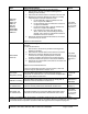
Original GNS 530W or GNS 430W is Reinstalled
No configuration is required.
Replacement GNS 530W or GNS 430W is installed
If the GNS 530W or GNS 430W unit is removed for repair and reinstalled, or if the unit is removed and
replaced with a different unit, then verify software and configure unit in accordance with the procedures
contained in Section 4 of the appropriate Modification Summary.
2.7.6.3 Return to service
Verify that the unit power-up self-test sequence is successfully completed and no failure messages are
annunciated.
NOTE
There are no special handling requirements for the GNS 530W and GNS 430W.
2.7.7 GA 35 Antenna
2.7.7.1 Removal
1. Gain access to antenna (see General Arrangement Drawing for location)
2. Remove the sealant surrounding the antenna
3. Remove the 4 screws that hold the antenna in place
4. Disconnect the coaxial cable.
2.7.7.2 Installation
To reinstall the GA 35 antenna:
1. Clean the antenna, doubler, and aircraft skin of any existing sealant or other material to ensure
adequate bonding.
2. Replace the o-ring (MS28775-116) between the fuselage skin and antenna.
3. Secure the antenna using the 4 8-32 screws and torque to 12-15 inch pounds.
4. Verify the resistance between the antenna and the aircraft metallic structure that forms the
ground plane is equal to or less than 2.5 milliohms per mating surface.
5. Using sealing compound (AMS-S-8802), run a bead of sealant along the antenna where it meets
the aircraft skin. Ensure the antenna connectors do not become contaminated with sealant.
6. Reconnect the coaxial cable to the antenna connector and ensure it is secure.
2.7.7.3 Return to service
Verify proper operation by successful completion of the self test of the interfaced GNS 530W or 430W.
NOTE
There are no special handling requirements for the GA 35.
2.7.8 GMA 347 Audio Panel
2.7.8.1 Removal
To remove the unit from the rack, turn the hex wrench counterclockwise until it disengages from the rack.
2.7.8.2 Installation
The GMA 347 unit is installed in the rack by sliding it straight in until it stops, about 1 inch short of the final
position. Insert the hex drive tool into the access hole at the bottom of the unit face. Rotate the hex tool
clockwise while pressing on the bezel until the unit is firmly seated in the rack.
Original GMA 347 is reinstalled
No configuration is required.
Replacement or repaired GMA 347 is installed