TR-1 Gold Owner’s Manual 906-2000-00 RevH 101507
Thank You Your purchase of this TR-1 Gold outboard management system enters you in the prestigious fraternity of anglers who count on TR-1 to control their outboard kickers. TR-1 Autopilots is dedicated to creating the finest controls and guidance systems for the best in boating and fishing. TR-1 Gold represents that effort. Enjoy your best fishing partner ever. We’re sure you will agree it is worth its weight in GOLD.
Safety You are responsible for the safe and prudent operation of your vessel. Your TR-1 Gold Autopilot is a tool that will enhance your capability to operate your boat and catch fish. It does not relieve you from the responsibility for safe operation of your vessel. You must avoid hazards to navigation and never leave the helm unattended. You must always be prepared to promptly regain manual control of your kicker. The autopilot and the throttle actuators can fail hard over.
TR-1 Gold Autopilot System Parts List Electro-Hydraulic unit……………….……. 120-2100-00 Kinked tubing with tie wrap………………. 3 ea. Truss head machine screws #8-32x 3/4 3 ea. Lock washer nuts #8-32……………… 3 ea. Truss head sheet metal screws #8 x 3/4 Sensor Ball Unit……………………………….…….. 120-2200-00 Sensor Ball Bracket …………………………………. 3 ea. Pan head machine screws #8-32 x 1”………… 3 ea. Lock washer nuts #8-32………………………… 3 ea. Pan head sheet metal screws #8 x 1”………… Sensor Ball Capture Cage...………………………….
Handheld/Remote Unit...…………………………. 120-2020-00 Cylinder Mounting Kit………………… (Motor Specific) 18 feet Hydraulic Hose………………………………… 120-0013-01 Steering Cylinder………………………………………... 120-0900-00 Throttle Actuator ( Motor Specific)………………………. 1 pt.
TR-1 Gold Specifications E-H unit 6.5”H x 7” W x 5” D Sensor Ball 3.6” Dia. Cable length 18’ Remote 5”x 2.5”x 1” Cable length 18’ Deckmount/Tach 5/8”x 2” Cable length 6’ Battery Cable Cable length 9’ Fluid 1 pt. BioSOY Oil Supply Voltage 11.5 – 14.0 VDC Maximum Current 12 Amperes Inline Fuse ATO 20 Amp Operating Ambient Temperature 20 – 120 deg F 8 lb 2 lb 1 lb 1 lb Introduction This manual comprises two major sections.
x Access The Electrohydraulic Unit is the place where all the components connect together and the place where fluid is added and fluid level is checked. Leave room for service loops in the cables and hoses. The Deckmount switch should be easy to reach with your free hand when your other hand is on the kicker tiller. This can be done after the initial turn on blinking setup is complete.
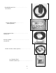
System Layout Handheld/Remote Sensor Ball: Mount in front 1/2 of boat. Throttle Actuator Mounts on carburetor on motor. GPS connection NMEA 0183 1 2 3 Battery 12V 4 Tach sensor wire:Attaches to spark plug wire on kicker. Electrohydraulic Unit: Mount near transom. Deckmount On/Off switch: Mounts near kicker motor, near transom. Cylinder Cylinder Mounting Bracket: Mounts on Motor lower end.
Tools You should gather the following tools before beginning installation. See throttle and cylinder supplements for any additional tools that may be needed for your application. Tools Power Drill #1 Phillips screw driver .125 (1/8) or 3.17 mm dia. drill .469 (15/32) or 11.90 mm dia. drill Roll of masking tape Rags Knife Pliers Silicone RTV Loctite or similar product Electrical grease compound (Dow Corning #4) Fig .
Mounting Hydraulic Unit Step Two (Locking unit in place) Fig. 6 Floor Mount: Set the unit on the floor in front of screws. Slide the left side back and engage the notch between the hose fittings around the left hand screw. Pivot the unit on the left hand screw counter clockwise until the notch under the electronics box on the right hand side is engaged and the remaining hole you drilled lines up with the hole in the bottom tab of the right hand bracket.
Installation of the Sensor Ball The Sensor (Compass) Ball needs to be mounted forward of the center of your boat. Make sure you mount it away from magnetic disturbances (stereo speakers, wiper motors, anchors). You will need to calibrate your compass on the water after installation of system and before you use the autopilot. Step one (Mounting the Sensor Ball) Hold the mounting bracket in the desired position and drill through the holes into the mounting surface.
Step 3 (Adjusting Sensor Ball) Readjust the ball if necessary and fix it in position by tightening the thumbscrew. See Fig 9-A. Make sure that the wires from the Sensor Ball are pointing straight down out the bottom; otherwise the sensor ball will not work properly. See Fig. 9-B Fig. 9-A Fig. 10-a Fig. 9-B Note: It is important to match your ECU wiring configuration to the picture. Just remember to always plug into matching numbers from the wire to the ECU. Fig. 10-b Run the wire back to the E-H unit.
Installation of the Deckmount and Tach Step One: (Deckmount) If the material you wish to mount the Deckmount switch in is less than ¼” thick: Drill a hole 15/32 Diameter perpendicular to the surface. Unscrew the bezel from the switch and leave one washer on the neck. Put the switch button, with washer, through the hole from below. Screw the bezel on to the top and your done. Refer to Fig.11 Fig.
Installation of the Handheld/Remote Connect the Remote cable to the ECU unit at connector number 3. Strain Relieve the cable. One place to do this is the bottom right hand side of the ECU unit. See Fig. 12. This will help protect the Remote cable from being pulled out of the connector on the ECU unit and possibly damaging unit. If you need to drill a hole in the boat for the cable be sure to put a grommet in the hole to protect cable from the sharp edges. Fig.
Connect and Fill the Hydraulic System Before you start……… x As with all hydraulic systems, it is very important to keep any dirt or debris from entering the system. x If you haven’t already, loosen the steering tension adjustment on your motor to the minimum setting. The motor should turn very easily. (If necessary refer to your outboard motor’s owner’s manual). x The fittings in the electro hydraulic unit (Pump unit) and the Cylinder are barbed hose fittings.
Step Three Arrange the hose at the cylinder end so that none will kink and they are hanging free. Put a piece of tape on the right hose at the cylinder end to identify it. You will need to know this when it’s time to connect the hose to the cylinder. See Fig.14. Step Four Fig. 14 Get into the boat close to the E-H unit. Bring the Remote Handheld, fluid, and some rags. Remove the screw that locks the E-H unit in place so that you can move the unit around.
Step Six (Fill Cylinder) Fig. 16 You will need the motor in the down position and the cylinder fittings pointing straight up. Disconnect the rod end of the cylinder from its mount. Find the kinked piece of tubing that you removed in step one. Remove the tie wrap and cut the tubing in half. Push one half on each cylinder barbed fitting. Open the fluid bottle. Insert pieces of tubing into the fluid. They need to go to the bottom of the bottle.
Step Eight (Check hose fit) Check to see that the hose is free to move back and forth with motor. Tie wrap as necessary to hold hose in place. See Fig. 18 Step Nine (Hose Clamp) Place hose clamps over hose and fittings at cylinder end. Fig. 18-a Step Ten (Top off the system) Manually turn the motor back and forth several times. Air bubbles trapped in the tubing may cause the fluid level in the tank to surge when the tiller is moved fast.
Introduction to Operation and Adjustments This section of this document provides you with information that will let you take advantage of your TR-1 Gold autopilots' capabilities. We have made every effort to minimize the pain in getting you up to speed as a user of the TR-1, however, programmable devices such as your TR1, are often difficult to learn to use and to program. We recommend that you do not take your fishing tackle with you on your first trip with your new autopilot.
6. Man Overboard. The autopilot will execute a turn to the reciprocal course and pass near the maneuver initiation point. 7. GPS steering. (Some GPS units may not support these features.) 7a. The autopilot will steer to a waypoint or series of waypoints. 7b. The autopilot will orbit a waypoint. 7c. The autopilot will steer a 3 leaf clover pattern over a waypoint. 7d. The autopilot will steer a spiral search pattern around a waypoint. 7e. The autopilot will steer to constant course over ground. 8. Reverse.
Power On/Off (Deckmount Switch) Turn power on by pressing and releasing the Deckmount switch. Turn the power off by pressing and holding the switch down until the Deckmount switch light has extinguished (about four seconds). Power on is indicated by illumination of the Deckmount switch button and the STBY LED on the Hand Held. Both the Deckmount switch light and remote STBY LED will blink for about 30 seconds after turning power on.
Change Heading with RCAH(RCAH) Change Heading While in Autopilot You can steer to a new heading with the Straight Right Arrow and Straight Left Arrow buttons. Momentary presses of either of these buttons will cause the pilot to alter the heading by one degree per press. For example, pressing the Straight Left Arrow button five times will cause the heading to be changed by 5 degrees to the port. Holding either of these buttons down causes the pilot to turn the rudder so as to make a port or starboard turn.
GPS Steering GPS The GPS steering functions are not guaranteed to work with all GPS systems. Each manufacturer of GPS equipment puts his own spin on how to assemble the data on the NMEA data bus. Sometimes the data on the bus will not conform to the needs of the autopilot. The autopilot expects to see, at least, the NMEA data sentences $GPRMB and $GPRMC at 4800 baud. These sentences are the minimum recommended data to be transmitted when there is an active waypoint.
Steer To Waypoints (GPS Steering) If you press and release the GPS (Select Load) button when the autopilot is in heading hold and the GPS has an active route, the pilot will steer to the selected waypoint. If you are more than 1000 ft. off the courseline the pilot will steer directly at the waypoint and not try to remove crosstrack error. Return to heading hold by pressing one of the Straight Arrow buttons.
Search Pattern (GPS Steering) To do an outward spiraling search from a waypoint, setup the special function buttons for search patterns. (See page 28 Selecting Special Functions) When you are near the waypoint you want to search from, select “go to” this waypoint on your GPS. With the pilot in heading hold, press and release the GPS (Select Load) button and then press and release one of the Bent Arrow buttons.
Reverse The autopilot will attempt to perform any of its steering functions when the boat is backing in reverse gear. To engage the system in reverse: 1) Start from Standby. 2) Press and hold the GPS (REV) button. 3) Press and release the Auto/Stby button. 4) Release the GPS (REV) button.
Throttle Up/Down Throttle Up/Down Increase throttle by pressing the Up Arrow button. Decrease throttle by pressing the Down Arrow button. The electric throttle runs in parallel with the tiller throttle, this means that you can't reduce the RPM with the electric throttle if the tiller throttle is set high. It is best to always run with the tiller throttle set to idle. Be careful to set the electric throttle and tiller throttle to closed position before starting your outboard.
Selecting Special Functions When you select special functions, by the methods described below, you are simply choosing which function is to be executed by the pilot when you push one of the tree special function buttons. The Idle/Resume button is programmable to provide either Idle/Resume or MOB or Zigzags (other). The Bent Left Arrow button is programmable to provide either Steps or Circles or Remote Steer.
How to Make System Changes with Setup 1. Autopilot must be in Heading Hold or Standby Mode before selection process can start. (AUTO LED solid on or STBY LED solid on. No other LED's on.) 2. Press and release the Setup Button. The Setup LED will illuminate to indicate the system is ready to take setup commands (button pushes). 3. Make selection of the Setup Function you want to use by pressing and releasing the buttons labeled 1 through 9 until the appropriate LED's are lit.
Table of Setup Codes Tachometer Codes Setup Action Code # Range of Settings or Responses Default Stby Safety Monitor 349 2 settings on, off, defaults to on every power up on Tach on/off 34 2 settings on, off on Show RPM 36 Hold Down Select Load Button: 1000’s blink on up Arrow 100’s blink on down Arrow Throttle Codes Throttle Speed 24 1 lowest speed, 10 highest speed 5 Throttle Delay 25 1 least delay, 10 most delay 5 Hydraulic Codes Reverse Hoses 259 2 settings normal up arrow lit,
Navigation Function Codes Navigation Function Codes Setup Action Setup Action Navigation Gain Navigation Navigation Function Gain GainCodes Navigation Trim Navigation Trim Gain Use Synthetic XTE Setup Action Use Synthetic Change Sign ofXTE XTE Navigation Gain Change Sign ofNorth XTE Use Magnetic Navigation Trim Gain UseNorth Magnetic North Set Use Synthetic XTE Set North Change Sign of XTE Use Magnetic North Enable Checksums Set North Enable Checksums Code # Code 15 # 15 16 16 37 Code # 37 18 15 18 39 16 3
Code 35. Since the boat dynamics change with RPM the autopilot retunes itself as it sees the RPM change. Most boats will work well with the mild setting. The easiest way to set the speed schedule is to first get tuned up and working well at low speed, then run at high speed. 1) If steering response is sluggish, increase code 35. 2) If the steering response is oscillatory, decrease code 35. Code 37.
Compass Calibration and Tuning your Autopilot Your autopilot needs to be “tuned” to your boat and motor configuration. This is the most difficult part of getting your pilot running the best it can. Have patience and don’t even try to do this until you have some time on a nice calm day. Follow the directions below. 1. Calibrate your compass. The autopilot compass is made with a fluxgate.
3. Tune the feedback gains. Start from [Standby] mode. (The STBY light should be lit on the handheld.) • Press the [Setup] button and press and light up code 2 (Number 2 LED on the handheld) - this is the rudder gain adjustment code. Run your boat in a straight line at 1/3 to 1/2 full speed and engage the pilot by pressing the Auto/Stby button. Don’t expect to see good performance yet.
4. Set North: You must do this, if the autopilot is connected to the GPS. To run a GPS course requires that the autopilot compass is in agreement with the GPS’s course estimate. You need to set North with the pilot in standby mode. Do not set North except in calm sea’s and un-accelerated conditions. You should be running at a reasonably high speed, it won’t hurt to be running on plane with your main engine. With your GPS turned on and setup code 48 selected, press and hold the GPS (Select Load) button.
Well Tuned Response Heading 8 6 4 2 0 0 2 4 Time 6 8 10 The objective of tuning is to set the gains so as to elicit a response with a shape like this that reaches the 5 degree heading in as short of a time interval as possible. You know that you have reached this tune when attempts to increase the Rudder Gain or Decrease the counter rudder gain results in oscillations in heading.
Heading Rudder Gain Effects 8 Too Low 6 Too High 4 2 0 0 2 4 Time 6 8 10 The Rudder Gain Effects plot shows that too low a Rudder Gain will make the heading response slow and sloppy, if the Rudder Gain is turned down much lower the heading response will become unstable (do everything but hold heading).
Limited Warranty This TR-1 product is warranted to be free from defects in materials or workmanship for one year from the date of purchase. Within this period, TR-1 will, at its sole option, repair or replace any components that fail in normal use. Such repairs or replacement will be made at no charge to the customer for parts or labor, provided that the customer shall be responsible for any transportation cost.