Corporate Headquarters GarrettCom, Inc. 47823 Westinghouse Dr. Fremont, CA 94539 Phone (510) 438-9071 Fax (510) 438-9072 Website: http://www.GarrettCom.com MagnumFT14 and FT14H email support@garrettcom.com 10Mb/s Media Converters Installation and User Guide www . GarrettCom . com www . GarrettCom .
FT14 and FT14H 10Mb Media Converters Installation and User Guide (09/04) Magnum™ FT14 and FT14H 10Mb/s Media Converters Installation and User Guide Part #: 84-00134 Rev. A (09/04) Trademarks Ethernet is a trademark of Xerox Corporation NEBS is a trademark of Telcordia Technologies UL is a registered trademark of Underwriters Laboratories GarrettCom, Magnum and Personal Switch are trademarks and Personal Hub is a registered trademark of GarrettCom, Inc.
FT14 and FT14H 10Mb Media Converters Installation and User Guide (09/04) Federal Communications Commission Radio Frequency Interference Statement This equipment generates, uses and can radiate frequency energy and if not installed and used properly, that is in strict accordance with the manufacturer's instructions, may cause interference to radio communication.
FT14 and FT14H 10Mb Media Converters Installation and User Guide (09/04) Contacting GarrettCom, Inc Please use the mailing address, phone and fax numbers and email address listed below: GarrettCom, Inc. 47823 Westinghouse Dr. Fremont, CA 94539 Phone (510) 438-9071 Fax (510) 438-9072 Website: http://www.GarrettCom.com Email: support@garrettcom.com www . GarrettCom .
FT14 and FT14H 10Mb Media Converters Installation and User Guide (09/04) TABLE OF CONTENTS 1.0 1.1 1.2 2.0 2.1 2.2 2.3 2.4 2.5 2.6 3.0 3.1 3.2 3.3 3.4 3.5 Page SPECIFICATIONS ............................................................................... 1 Technical Specifications ..................................................................... 1 Summary of models and descriptions: .................................................... 7 INTRODUCTION ...................................................
FT14 and FT14H 10Mb Media Converters Installation and User Guide (09/04) 3.6 Connecting Ethernet Media ............................................................... 34 3.6.1 Connecting Twisted Pair (RJ-45 ports)...................................... 34 3.6.2 Connecting Fiber Optic mm, sm (half- and full-duplex) ......... 35 3.6.3 Power Budget Calcs for Fiber Media Magnum FT14-series...... 37 4.0 OPERATION ....................................................................................... 39 4.
FT14 and FT14H 10Mb Media Converters Installation and User Guide (09/04) Revisions Rev A 09/04: Minor updates on UL Requirements, power supplies Rev A 06/04: Minor updates on Agency approvals and power supplies Rev A 05/03: Initial release of this user manual for FT14 and FT14H GarrettCom, Inc. reserves the right to change specifications, performance characteristics and/or model offerings without notice. www . GarrettCom .
FT14 and FT14H 10Mb Media Converters Installation and User Guide (09/04) 1.0 SPECIFICATIONS 1.1 Technical Specifications Model FT14, FT14H multi-mode and single-mode Performance: Data Rate: 10 Mbps (IEEE 802.3), half duplex mode Network Standards: Ethernet: Ethernet V1.0/2.0 IEEE 802.3: 10BASE-T, 10BASE-FL IEEE 802.3, (Magnum Media Converters are physical layer standard Ethernet products, and operate independently of all software.
FT14 and FT14H 10Mb Media Converters Installation and User Guide (09/04) Maximum Standard Ethernet Segment Lengths: 10BASE-T (twisted pair): 100 m (328 ft) 10BASE-FL Fiber optic : 2.0 km (6,562 ft) 10BASE-FL Single-mode Fiber optic: 10.0 km (32,810ft) Note for single-mode: HDX collision domain limits may restrict distances to about 5km. Note: Magnum Media Converters DO NOT support full length Ethernet segments. See Section 3.2 of this manual for media lengths and segment distance calculations.
FT14 and FT14H 10Mb Media Converters Installation and User Guide (09/04) Ambient Relative Humidity: 5% to 95% (non-condensing) UL 2043 tested for above-the –ceiling (plenum) installation Conformal coating (humidity protection) option, request quote.
FT14 and FT14H 10Mb Media Converters Installation and User Guide (09/04) 100-240V AC at 50-60Hz, for high temp. with built-in IEC320 connector for “-Hi” DC to unit: “Hi” international model 9V DC, 2.5mm jack, center +ve, 6ft. cord Power Supply ( DC Direct): built-in terminal block for +, -, ground. The 9V DC jack is also present. 9V DC internal (range of 7.5 to 15V DC) 24V DC internal (range of 18 to 36V DC) -48V DC internal (range of 36 to 60V DC) Power Consumption: 1.5 watts typical and 2 watts max.
FT14 and FT14H 10Mb Media Converters Installation and User Guide (09/04) RJ-45 Port: Modular 8-Pin female, with “cross-over” up-link switch Fiber Port: Fiber optic (standard ST type) Packaging: Enclosure: Rugged sheet metal (Steel). Dimensions, Media Converter unit: Height x Width x Depth FT14 and FT14H: 3.5 in H x 3.0 in W x 1.0 in D (8.9 cm x 7.6 cm x 2.5 cm) Weight: all FT14 and FT14H mm and sgl.mode models: 4.6 oz.
FT14 and FT14H 10Mb Media Converters Installation and User Guide (09/04) Metal Mounting clips for panel mounting : included DIN-Rail mounting option: Model # DIN-RAIL MC2 (see Section 3.4) Rack-mount option: MC14-TRAY, see http://www.garrettcom.com/mc_tray.htm Mean Tine Between Failure (MTBF) – 15+ years, Telcordia (Bellcore) Method Agency Approvals and Standard Compliance: UL LISTED (UL 60950), CUL, CE Emissions meet FCC Part 15, Class A NEBS L3 and ETSI compliant H Model: IEEE P1613 Env.
FT14 and FT14H 10Mb Media Converters Installation and User Guide (09/04) 1.
FT14 and FT14H 10Mb Media Converters Installation and User Guide (09/04) 2.0 INTRODUCTION This section describes the FT14 and FT14H models, including appearance, features and typical applications. 2.1 Inspecting the Package and the Product Examine the shipping container for obvious damage prior to installing this product; notify the carrier immediately of any damage which you believe occurred during shipment or delivery.
FT14 and FT14H 10Mb Media Converters Installation and User Guide (09/04) Remove the Magnum Media Converter from the shipping container. Be sure to keep the shipping container should you need to ship the unit at a later date. In the event there are items missing or damaged contact your supplier. If you need to return the unit use the original shipping container. Refer to Section 5 Troubleshooting, for specific return procedures. 2.
FT14 and FT14H 10Mb Media Converters Installation and User Guide (09/04) The FT14 regular-package units are for office and wiring closet environments and use an external AC power supply. A metal case with convection cooling is featured.
FT14 and FT14H 10Mb Media Converters Installation and User Guide (09/04) Operation may be in 0° to 50°C ambient temperature. The units can be mounted securely on a closet wall or metal cabinet, or by using the metal panel mounting clips included. The FT14H Hardened unit features a sealed metal case which is also used as a heat sink. No air inflow is required for cooling, so the FT14H resists dust, dirt, moisture, smoke and insects, and is plenum rated.
FT14 and FT14H 10Mb Media Converters Installation and User Guide (09/04) All units are compatible with Ethernet V 1.0 / 2.0 specifications and comply with IEEE 802.3 standards. A L R X/ A C T LINK PWR LINK RX/ACT Twisted Pair COPPER GarrettCom Ethernet at its Best X UP LINK = L 10 Mb/s P Magnum FT14 10Mb/s Media Converter R X 9VDC (10BASE-T) FIBER TX www. GarrettCom .com www . GarrettCom .
FT14 and FT14H 10Mb Media Converters Installation and User Guide (09/04) The up-link (or crossover) switch on the RJ-45 port simplifies cable installation. All fiber models operate in transparent full- or half-duplex mode, supporting matched sets of either mode type, i.e., attached devices are either both full-duplex or both half-duplex. Magnum FT14-series 10Mb Media Converters are designed for quick and easy installation even in very tight spaces.
FT14 and FT14H 10Mb Media Converters Installation and User Guide (09/04) extended temperature power supply AC/DC (External/Internal) to qualify for uncontrolled and Industrial application. Each converter features two full sets of LEDs that convey essential diagnostic and status information at any angle. See Section 4.1 and 4.4, for power supply and LED function specifications. All of the Magnum FT14-series Media Converters comply with the IEEE 802.
FT14 and FT14H 10Mb Media Converters Installation and User Guide (09/04) 2.3 Features and Benefits Reduces Network Costs Magnum Media Converters offer the ideal solution to efficiently and inexpensively connect Twisted Pair with 10Mb Fiber media within an expanding Ethernet network where full repeaters are not required.
FT14 and FT14H 10Mb Media Converters Installation and User Guide (09/04) Two sets of LEDs for viewing status from any angle. Each FT14 Media Converter is equipped with a two sets (front and side) of LEDs to provide status information when viewed at any angle or mounting arrangement, rack-mount (MC14- Tray) or wall-mount.
FT14 and FT14H 10Mb Media Converters Installation and User Guide (09/04) Qualified to use for temperature un-controlled “outdoor” application The Magnum FT14H Hardened version of media converter supports the ambient temperature rating up to –40C to +75C for DC options model, which qualified for un-controlled “outdoor” application.
FT14 and FT14H 10Mb Media Converters Installation and User Guide (09/04) 2.4 Applications for FT14’s and hardened FT14H’s The primary function of a 10Mb Ethernet Media Converter is to permit two different 10Mb media types to coexist inexpensively within the same network by allowing data to be transmitted and received between different media types.
FT14 and FT14H 10Mb Media Converters Installation and User Guide (09/04) In this application, in a Industrial environment where extended temp. supported units is a requirement, the existing Twisted pair network can be easily connected to longer distance through fiber media using Magnum FT14 or FT14H 10 Mb media converters. 10Base-T Ethernet Segment RX/ACTLink Pw Link RX\ACT ACT TWISTED PAIR FIBER Magnum TB14 Lin k UP LINK Media Converter RX\ACT Lin k RX 9VDC .
FT14 and FT14H 10Mb Media Converters Installation and User Guide (09/04) 2.5 Full / Half-duplex capability For 10Mb FT14-series Media converters, the twisted-pair to fiber combination is capable of full-duplex (i.e., simultaneously transmitting and receiving on the same cable segment) operation.
FT14 and FT14H 10Mb Media Converters Installation and User Guide (09/04) networks, the LINK signal on a managed switch (or hub) port is used as an indicator that the attached cable segment is installed and operable. The network manager, using the SNMP agent, can troubleshoot the cabling by examining the LINK status on each port. This works fine as long as all of the cabling is twisted pair.
FT14 and FT14H 10Mb Media Converters Installation and User Guide (09/04) the cable attached to a managed switch port. The Link-Pass-through in the FT14H models provides the LINK “see-through” feature desired for managed networks. On the FT14H models, either both LINK LEDs are lit or neither is lit. And, the FT14 and FT14H’s both operate in transparent half- and full-duplex mode.
FT14 and FT14H 10Mb Media Converters Installation and User Guide (09/04) 3.0 INSTALLATION This section describes the installation of the Magnum FT14-series Media Converters, including location, segment distance calculation and media connection. 3.1 Locating the Media Converter Unit All the FT14-series operate in transparent halfand full-duplex mode. For half-duplex traffic, the FT14-series work correctly but do not detect or indicate collisions.
FT14 and FT14H 10Mb Media Converters Installation and User Guide (09/04) Velcro strip may be used for mounting the unit on a vertical surface such as a wall or cabinet, or for securing the unit on a table-top or shelf. Alternatively, metal mounting clips and screws are included for a rugged and secure mounting in any orientation. Installation of the Magnum FT14 and FT14H Media Converters is a simple procedure.
FT14 and FT14H 10Mb Media Converters Installation and User Guide (09/04) 3.2 MC14-TRAY for Rack Mounting of FT14 and FT14H Media Converters For 19” rack-mounting of Magnum FT14-series Media Converters, a rack-mount tray is available, MC14-TRAY. The Media Converter units are mounted with their RJ-45 port and DC power jack in the back, with either fiber or BNC cable in the front. Any mix of the FT14-type Media Converters may be placed on a tray, up to a maximum of 16 units.
FT14 and FT14H 10Mb Media Converters Installation and User Guide (09/04) specific to the “14”-series, and do not permit other models). A typical installation of the model MC14-TRAY, 19” rack-mount tray will hold a few (often three to eight) 14-series Media Converters, with their power supplies plugged into power strips (not included) in the rear area of the tray. Metal mounting screws in the bottom-front hold the Media Converters firmly in place.
FT14 and FT14H 10Mb Media Converters Installation and User Guide (09/04) MC14-TR+PS9 and 16 units of Fiber media converters for MC14-TR+PS9X2. The MC14-TR+PS9X2 Model has two groups of eight units per power supply. These models are equipped with autoranging AC input to the power supplies for use worldwide. (The MC mounting spaces of the MC14 -TR models are specific to the Magnum 10Mbps (FT14 and TB14) and 100Mb (14E) series, and do not permit other models to be put in the tray). www . GarrettCom .
FT14 and FT14H 10Mb Media Converters Installation and User Guide (09/04) The side-view picture shown here (above) is an example of an installation of the model MC14-TR+PS9, 19” rack-mount tray, holding a few 10Mbps FT14’s and 100Mb 14E Media Converters, each with their power input plugged into the built-in common AC power supply in the rear area of the tray. (PS units that come with the MC’s are not used).
FT14 and FT14H 10Mb Media Converters Installation and User Guide (09/04) The metal DIN-Rail mounting hardware is optional and needs to be ordered as a separate item, e.g. Model # DIN-RAILMC2. It comes with four screws to attach the bracket to the MC unit. The rail clip is springloaded with a pull-up latch at the top for easy “snap-on” attachment and removal. The Magnum FT14 Models with “HR” have 24VDC power, and have the DINRail-MC2 bracket included and assembled with the MC unit at the factory.
FT14 and FT14H 10Mb Media Converters Installation and User Guide (09/04) order to maintain optimum network performance. (See also Technical Specs, Maximum Standard Ethernet Segment Distances, Section 1.1 of this manual.) When installing the Magnum FT14-series Media Converter, it is important to consider the combined overall segment length of both of the attached media types. The overall segment length is calculated by adding together the segment lengths on both sides of the Magnum Media Converters.
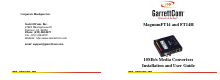
FT14 and FT14H 10Mb Media Converters Installation and User Guide (09/04) Y = 55m A L R X/ A C T LINK PWR LINK RX/ACT Twisted Pair COPPER (10BASE-T) FIBER = X GarrettCom Ethernet at its Best X UP LINK = L Fiber optic - ST Connector (10BASE-FL and FOIRL) Magnum FT14 10Mb/s Media Converter 9VDC .0.3AMP A P 10 Mb/s RX TX X = 780m www. GarrettCom .com Connectivity between Fiber and TP Ethernet Media. www . GarrettCom .
FT14 and FT14H 10Mb Media Converters Installation and User Guide (09/04) Media Distance Formula for Magnum Media Converters: X% + Y% < 100% Where X = The segment distance on one side of the Magnum Media Converter divided by the Standard Maximum Media Distance for that media type, x 100%.
FT14 and FT14H 10Mb Media Converters Installation and User Guide (09/04) allowable distance for UTP 10BASE-T media (100 m) [55/100 x 100% = 55%]. The total of the two percentages (39% + 55%) is 94%, which is allowable. Note 1: Where more than one media converter is used in one segment run, the percentages for all of the cabling lengths in the run must be added together and must not exceed 100%.
FT14 and FT14H 10Mb Media Converters Installation and User Guide (09/04) 3.6 Connecting Ethernet Media Connecting Ethernet media to the Magnum FT14 Series Media Converter is very simple and straightforward. Using proper media segment, simply attach the cable end to the appropriate connector. See Sections 4.4 for details of the LEDs on the media converter models. 3.6.
FT14 and FT14H 10Mb Media Converters Installation and User Guide (09/04) 2. Connect the other end of the cable to the corresponding device. Use the LINK LED to ensure proper connectivity by noting that the LED will be illuminated when the units are powered and proper connections established. If the LINK LED is not illuminated, change the setting of the up-link switch (See Section 4.6 for up-link switch information.
FT14 and FT14H 10Mb Media Converters Installation and User Guide (09/04) Fiber Cable Type cable diameter * Max. length Wavelength Multi-mode fiber 50/125, 62.5/125. 2km 850 nm cable diameter * Max. length Wavelength Fiber Cable Type Single-mode fiber 2/15 - 8/60 10km 1300 nm * xx/yy are the diameters of the core and the core plus cladding respectively The values shown are typical values Procedure for connecting multi-mode and single-mode fiber cables: 1. 2. 3. 4.
FT14 and FT14H 10Mb Media Converters Installation and User Guide (09/04) 5. 6. 3.6.3 The LINK LED corresponding to the fiber port on the front of the product will illuminate (for standard non-Link-Pass-through models) when a proper connection has been established at both ends (and when power is ON in the units at each end). If LINK is not lit after cable connection, the normal cause is improper cable polarity. Swap the fiber cables on the product connector to remedy this situation.
FT14 and FT14H 10Mb Media Converters Installation and User Guide (09/04) The following data has been collected from component manufacturer’s (HP’s and Siemens’) web sites and catalogs to provide guidance to network designers and installers. Fiber Port Module Speed, Note: The worst-case OPB of the fiber link must be greater than the fiber cable’s passive Attenuation. Std. Wave Cable X’mitr R’cvr Worst Worst* typical typical* km Size Output Sens. OPB, distance OPB, distance Std.
FT14 and FT14H 10Mb Media Converters Installation and User Guide (09/04) 4.0 OPERATION This section describes the operation of the Magnum FT14 and FT14H, 10Mb Media Converters, including power supply requirements, up-link switch functionality, and a description of all LEDs. 4.1 Power Requirements, Power Supply Types for FT14 and FT14H Magnum FT14 Media Converters are power-efficient and can work with an external AC power supply. Magnum FT14 Media Converters require a nominal 9VDC input.
FT14 and FT14H 10Mb Media Converters Installation and User Guide (09/04) The FT14H Hardened media converters are designed to provide reliable operation, withstand higher temperature environments, and provide the direct DC power choices to the user to deploy in uncontrolled temperature environments. 9VDC 24VDC -48VDC The Internal 9V DC (8 – 15V DC) has a built-in terminal block for +, -, ground. The 9V DC jack is also present.
FT14 and FT14H 10Mb Media Converters Installation and User Guide (09/04) Note: When connected to a -48 V centralized dc source these products are to be installed only in Restricted Access Areas (dedicated equipment rooms, electrical closets or the like). 4.2 Powering the FT14H (DC Direct) with 12V, 24V or –48V DC power input Each Magnum FT14H is equipped with a Direct DC power supply, and have built-in screw terminals for secure attachment of the power leads.
FT14 and FT14H 10Mb Media Converters Installation and User Guide (09/04) is also present and optionally can be used with an external AC power supply. DC Power Terminals: “+”, “-”, floating GND: Terminal for “earth” or ground wire connection to the FT14H chassis Input Voltage: 7.5 - 15V DC (9V DC) 18 – 26V DC (24V DC) 30 – 60V DC (-48V DC) Input current: 0.8 amp max.(9V DC) 0.4 amp max.(24V DC) www . GarrettCom .
FT14 and FT14H 10Mb Media Converters Installation and User Guide (09/04) 0.2 amp max.(-48V DC) Power Consumption: 1.5 watts typical, 2 watts maxm. 4.3 FT14H, DC-powered, -48VDC, 24VDC and 9VDC Installation This section describes the proper connection of the -48VDC leads (or 24VDC, 9VDC leads) to the Direct DC power terminal block on the Magnum FT14H hardened media converter (as shown in Figure above).
FT14 and FT14H 10Mb Media Converters Installation and User Guide (09/04) terminals are identified as positive (+) and negative (-), and they are floating inside the unit so that either of the terminal may be grounded by the user if desired. The chassis is “earth” or ground (GND). The connection procedure is straightforward. Simply insert the DC leads to the FT14H’s power terminals, positive (+) and negative (-) screws. The use of Ground (GND) is optional; it connects to the FT14H chassis.
FT14 and FT14H 10Mb Media Converters Installation and User Guide (09/04) 4.4 Dual LEDs, front-panel and side-panel (Magnum FT14 and FT14H) Description LED PWR/P Illuminates GREEN to indicate power applied. LINK/L (TP) Illuminates GREEN, Steady ON when both attached cable segments are operational at the other end. LINK will turn off in the event connectivity is lost between the ends of the twisted pair segment or a loss of power occurs in the unit or remote device.
FT14 and FT14H 10Mb Media Converters Installation and User Guide (09/04) 4.5 Up-Link (Cross-over) Switch The FT14 and FT14H Media Converter is equipped with an Up-Link slide switch. When set to the UP position (X), the Media Converter is wired with cross-over functionality for direct uplink to a network hub, switch or concentrator. When set to the DOWN position (=), the Magnum RJ45 up-link user device (=) Media Converter is wired for normal twisted-pair connection to a user node device.
FT14 and FT14H 10Mb Media Converters Installation and User Guide (09/04) 5.0 TROUBLESHOOTING All Magnum Ethernet products are designed to provide reliability and consistently high performance in all network environments. The installation of Magnum FT14-SERIESs 10 Mb/s Media Converters is a straightforward procedure (see INSTALLATION, Section 3.0); the operation is also straightforward and is discussed in Section 4.
FT14 and FT14H 10Mb Media Converters Installation and User Guide (09/04) 5.1 Before Calling for Assistance 1. If difficulty is encountered when installing or operating the unit, refer back to the Installation Section of the applicable chapter of this manual. Also check to make sure that the various components of the network are interoperable. 2.
FT14 and FT14H 10Mb Media Converters Installation and User Guide (09/04) 4. If the problem is isolated to a network device other than the Magnum FT14/FT14H 10 Mb/s Media Converters product, it is recommended that the problem device is replaced with a known good device. Verify whether or not the problem is corrected. If not, go to Step 5 below. If the problem is corrected, the Magnum FT14/FT14H 10 Mb/s Media Converters and its associated cables are functioning properly. 5.
FT14 and FT14H 10Mb Media Converters Installation and User Guide (09/04) 5.2 When Calling for Assistance Please be prepared to provide the following information. 1. A complete description of the problem, including the following points: a. The nature and duration of the problem; b. Situations when the problem occurs; c. The components involved in the problem; d. Any particular application that, when used, appears to create the problem; 2.
FT14 and FT14H 10Mb Media Converters Installation and User Guide (09/04) 3. It is useful to include other network equipment models and related hardware, including personal computers, workstations, terminals and printers; plus, the various network media types being used. 4. A record of changes that have been made to your network configuration prior to the occurrence of the problem. Any changes to system administration procedures should all be noted in this record. 5.
FT14 and FT14H 10Mb Media Converters Installation and User Guide (09/04) Product name Serial Number (or Invoice Number) Packing List Number (or Sales Order Number) Date of installation Failure symptoms, including a full description of the problem.
FT14 and FT14H 10Mb Media Converters Installation and User Guide (09/04) GarrettCom reserves the right to charge for the testing of non-defective units under warranty. Testing and repair of product that is not under warranty will result in a customer (user) charge. www . GarrettCom .
FT14 and FT14H 10Mb Media Converters Installation and User Guide (09/04) 5.4 Shipping and Packaging Information Should you need to ship the unit back to GarrettCom, please follow these instructions: 1. Package the unit carefully. It is recommended that you use the original container if available. Units should be wrapped in a "bubble-wrap" plastic sheet or bag for shipping protection. ( You may retain all connectors and this Installation Guide.
FT14 and FT14H 10Mb Media Converters Installation and User Guide (09/04) 4. Ship the package to: GarrettCom, Inc. 47823 Westinghouse Dr. Fremont, CA 94539 Attn.: Customer Service APPENDIX A: WARRANTY INFORMATION GarrettCom, Inc. warrants its products to be free from defects in materials and workmanship for a period of three (3) years from the date of shipment by GarrettCom.
FT14 and FT14H 10Mb Media Converters Installation and User Guide (09/04) This warranty will not be effective if, in the opinion of GarrettCom, the product has been damaged by misuse, misapplication, or as a result of service or modification other than by GarrettCom. GarrettCom reserves the right to make a charge for handling and inspecting any product returned for warranty repair which turns out not to be faulty.