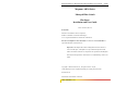
Magnum 6K16-Series Corporate Headquarters Managed Fiber Switch GarrettCom, Inc. 47823 Westinghouse Dr. Fremont, CA 94539-7437 Phone (510) 438-9071 Fax (510) 438-9072 Website: http://www.GarrettCom.com email support@garrettcom.com Two 6K16s mounted side-by-side on Tray Magnum 6K16V mounted vertically Hardware Installation and User Guide www . GarrettCom . com www . GarrettCom .
Magnum 6K16-Series Managed Fiber Switch Installation & User Guide (04/06) Magnum™ 6K16-Series Managed Fiber Switch Hardware Installation and User Guide Part #: 84-00136 (Rev. B) Trademarks Ethernet is a trademark of Xerox Corporation NEBS is a trademark of Telcordia Technologies UL is a registered trademark of Underwriters Laboratories GarrettCom, Magnum and Personal Switch are trademarks and Personal Hub is a registered trademark of GarrettCom, Inc.
Magnum 6K16-Series Managed Fiber Switch Installation & User Guide (04/06) Contacting GarrettCom, Inc Please use the mailing address, phone and fax numbers and email address listed below: GarrettCom, Inc. 47823 Westinghouse Dr. Fremont, CA 94539-7437 Phone (510) 438-9071 Fax (510) 438-9072 Website: http://www.GarrettCom.com email support@garrettcom.
Magnum 6K16-Series Managed Fiber Switch Installation & User Guide (04/06) Table of Contents.............................................................................. Page 1.0 SPECIFICATIONS ............................................................................... 1 1.1 Technical Specifications ...................................................................... 1 1.2 Ordering Information ........................................................................... 4 2.0 Introduction.............
Magnum 6K16-Series Managed Fiber Switch Installation & User Guide (04/06) OPERATION ....................................................................................... 40 4.0 4.1 Switching Functionality ..................................................................... 40 4.2 Status LEDs ....................................................................................... 41 4.3 Up-link Manual Switches set as (=) , for RJ-45 port only ................. 41 4.
Magnum 6K16-Series Managed Fiber Switch Installation & User Guide (04/06) Revisions 04/06: minor updates as PoE modules option added on Sec 5.2.10/11 10/05: minor updates as MDIX support added on all RJ-45 port modules 02/05: minor updates and tweaks on LC port module 07/04 : 6K16 carrier class managed switch has been added with 6K16V 01/04 : Added Section 3.5 (Alarm Contacts) and 3.7.1 (Console Port pins) 12/03: Updated Section 3.
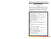
Magnum 6K16-Series Managed Fiber Switch Installation and User Guide 04/06) THE MAGNUM LINE Ethernet connectivity products "Designed and Manufactured in the USA" Overview GARRETTCOM, INC. OFFERS THE PREMIUM-QUALITY MAGNUM™ LINE OF ETHERNET LAN CONNECTIVITY PRODUCTS WITH INDUSTRY-STANDARD FUNCTIONALITY AND BUILT-IN FIBER CONFIGURABILITY. MAGNUM PRODUCTS ARE DESIGNED FOR USE IN DEMANDING CARRIER CLASS, INDUSTRIAL GRADE AND OEM APPLICATIONS WHERE RELIABILITY IS A PRIMARY CONSIDERATION.
Magnum 6K16-Series Managed Fiber Switch Installation and User Guide 04/06) 8 OR 9-PORT AND 4 OR 5-PORT PERSONAL HUBS, W/ MAN. UP-LINK SW. MEDIA CONVERTERS, 10MB AND 100MB SERIES ALL MEDIA COMBINATIONS, INCL. FIBER ST, SC, MM.
Magnum 6K16-Series Managed Fiber Switch Installation and User Guide (04/06) 1.0 1.1 SPECIFICATIONS Technical Specifications Performance Filtering / Forwarding Rate: Ethernet(10Mb):14,880 pps Fast Ethernet(100Mb): 148,800 pps Gigabit Ethernet(1000Mb): 1, 488,000 pps Switching Processing Type: Store and Forward with IEEE 802.
Magnum 6K16-Series Managed Fiber Switch Installation and User Guide (04/06) Fiber Single-mode connector types: Fiber Port, SC-type: Fiber optic single-mode, 100BASE-FX Fiber Port, LC-type Fiber SFF single-mode, 100BASE-FX Fiber Port, 1000BASE-FX, GBIC modules LEDs: Per Port (one set at the port, one set on rear top) 6K16V only Per Port (one set at the port) 6K16 LK: Steady ON when media link is operational ACT: ON with receiver port activity FDX/HDX: ON = Full-Duplex Mode OFF = Half-Duplex Mode 100/10: ON =
Magnum 6K16-Series Managed Fiber Switch Installation and User Guide (04/06) For DC internal power supplies at –48VDC, 24VDC and 125VDC, including Dual Source options (for continuity of operation when either of the DC input sources are interrupted), see Appendices B and C. Per-port MDI or MDIX on RJ-45 The copper daughter board has MDI-MDIX Auto-crossover on all the RJ-45 ports., and eliminate the use of cross-over cable between the devices.
Magnum 6K16-Series Managed Fiber Switch Installation and User Guide (04/06) 1.2 Ordering Information Magnum Managed Fiber Switch (16 ports max) MODEL DESCRIPTION Magnum 6K16V -Magnum 6K16V Managed Fiber Switch, base unit for vertical mounting. Worldwide AC power. May be configured with a selection of 10/100/1000 fiber and copper port connector types, 16 total ports max. Two metal brackets for vertical wall or panel mounting. Wire speed filtering and forwarding across all ports, 802.
Magnum 6K16-Series Managed Fiber Switch Installation and User Guide (04/06) fiber ports connector GBPMV-2OTX Two-port Gigabit 6K module for 6K16-Series Switches, provides two GBIC open transceiver port for a user-selectable GBIC transceiver module GBPMV-COTX One slot Gigabit 6K module for 6K16-Series Switches, uses one 6K16Series slot and provides one GBIC open transceiver port for a user-selectable GBIC transceiver module DIN-RAIL-VRM Set of two DIN-Rail holders for a secure vertical mount of a 6K16Series
Magnum 6K16-Series Managed Fiber Switch Installation and User Guide (04/06) Gigabit (1000Mb) module option for Magnum 6K16V 6KP5-G4RJ “G+2” module, w/one GBIC transceiver and four 10/100 RJ-45 connectors 6KP3-G2SC “G+2” module, w/one GBIC transceiver and two 100Mb 2km FX SC fiber ports connector GBPM-2OTX Two-port Gigabit 6K module for 6K16-Series Switches, provides two GBIC open transceiver port for a user-selectable GBIC transceiver module GBPM-COTX One slot Gigabit 6K module for 6K16-Series Switches, use
Magnum 6K16-Series Managed Fiber Switch Installation and User Guide (04/06) 6K PoE Modules with 48VDC Pass-Through Configuration options: only one A, B or C module slot of 6K-Series switch with 48VDC power input may be configured with a PoE Modules New P6KP8-RJ45 8 port PoE module for 6ks with 48vdc PS, w/eight PoE power source 10/100 auto-negotiating auto cross RJ-45 ports.
Magnum 6K16-Series Managed Fiber Switch Installation and User Guide (04/06) 2.0 2.1 Introduction Inspecting the Package and Product Examine the shipping container for obvious damage prior to installing this product; notify the carrier of any damage that you believe occurred during shipment or delivery. Inspect the contents of this package for any signs of damage and ensure that the items listed below are included.
Magnum 6K16-Series Managed Fiber Switch Installation and User Guide (04/06) 2.2 Product Description - Magnum 6K16-Series (6K16/6K16V) Magnum 6K16-Series Managed Switches, available as Magnum 6K16 and 6K16V models, and equipped with 16 modular ports, is specially designed to focus on two different aspects of Ethernet markets to meet their needs and requirements.
Magnum 6K16-Series Managed Fiber Switch Installation and User Guide (04/06) Security with control via Web and command line interface (CLI). For high availability LANs using ring topologies, Spanning Tree Protocol, Link-Loss-Learn and S-Ring are available. See the Managed Networks Software (MNS-6K) and S-Ring datasheets for additional details on the comprehensive set of software programs and options.
Magnum 6K16-Series Managed Fiber Switch Installation and User Guide (04/06) choice of popular DC options or industry standard AC internal input. The plug-n-play Magnum 6K16V managed fiber switch, should be mounted vertically using the vertical mounting brackets which come with the unit or by using the DINRAIL-KIT (optional) for Din rail mounting. Loaded with versatile management software (MNS-6K), the 6K16V switch can be easily managed and monitored.
Magnum 6K16-Series Managed Fiber Switch Installation and User Guide (04/06) requirement of this space. Magnum 6K management features not only allow the easy monitoring of the switch through SNMP, but also protect the network through its security features of port-security, SNMP3, VLAN etc.
Magnum 6K16-Series Managed Fiber Switch Installation and User Guide (04/06) Media Port Module Copper & Fiber can be 10,100 or 1000Mb Same Same Suitable for Applications Telco, Office, Industrial Utility,Industrial,Outdoors Operation Plug-n-Play MDI/MDIX on RJ-45 Same Yes Same Note- The Redundant S-Ring feature for self-healing ring sold separately. 2.2.
Magnum 6K16-Series Managed Fiber Switch Installation and User Guide (04/06) HDX type of Fast Ethernet devices). There are three LED’s per fiber port. The Link (LK) LED indicates “ready for operation” on that port when lit, the F/H LED indicates operation in full-duplex mode when ON (half-duplex when OFF), and the blinking ACT LED indicates receiving Activity on the port.
Magnum 6K16-Series Managed Fiber Switch Installation and User Guide (04/06) or 100Mb speed and full- or half-duplex mode per-port as per user requirement. (See Magnum MNS-6K Software Manual for details info.). 2.2.4 port New PoE(Power Pass-through), model P6KP8-RJ45 (MDIX), 10/100Mb 8- The PoE (Power-pass-through) RJ-45 ports act similar to regular RJ-45 ports, except they have capability of providing power on each port to power up the PD devices, per the IEEE802.3af PoE 6KP8 -45RJ standard.
Magnum 6K16-Series Managed Fiber Switch Installation and User Guide (04/06) The four RJ-45 ports operate just like the 8-port copper module with auto-cross (MDIX) feature to eliminate the use of cross-over cable, and the two fiber ports operate at 100Mbps full-duplex (default). User mode control per port through the MNS software is also the same. On Magnum “4+2” Combo modules, there are four LED’s for each RJ-45 port, which indicate status the same as described for the 6K8-RJ45 in Section 2.2.3 above.
Magnum 6K16-Series Managed Fiber Switch Installation and User Guide (04/06) 2.2.7 Gigabit (1000Mbps) port modules The Magnum 6K16-Series offered a wide option Gigabit speed with multiple choice for the modular slot. While up to two Gigabit modules (maxm.) can be configured in the modular slot. The Gigabit port option for the modular slot comes in couple of different configuration.
Magnum 6K16-Series Managed Fiber Switch Installation and User Guide (04/06) standard and fulfills its role in support of QOS, giving packet processing priority to priority tagged packets according to the 802.1p standard. In addition to hardware support for QOS, the MNS software (R2) supports two priority queues that can be shared across the eight levels of defined packet priorities for application-specific priority control by the user through software configuration settings. 2.2.
Magnum 6K16-Series Managed Fiber Switch Installation and User Guide (04/06) 2.2.10 Managed Network Software ( MNS-6K ) for Magnum 6K8-Series Magnum 6K8-Series’s come with licensed MNS-6K Firmware (Rel 3.2), which allows to configure the Magnum 6Ks as a Managed Switch and other Software enabled features. For additional information about MNS-6K, see the Magnum 6K8-Series MNS Software User guide in pdf format, a separate document normally accessed via your web-browser, at ftp://ftp.garrettcom.
Magnum 6K16-Series Managed Fiber Switch Installation and User Guide (04/06) 2.3 Features and Benefits Managed switching for high performance Ethernet LANs Magnum 6K16-Series Switches provide non-blocking (all ports can run at full speed at once) performance with standard Managed Networks Software (MNS-6K) included. They are typically used in LAN traffic centers with 16 100Mb or 8+2 Gigabit ports for backbone connections, where managed network services are desired. Switching services includes 802.
Magnum 6K16-Series Managed Fiber Switch Installation and User Guide (04/06) 2.4 Applications Magnum 6K16-Series Fiber Switches offer high performance, modularity and availability. They provide the flexibility of 100Mbps fiber and copper ports as well as single or dual Gigabit(1000Mb) ports, with industry-standard LAN management software.
Magnum 6K16-Series Managed Fiber Switch Installation and User Guide (04/06) The option for setting the ports at 10 or 100Mb on copper, and supporting the 10 or 100Mb fiber media, provide a very widespread option to the users to mix match their legacy and advance network needs. The modularity of the 6K16-Series Managed Fiber Switch makes it an attractive choice for use in applications with LAN connections to an organization’s multiple site offices and factory- floors.
Magnum 6K16-Series Managed Fiber Switch Installation and User Guide (04/06) running in mili-seconds . The ring topology of the network consists of high speed LAN segments supported by 100Mbps full-duplex future-proof fiber media to provide secure long distance LAN connection. The entire network is sharing a higher bandwidth Gigabit-enabled data-mining server for the vital database located in a separate secured building.
Magnum 6K16-Series Managed Fiber Switch Installation and User Guide (04/06) Example 3. In another application, in a Telco environment, 12 port Nebs compliant, -48VDC operated managed switch is required to meet the fiber and copper connection to store the sensitive datas. The switch must be snmp enabled and managed to easily manage the whole setup. Magnum 6K16, managed carrier class switch easily qualifies for this requirement with all the features and modularity.
Magnum 6K16-Series Managed Fiber Switch Installation and User Guide (04/06) 3.0 Installation Before installing the equipment, it is necessary to take the following precautions: 1.) If the equipment is mounted in an enclosed or multiple rack assembly, the environmental temperature around the equipment must be less than or equal to 500C. 2.) If the equipment is mounted in an enclosed or multiple rack assembly, adequate air flow must be maintained for proper and safe operation. 3.
Magnum 6K16-Series Managed Fiber Switch Installation and User Guide (04/06) IEEE Standard Media Type Max. Distance Port Module Fiber: mm1 Fiber 220m ( ft) GBIC-SXSC sgl.m2 Fiber 5Km GBIC-LXSC mm1 Fiber 2.0km (6,562 ft) 6K6-MSC, -MST 100BASE-FX sgl.m2 Fiber 18.0km (95K ft) SSC, SSCL 2.0km (6,562 ft) 6K8-MTRJ, -MLC small form factor mm1 Fiber small form factor sgl.m1 Fiber 15 km 6KP8V- SLC Copper: 10BASE-T and 100BASE-TX twisted pair 100m (328 ft) 6K8-RJ45 100BASE-FX 1 mm = multi-mode 3.2.1 2 sgl.
Magnum 6K16-Series Managed Fiber Switch Installation and User Guide (04/06) (9/125 microns for single-mode, 50/125 or 62.5/125 microns for multi-mode where xx/xx are the diameters of the core and the core plus the cladding respectively). Single-mode fiber allows full bandwidth at longer distances, and may be used to connect 10 Mb nodes up to 10 Km apart, or 18Km with the 6K-SSC. The same procedures as for multi-mode fiber, applies to single-mode fiber connectors. Follow the steps listed in Section 3.2.
Magnum 6K16-Series Managed Fiber Switch Installation and User Guide (04/06) NOTE : It is recommended that high quality CAT. 5E cables (which work for both 100 Mb and 1000Mb) be used whenever possible in order to provide flexibility in a mixed-speed network. The following procedure describes how to connect a 1000BASE-T twisted pair segment to the RJ-45 port. The procedure is the same for both unshielded and shielded twisted pair cables. 1.
Magnum 6K16-Series Managed Fiber Switch Installation and User Guide (04/06) the top when the 6K16V is installed on a DIN Rail. To install the 6K16V with the DIN-Rail brackets and latches attached to it, hold the 6K16V in the vertical position with the bottom out, and with the top moved in toward the DIN-Rail. Position the latches over the top of the DIN-Rail. Then, snap the latches into holding position by moving the bottom of the 6K16V inwards to a vertical position.
Magnum 6K16-Series Managed Fiber Switch Installation and User Guide (04/06) The DIN-Rail mounting brackets and latches are optional and need to be ordered as separate items, e.g Model # DIN-RAIL-VRM 3.3.1 Mounting Dimensions for 6K16Vwith metal brackets Each Mangum 6K16V is supplied with metal mounting brackets and screws to mount the unit securely. It is recommended to mount the 6K16V vertically, as shown below, for proper cooling and long-life reliability.
Magnum 6K16-Series Managed Fiber Switch Installation and User Guide (04/06) 3.3.2 Rack-mounting options (Magnum 6K16) for Telco and ETSI Standard Magnum 6K16, a carrier class focused managed switch can be mounted as rack-mount using the following kit options offered for this product – K16-RMB Set of two rack-mount brackets for one 6K16 unit in a 19” RETMA 1U rack space, with screws to attach the metal mounting brackets to the case. Can add Model K16EXTN-KIT to extend to ETSI and 23” rack width.
Magnum 6K16-Series Managed Fiber Switch Installation and User Guide (04/06) 3.4 Powering the Magnum 6K16-Series Managed Fiber Switch The Magnum 6K16-Series Switches incorporate an internal universal power supply and have a recessed male IEC connector for the AC power cord at the left-rear. A manual power ON-OFF switch is adjacent. A six-foot 115 VAC 60 Hz standard power cord is supplied with each unit shipped within the United States and Canada.
Magnum 6K16-Series Managed Fiber Switch Installation and User Guide (04/06) failure of the power supply inside of the Magnum 6K16 Switch. Useful info. about Alarm contacts: 1. There is four terminal block (1,2,3,4)provided next to AC/DC power supply 2. The top two pins (1,2) are software operated 3. The bottom two pins (3,4) are hardware operated 4. By default it is NC (normally closed) 5. The software operation need to be enable and set to get the Alarm traps.
Magnum 6K16-Series Managed Fiber Switch Installation and User Guide (04/06) contains (Daughterboard (Bigger) and Granddaughter board (smaller), three 5/8 stand offs for Granddaughter board, 6 standoff for daughter Board, nine #4-40 Pan-Head screws along with Front panel face plate package. The Front panel faceplate package includes 2 retainer brackets and four #2-56 flat head screws. NOTE: Every 6KPM Card package comes with their matching Daughter and Granddaughter board.
Magnum 6K16-Series Managed Fiber Switch Installation and User Guide (04/06) When the chassis top cover has been removed, the interior of the unit is exposed. Looking down into the Magnum 6K16-Series unit, notice that there are individual PM installation spaces and female latch (white) connectors provided on the main board along with four stand-off’s for each 6KPM card position. (See Figure 3.6.1b) above. Step 3.
Magnum 6K16-Series Managed Fiber Switch Installation and User Guide (04/06) screw down tightly with the three 5/16 stand-off (male) on the top of the Granddaughter board The 5/16 stand off has been used to place the daughter board on the top of the granddaughter board and latch it securely. Step 3. The figure here illustrates the basic layout of an individual PM card. Each 6KPM card fits into the space provided on the main board. Fig. 3.6.
Magnum 6K16-Series Managed Fiber Switch Installation and User Guide (04/06) Step 5. Once the latching connectors are aligned properly and the mounting holes are aligned with stand offs then press slowly and firmly with two fingers (as shown below in Fig. 3.6.2f) on the top of the latching connectors until the connectors latched up securely. Figure 3.6.
Magnum 6K16-Series Managed Fiber Switch Installation and User Guide (04/06) installed inside of the top cover. Step 8. Once all 6KPM cards have been installed (including faceplates for empty slots), the chassis cover should be replaced. Make sure the chassis cover is aligned properly before securing the enclosure. 3.6.3 Removing 6KPM Cards To properly remove a 6KPM card from the 6K16-Series Managed Fiber Switch, follow the 3 steps below. Step 1. Remove chassis cover See procedures in Section 3.6.
Magnum 6K16-Series Managed Fiber Switch Installation and User Guide (04/06) 3.7 Series Connecting a Management Console Terminal to Magnum 6K16Use a DB-9 “null modem” cable (use on any serial port)or “one DB-9 and one USB” ( USB port on the laptop) null modem cable to connect the Magnum6K16-Series Console Port (the RS-232 port on the 6K16-Series Switch) to the your PC, so that your PC becomes the 6K16-Series’s Console Terminal.
Magnum 6K16-Series Managed Fiber Switch Installation and User Guide (04/06) 4.0 OPERATION This chapter describes the functions and operation of the Magnum 6K16-Series Switch. 4.1 Switching Functionality A Magnum 6K16-Series provides switched connectivity at Ethernet wire-speed among all of its ports. The Magnum 6K16-Series supports10/100Mbs for copper media and 10 or 100Mb separate traffic domains for fiber ports to maximize bandwidth utilization and network performance.
Magnum 6K16-Series Managed Fiber Switch Installation and User Guide (04/06) 4.2 Status LEDs For Magnum 6K16-Series models (6K16/6K16V) : PWR LK ACT F/H 100/10 4.3 : Power LED, ON when external power is applied to the unit. : Steady ON, Link status for 10 Mbps and 100Mbps operation. : ON with port activity for 10 Mbps and 100Mbps operation. : Full / Half duplex LED, ON when the port is running full duplex, OFF for half duplex.
Magnum 6K16-Series Managed Fiber Switch Installation and User Guide (04/06) 6K16-Series Switch’s RJ-45 ports handle this situation by configuring the ports as per desire through MNS software port settings and can check the port status of each port after the change. When Magnum 6K16-Series RJ-45 copper ports are set for auto-negotiation and are connected to another auto-negotiating device, there are 4 different speed and F/H modes possible depending on what the other device supports.
Magnum 6K16-Series Managed Fiber Switch Installation and User Guide (04/06) 4.5 Flow-control, IEEE 802.3x standard Magnum 6K16-Series Switches incorporate a flow-control mechanism for Full-Duplex mode. The purpose of flow-control is to reduce the risk of data loss if a long burst of activity causes the switch to save frames until its buffer memory is full. This is most likely to occur when data is moving from a 100Mb port to a 10 Mb port and the 10Mb port is unable to keep up.
Magnum 6K16-Series Managed Fiber Switch Installation and User Guide (04/06) The following data has been collected from component manufacturer’s (Agilent’s and Lucent’) web sites and catalogs to provide guidance to network designers and installers. Fiber Port Module Speed, 6KP4VF10ST 10Mb MultiMode FL Std. Mode Std. Wave Cable X’mitr R’cvr Worst Worst* typical typical* km Size Output Sens. OPB, distance OPB, distance fdx length µm dB Km, fdx PT , dB PR ,dB dB Km, fdx (hdx) nm 850 62.5/125 -15.
Magnum 6K16-Series Managed Fiber Switch Installation and User Guide (04/06) 5.0 Introduction - Magnum 6K16/6K16V Managed Fiber Switch Port Modules This chapter describes each Port Module (PM), including appearance, functionality, and status displays. 5.1 Inspecting the Package and Product This section applies only to PMs shipped as separate items, i.e., 6K16/6K16V PMs not factory installed in a Magnum 6K16/6K16V PM slot.
Magnum 6K16-Series Managed Fiber Switch Installation and User Guide (04/06) 5.2.1 6KP6-RJMST, 4@10/100Mbps RJ-45 and 2@100Mb multi-mode FX-ST “twist lock” Combo Module The Magnum 6KP6-RJMST is a combo 6 port module of RJ-45’s at 10/100Mbps and fiber optic ports at 100MB. The Combo module is equipped with dualmode ST-type connectors and dual speed copper ports.
Magnum 6K16-Series Managed Fiber Switch Installation and User Guide (04/06) 5.2.1b 6KP4-F10ST, 4@10Mb multi-mode FX-ST “twist lock” Module The Magnum 6KP4-F10ST 6KP4-RJ10MST, is a 10Mb multi-mode 4 Port@ 10Mb ST Fiber Port 2 fiber module with 4 STFiber ports. All four fiber ACT F/H ports are ST connectors and configured as 10Mb ACT F/H 1 TX LK RX 3 ACT F/H Half-duplex by default.
Magnum 6K16-Series Managed Fiber Switch Installation and User Guide (04/06) network to the Magnum 6K16-Series switch. They also provide a convenient way for the half duplex hub to connect to the switch through 10Mb fiber ports. Whereas the 100Mb ST fiber module, allow to connect the 100Mb demand of Switch devices. It supports distances according to the 10Base-FL standard i.e, 2Km distance for multi-mode fiber. (Single-mode for 10Km distance may be available as a special order).
Magnum 6K16-Series Managed Fiber Switch Installation and User Guide (04/06) module of the 6K16-Series Switch supporting four Copper and two single-mode fiber network segments. The 6KP6-RJSSC, when installed in a Magnum 6K16-Series Switch operates on copper at the 100m distance. The Fiber is single-mode and cable lengths can be as much as 25+ Km (see Power Budget, Section 4.
Magnum 6K16-Series Managed Fiber Switch Installation and User Guide (04/06) to connect the legacy network of 10Mb requirement in the network. Each port has an Activity (ACT) LED indicating packets being received, a Link (LK) LED indicating proper connectivity with the remote device when lit, and a FDX/HDX LED indicating full-duplex mode when lit (or half-duplex when off). The 10/100 LED indicates the speed for the copper port, which is 10Mbps when the LED is ON and 10 Mb when the LED is OFF. 5.2.
Magnum 6K16-Series Managed Fiber Switch Installation and User Guide (04/06) i.e., typically 2km at full-duplex and 412m at half-duplex. The 10Mb Multi-mode STFiber connector supports the standard fiber optic distance limit of 2Km at Full and Halfduplex both. The functionality of this 100BASE-FX multi-mode 4 port module is essentially the same as the ST and SC-types. It has the same LEDs per port indicating port activity (ACT), Link (LK), and FDX or HDX operation 5.2.
Magnum 6K16-Series Managed Fiber Switch Installation and User Guide (04/06) one housing that cannot be improperly inserted. Each port has an Activity (ACT) LED indicating packets being received, a Link (LK) LED indicating proper connectivity with the remote device when lit, and a FDX/HDX LED indicating full-duplex mode when lit (or half-duplex when off). 5.2.
Magnum 6K16-Series Managed Fiber Switch Installation and User Guide (04/06) shielded twisted pair (STP) cable connections. The 6KP8-RJ45 module is equipped with a Media Dependent Auto-Crossover (MDI-X) switch, which controls all ports for cascaded connection. This feature eliminates the need for a special twisted pair crossover cable when connecting to a hub or another switch.
Magnum 6K16-Series Managed Fiber Switch Installation and User Guide (04/06) port. • For non-PoE devices connected, the PoE port will act as a normal RJ-45 port and the PoE LED is OFF. No power is being sent out from the port. • The PoE ports in Magnum 6K’s with 48VDC power input act as a passthrough, so the 48VDC power source must be strong enough to provide power to the 6K switch and to all the 8 RJ-45 ports with PD devices connected (up to 15 watts per PoE port).
Magnum 6K16-Series Managed Fiber Switch Installation and User Guide (04/06) When installed in a Magnum 6K16-Series Switch, it supports the standard distances as mentioned on 5.2.4. and the LEDs also act similarly. 5.2.13 GBIC-SXSC Gigabit fiber(1000Mb), multi-mode SC Connector The Magnum GBIC-SXSC is a multi-mode Gigabit fiber connector equipped with SC type connectors and can be easily snapped in and out. The Gigabit fiber ports are most popular as server-to-switch and switch-to-switch applications.
Magnum 6K16-Series Managed Fiber Switch Installation and User Guide (04/06) 1@ 1000Mb Fiber SC + 2@ 100Mb SC The two Giga port has been offered as GBPM-2OTX (fiber or RJ-45), whereas the single Gigabit module comes in flavor of G+4(10/100 RJ-45 ports) or G+2 (100Mb fiber ports) as shown below in the above figure. Each port has an Activity (ACT) LED indicating packets being received and a link (LK) LED indicating proper connectivity with the remote device when lit. 5.2.
Magnum 6K16-Series Managed Fiber Switch Installation and User Guide (04/06) 6.0 TROUBLESHOOTING All Magnum Ethernet products are designed to provide reliability and consistently high performance in all network environments. The installation of a Magnum 6K16-Series Switch is a straightforward procedure (see INSTALLATION, Section 2.6); the operation is also straightforward and is discussed in Section 4.
Magnum 6K16-Series Managed Fiber Switch Installation and User Guide (04/06) 6.2 When Calling for Assistance Please be prepared to provide the following information. 1. A complete description of the problem, including the following points: a. The nature and duration of the problem; b. Situations when the problem occurs; c. The components involved in the problem; d. Any particular application that, when used, appears to create the problem; 2.
Magnum 6K16-Series Managed Fiber Switch Installation and User Guide (04/06) GarrettCom will carefully test and evaluate all returned products, will repair products that are under warranty at no charge, and will return the warranty-repaired units to the sender with shipping charges prepaid (see Warranty Information, Appendix A, for complete details). However, if the problem or condition causing the return cannot be duplicated by GarrettCom, the unit will be returned as: No Problem Found.
Magnum 6K16-Series Managed Fiber Switch Installation and User Guide (04/06) B1.0 SPECIFICATIONS FOR MAGNUM 6K16-SERIES SWITCHES, DC POWER Magnum 6K16-Series models, for –48V and 24V DC & 125VDC and 5V Power input Each Magnum Model 6K16-Series Managed Switch (DC option) requires a DC power source, for 24VDC, -48VDC and 125VDC option or 5VDC input. The wide range of power input qualifies this product for use in 24VDC, -48VDC as well as 125VDC or 5VDC environments.
Magnum 6K16-Series Managed Fiber Switch Installation and User Guide (04/06) incorrect polarity connection, for example, will neither affect the Switch, its internal power supply, nor will it blow the fuse in the internal power supply. The manual power “On-Off” Switch (optional) is used for powering the unit on and off when it is placed into or taken out of service. B3.
Magnum 6K16-Series Managed Fiber Switch Installation and User Guide (04/06) Note: The GND should be hooked up first. The 6K16-Series unit has a floating ground, so the user may elect to Ground either + or = terminal to suit the customer’s use. Before connecting hot lines to the Terminal Block of –48VDC, 24VDC or 125VDC, always use a digital voltmeter to measure the output voltage of the power supply and determine the lead which is more “+ve potential”.
Magnum 6K16-Series Managed Fiber Switch Installation and User Guide (04/06) Power Supply (Internal, -48VDC Dual-Source, model # Dual-Src-48V) DC Power Connector: First Source: “A+”, “A-“, 2nd Source “B-“, “B+” GND: Terminal for “earth” or ground wire connection to the hub chassis Input: Two separate sources, each at 36 - 70 VDC Power Supply (Internal, 24VDC Dual-Source, model # Dual-Src-24V) DC Power Connector: First Source: “A+”, “A-“, 2nd Source “B-“, “B+” GND: Terminal for “earth” or ground wire connecti
Magnum 6K16-Series Managed Fiber Switch Installation and User Guide (04/06) its power from the DC source with the highest voltage at a given time. The Switch unit will not allow power to flow from a higher voltage input to a lower voltage input, i.e. the two DC power sources are not mixed together by the hub. c) When one correct DC input is present, the Switch will receive power if the other DC input is absent, or even if it is connected with reverse polarity or shorted or grounded.
Magnum 6K16-Series Managed Fiber Switch Installation and User Guide (04/06) C5.1 UL Requirements The following must be adhered to in order to conform to UL requirements: 1. Minimum 18 AWG cable for connection to a Centralized DC power source. 2. Minimum 14 AWG cable for connection to earthing wiring. 3. Use only with Listed 10 A circuit breaker provided in building installation. 4. “Complies with FDA radiation performance standards, 21 CFR subchapter J.” or equivalent. 5.