
- Gas Fired Products Inc. Infrared Gas Heater Installation and Operation Instructions

Form #43343530
July 08 –31–
15.0) ELECTRICAL CONNECTIONS
Failure to do so may result in death or serious injury.
This appliance must be connected to a properly grounded electrical source.
Disconnect electrical power and gas supply before servicing.
ELECTRIC SHOCK HAZARD
1. All electric wiring shall conform to the latest edition of the National Electrical Code (ANSI/NFPA No. 70), or
the code legally authorized in the locality where the installation is made.
2. The unit must be electrically grounded in accordance with the National Electrical Code (ANSI/NFPA No.
70-latest edition). In Canada, refer to current standard C22.1 Canadian Electrical Code Part 1.
3. The wiring providing power to the heater shall be connected to a permanently live electrical circuit, one that
is not controlled by a light switch.
4. The power supply to the unit should be protected with a fused disconnect switch or circuit breaker. A service
switch, as required by local codes, shall be located in the vicinity of the heater (check local codes for
allowable distances) and should be identified as Heater Service Switch. All electrical wiring must be located
in accordance with the required Clearances to Combustibles below the heater as listed on the nameplate on
the heater.
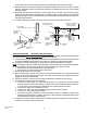
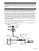
5. Connection to the power supply is provided by a 18/3 gauge x 72” long cord with grounded 3 prong plug.
6. The post purge function of the burner (fan on for 30 seconds after the call for heat) will only be enabled
when using a 24 Volt thermostat. With the line Voltage thermostat post purge operation is disabled.
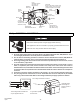
24V 2 stage thermostat connection
The two stage heater terminals must
only be supplied with 24V
72 grounded 3 prong
electrical cord
Liquid tight fitting
must be tight to
prevent ingress of
moisture
2-Stage Thermostat
43269060 rev A
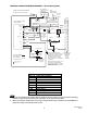
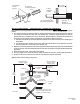
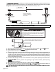
HI
C
LO
HI-LO
Adjustment Screws
(use 3/32 Hex
Allen Wrench)
1/8 NPT
Inlet Pressure
Tap with 3/16 Hex
Allen Wrench Plug
1/8NPT
Outlet Pressure
Tap with 3/16 Hex
Allen Wrench Plug
Gas Control
Knob
Wiring
Terminals (3)
Ground
Terminals (2)
OUTLET
INLET
CAUTION
Never jumper these terminals. This
shorts out valve coil and may burn
out heat anticipator in thermostat.
TWO-STAGE
GAS CONTROL VALVE
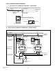
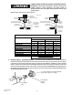
HI
LO
ON
OFF
LO
C
HI
Electric
Solenoid
Coil
Regulator
Vent Cover