INSTALLATION AND OPERATION INSTRUCTIONS OWNER / INSTALLER: For your safety this manual must be carefully and thoroughly read and understood before installing, operating or servicing this heater. INFRARED RADIANT TUBE HEATER Two Stage Push Through System (Positive Pressure) Models: PTS SERIES: (40, 50, 75, 100, 125, 150, 175, 200) – N7/L7 PTU SERIES: (40, 50, 75, 100, 125, 150, 175, 200) – N7/L7 !INSTALLER: This manual is the property of the owner.
TABLE OF CONTENTS SECTION 1.0) 2.0) 3.0) 4.0) 5.0) 6.0) 6.1) 7.0) 7.1) 8.0) 8.1) 8.2) 9.0) 10.0) 10.1) 10.2) 10.3) 11.0) 11.1) 11.2) 11.3) 12.0) 12.1) 13.0) 14.0) 15.0) 16.0) 17.0) 17.1) 18.0) 19.0) 20.0) 21.0) 22.0) 23.0) 23.1) 23.2) 23.3) 23.4) 24.0) 25.0) DESCRIPTION PAGE Safety........................................................................................................................................ Installer Responsibility.................................................................
1.0) SAFETY This heater is a self-contained two stage infrared radiant tube heater. Safety information required during installation and operation of this heater is provided in this manual and the labels on the product. The installation, service and maintenance of this heater must be performed by a contractor qualified in the installation and service of gas fired heating equipment.
Every heater shall be located with respect to building construction and other equipment so as to permit access to the heater. Each installer shall use quality installation practices when locating the heater and must give consideration to clearances to combustible materials, vehicles parked below, lights, overhead doors, storage areas with stacked materials, sprinkler heads, gas and electrical lines and any other possible obstructions or hazards. Consideration also must be given to service accessibility.
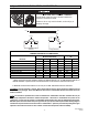
4.0) MINIMUM CLEARANCES TO COMBUSTIBLES Combustible material must be located outside the clearance dimensions listed. Failure to do so may result in death, serious injury or property damage. Minimum clearances to combustibles shall be measured from the outer surfaces as shown in the following diagram: End End Ceiling * Ceiling Front Side Below Side Rear Below 45° Angle (Maximum) Horizontal MINIMUM CLEARANCES TO COMBUSTIBLES Model No.
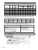
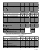
5.0) SPECIFICATIONS High Btu/hr Input Low Btu/hr Input Combustion Air Plate Part # PTS/PTU 40/25 PTS/PTU 50/30 PTS/PTU 75/50 PTS/PTU 100/65 PTS/PTU 125/80 40,000 50,000 75,000 100,000 125,000 25,000 30,000 50,000 65,000 80,000 #44140061 #44140064 #44140063 #44140062 #44140066 #32 3.5mm #21 #12 #4 PTS/PTU 150/100 PTS/PTU 175/110 PTS/PTU 200/125 150,000 100,000 175,000 110,000 200,000 125,000 #44140067 #44140067 #44140068 “A” “E” 6.9mm Model No.
BURNER PACKAGE NUMBERS: NATURAL GAS MODEL NO PTS/U 40-N7 PTS/U 50-N7 PTS/U 75-N7 PTS/U 100-N7 PTS/U 125-N7 PTS/U 150-N7 PTS/U 175-N7 PTS/U 200-N7 PROPANE GAS MODEL NO PTS/U 40-L7 PTS/U 50-L7 PTS/U 75-L7 PTS/U 100-L7 PTS/U 125-L7 PTS/U 150-L7 PTS/U 175-L7 PTS/U 200-L7 PART NO. #44149510 #44149530 #44149550 #44149570 #44149590 #44149610 #44149630 #44149650 PART NO.
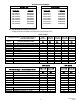
C) PTS 40-200 Series Body Package Descriptions – ALC Option (Aluminized Calorized) (Package Part Number is indicated on the outside of carton.) System Lengths 10 Ft. Pkg 20 Ft. Pkg 30 Ft. Pkg 40 Ft. Pkg 50 Ft. Pkg 44134020 44135020 44136020 44137090 44138080 PTS Body Packages – Aluminized/Aluminized or Alumi-Therm/Aluminized Part # 42912080 42912169 41932100 43319100 30462980 43318000 43980010 Each Body Package Includes: 10 Ft. Tube with 24 Hole Flange (Aluminized) 10 Ft.
Body Fastener Kit (included in body packages) 42873000 U-Bolt 02127110 Hex Nut, 5/16-18 02189020 HWHSM Screw, #10-16 x ½” TEKS 42907190 2 5 8 42907210 4 8 14 42907210 4 8 14 42907221 6 13 24 U-Bend Package U-Bend 31” Tube Support/Hanger Bracket Tube Coupling HWHSM Screw, #10-16 x ½” TEKS 43208020 1 1 1 2 43208020 1 1 1 2 43208020 1 1 1 2 43208020 1 1 1 2 42873000 43318500 30462980 02189020 60Ft.
Body Fastener Kit (included in body packages) 42873000 U-Bolt 02127110 Hex Nut, 5/16-18 02189020 HWHSM Screw, #10-16 x ½” TEKS 42873000 43318500 30462980 02189020 U-Bend Package U-Bend 31” Tube Support/Hanger Bracket Tube Coupling HWHSM Screw, #10-16 x ½” TEKS 42907190 2 5 8 42907210 4 8 14 42907210 4 8 14 42907221 6 13 24 43208020 1 1 1 2 43208020 1 1 1 2 43208020 1 1 1 2 43208020 1 1 1 2 60Ft.
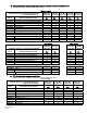
C) Corner Reflector Accessory Package, Part #43342000 (Option for PTS Series Only) 24 (61cm) Contains: Corner Reflector Assembly, #43345000……QTY–1 Speed Clips, #02266010……QTY–4 24 (61cm) 18 (46cm) D) U-Bend Package, Part #43208020 (Option for PTU Series Only) Contains: U-Bend, #42913020……QTY–1 #10-16 x ½ Self-Drilling Screws, #02189020……QTY–2 Tube Coupling, #30462980……QTY–1 31” Hanger/Tube Support, #43318500……QTY–1 E) U-Bend Reflector Package, Part #43488000 (Option for PTU Series Only) Contains: U-
7.0) TYPICAL LAYOUTS – PTU / PTS Series 10FT. SYSTEM 50 FT. SYSTEM 20 FT. SYSTEM 30 FT. SYSTEM 60 FT. SYSTEM 40 FT. SYSTEM LEGEND Burner Box 5 FT. Body Section Flue Termination 90 Deg. Elbow 10 FT. Body Section 180 Deg. U-Bend 70 FT. SYSTEM PTS 40/25 EMITTER LENGTH Min. Max. 10 Ft. 20 Ft. PTU 40/25 BODY LENGTH Min. Max. 10 Ft. 10 Ft. PTS 50/30 20 Ft 30 Ft. PTU 50/30 10 Ft. 15 Ft. PTS 75/50 20 Ft. 30 Ft. PTU 75/50 10 Ft. 15 Ft PTS 100/65 30 Ft. 40 Ft. PTU 100/65 15 Ft. 20 Ft.
above. 7.1) TYPICAL ASSEMBLY LAYOUT POISONOUS GAS AND SOOT HAZARD The heater must be assembled with the correct number of turbulator sections and tube length for the rated heat input. The turbulator must be installed in the last tube section as shown. Failure to do so may result in death, serious injury, property damage or illness from Carbon Monoxide poisoning. 10 FT. SYSTEM Stainless Steel Turbulator closest to burner PTS / U 40 only.
Form #43343530 July 08 Burner Box –13– Models: PTS 150, 175, 200 Models: PTS 125, 150, 175, 200 Models: PTS 100, 125 150 Models: PTS 50, 75, 100, 125 Models: PTS 40, 50, 75 14 (36cm) Models: PTS 40 14 (36cm) Bottom View 108 (274cm) 12 (30cm) 12 (30cm) 12 (30cm) 12 (30cm) 108 (274cm) 12 (30cm) 12 (30cm) 12 (30cm) 108 (274cm) 4 Tube Coupling (typical) 108 (274cm) 4 Tube Coupling (typical) 108 (274cm) 108 (274cm) 13 Tube Support/ Hanger Bracket 12 (30cm) Wire Han
8.1) DIMENSIONS – PTU Series Typical Dimensions Up to 50 Ft. Shown.
Form #43343530 July 08 –15– Burner Box Gasket Burner Box Suspension Chain Maximum 6 distance from burner box to the tube support/hanger bracket. 8 - 9 ¼ 8 - 10 U-Bolt Clamp & 5/16" Hex Nuts Mounting Flange 24 Hole for Aluminized Steel Tubes 6 Hole for Alumi-Therm Steel Tubes 4"OD x 10Ft. Tube See section 7 for required tubes. Typical Assembly Overview (PTS 40FT Shown) Wire Hanger Not Less Than 10 #10 Self-Drill Screws (Typical all tube supports, tube couplings and flue terminal.
Typical Assembly Overview (PTU 40FT Shown) Reflector Typical Overlap U-Bend Turbulator (See specifications section 5 for required quantities.) Tube Coupling (Typical each tube joint.) #10 Self-Drill Screws (2 each) 13 Tube Support Brk. with U-Bolt Clamp & 5/16" Hex Nuts Wire Hanger Flue Terminal Gasket Burner Box 31 Tube Support Brk. with U-Bolt Clamp & 5/16" Hex Nuts #10 Self-Drill Screws (Typical all tube supports, tube couplings and flue terminal.) 4"OD x 10Ft.
9.0) TYPICAL SUSPENSION METHODS SUSPENSION HAZARD Burner must be secured to the mounting flange with nuts. All materials used to suspend the heater must have a minimum working load of 115 lbs. All S Hooks must be crimped closed. Never use the heater to support a ladder or other access equipment. Failure to do so may result in death, serious injury or property damage. Various means of suspending the heater can be used. See the following drawings for typical examples. 1.
10.0) ASSEMBLY OF TUBE SECTIONS CUT HAZARD Sheet metal parts, particularly reflectors and vent have sharp edges. Always use gloves when handling. Failure to do so may result in death, serious injury or property damage. During field assembly of the heater body sections, the recommended procedure is as follows: 1. Before hanging heater sections, first determine the actual layout of the system (see Sections 7.0 & 8.0 for details).
10.1 ASSEMBLY OF EXTENSION SECTION MIN 8 MAX 10 BETWEEN HANGERS 1 Coupling 2 Wire Hanger 3 U-Bolt Clamp & 5/16 Hex Nuts Tube Support/ Hanger Bracket Tube Support/ Hanger Bracket 6 approx. See typical assembly overview (Section 8.0) for typical complete assembly. Assemble additional extension sections as required for all systems. (See Sections 7.0, and 8.0 for typical layout details.
4 Tube Coupling 4. 5. 6. 7. 5 Center both tubes with hole 7 #10 Self-Drilling Screws (QTY 2) 6 Slide the next tube into the coupling. Make sure both tube ends are butted together. Finish tightening both bolts to 40-60 ft.lbs. torque to ensure a complete seal. Use the two Self-drilling screws through the pre-punched holes to secure the tubes in the coupling. Band Force Bars Reaction Block Bolt Interference Pins CORRECT INSTALLATION INCORRECT INSTALLATION 8.
Turbulators MODEL 2 Ft. Turbulator Sections 4 5 5 3 7 4 0 1 PTS/U 40/25 PTS/U 50/30 PTS/U 75/50 PTS/U 100/65 PTS/U 125/80 PTS/U 150/100 PTS/U 175/110 PTS/U 200/125 10.3) ASSEMBLY HAZARD The PTS / U 40 has one stainless steel turbulator. This must be installed closest to the burner. Failure to do so may result in deterioration of the turbulator material and invalidate the warranty. ADDING REFLECTORS 1. Slide the reflectors on the tube support/hanger brackets and through the wire hangers. 2.
11.0) ADDING OPTIONAL 90º ELBOW (PTS ONLY) 1. The optional 90º elbow must be located a minimum of 10 ft. after the control box. 2. Hang the body sections in a 90º ("L") shaped pattern. Allow spacing for the elbow. The distance from one end of the elbow to the centerline of the opposite leg is 13" as shown. 3. Join the tube ends of the body sections and the elbow together and secure with tube couplings as described in Section 10.1. Tube Coupling 90 Deg.
11.2) ADDING 180°U-Bend (PTU ONLY) 1. Hang body sections parallel with each other. The centerline distance from tube at each body section should be 18” as shown. 2. Join tube ends of body sections and the U-Bend together and secure with tube couplings as described in Section 10.1. Self-Drilling Screws (QTY-2 per coupling) Tube Coupling 18 (457mm) U-Bend 11.3) ADDING OPTIONAL U-BEND REFLECTOR (PTU ONLY) 1.
12.0) ATTACHING BURNER BOX ASSEMBLY 1. Attach the burner box and gasket to end of tube flange and secure with 1/4-20 locknuts. 2. Assemble the optional end reflector flush with the end of the main body reflector. Secure by sliding speed clips onto the reflector edges. Evenly space the speed clips on the sides (one each side) and top (two required) of the reflectors to provide a snug fit. Leave a 3" space between the end reflector and the burner box assembly. 3.
12.1) CONNECTING THE TISS SYSTEM Description: The TISS (Tube Integrity Safety System) is designed to shut the main burner off in the event that a burnout occurs in the first 10ft. section of firing tube. Note: When replacing the firing tube a new TISS wire assembly PN 44176010 must also be installed. Instructions: 1. Make sure that the gap between the burner box and end of reflector is 3” and the reflector is securely attached to the reflector support bracket. Make adjustments if necessary.
3. Hold the spring retainer clamp and pull the TISS wire assembly to end of reflector at overlap joint. Slide spring retainer clamp over end of reflector as shown. Step 3 Thimble End View Spring Retainer Clamp Spring Wire & Sleeving Assembly TISS Wire Assembly PN 44176000 4. After attachment of the TISS, check to make sure that there is sufficient tension on the wire. Follow the diagram below to increase or decrease the tension as necessary. 1.
ANGLE MOUNTED HEATERS ONLY 5. If heaters are to be angle mounted, the TISS wire holder clamp must first be re-positioned as shown using the bottom hole pattern of the clamp. Follow procedures described earlier for all other adjustments. Re-position wire clamp using bottom hole pattern.
13.0) GAS CONNECTIONS AND REGULATIONS Tighten flexible gas hose and components securely. Flexible metal gas hoses must be installed without any twists or kinks in them. The hose will move during operation of the heater and it can crack if it is twisted. Failure to do so may result in death, serious injury or property damage. IMPORTANT BEFORE CONNECTING THE GAS TO THE HEATER 1. Connect to the supply tank or manifold in accordance with the latest edition of National Fuel Gas Code (ANSI Z223.
KEY DIMENSIONS AND COMPONENTS OF THE GAS CONNECTIONS Gas Pressure = 2 PSIG Gas Supply Piping Approved Flexible Connector *Manual Gas Shut Off Valve Sediment Trap (Drip Leg) 14 to 17 (36 to 43cm) 2 (5cm) Max. Displacement *Second Stage Regulator with Vent Leak Limiter to reduce the Supply Pressure below 14 W.C. * Available as Accessories Burner Movement RECOMMENDED GAS CONNECTION POSITIONS WITH 36 FLEXIBLE GAS HOSE DO NOT install gas connector vertically if fresh air is to be connected.
14.0) INSTRUCTIONS FOR PRESSURE TEST GAUGE CONNECTION Never operate the heater with the access panel open or removed. The access panels must be closed tightly with all the necessary screws during operation. Failure to do so may result in death, serious injury or property damage. The access doors on either side of the burner must be securely fastened before operating the heater. DANGER FIRE HAZARD Never operate the heater with the access panel open or removed.
HI-LO Adjustment Screws (use 3/32 Hex Allen Wrench) CAUTION Never jumper these terminals. This shorts out valve coil and may burn out heat anticipator in thermostat. Regulator Vent Cover LO Wiring Terminals (3) C Electric Solenoid Coil HI Ground Terminals (2) LO HI INLET OUTLET ON 1/8 NPT Inlet Pressure Tap with 3/16 Hex Allen Wrench Plug OFF TWO-STAGE GAS CONTROL VALVE 15.
INTERNAL CONNECTION WIRING DIAGRAM — Direct Spark Ignition Terminal Block (2-stage thermostat connections) Red Light LO C Terminal Block Plaque HI Red Red V1 Orange Black L1 Black (R) 24VAC Red V2 Blue S1 Terminal Block Plaque Fuse 2A Fusible Red Amber Lights IND Red LO C Blue NC GND HI Transformer Primary 120V Secondary 24V Green Violet Black L1 Black White L2 Black (ribbed) Black (ribbed) Blower Green P.
FIELD CONNECTION WIRING DIAGRAMS A. LOW VOLTAGE (24V) THERMOSTAT CONNECTIONS – SINGLE HEATER Receptacle Ground N Neutral L1 Hot (120V) Fused Disconnect Switch Continue To Additional Heaters Power Supply Cord (120V) HI C LO Low Fire High Fire Two-Stage Thermostat (field supplied) Burner Control Box B.
16.0) VENTING CARBON MONOXIDE HAZARD Heaters installed in an unvented mode require a minimum ventilation flow of 4 CFM per 1,000 Btu/hr of total installed capacity. In buildings with airborne contamination such as poultry houses the heater must be installed with fresh air for combustion. Failure to do so may result in death, serious injury, property damage or illness from Carbon Monoxide poisoning. A.
the flue gases, the vent pipe should be insulated and a condensation drain should be provided. 7. Minimum clearance for single-wall flue pipe to combustible material shall be 6 inches. This may be reduced when the combustible material is protected as specified in the National Fuel Gas Code or the authority having jurisdiction. 8. Single-wall metal pipe shall not originate in any unoccupied attic or concealed space and shall not pass through any attic, inside wall or concealed space, or through any floor.
#10 Self-Drill Screws (typical) 6 (15cm) minimum 4 Vent Pipe (horizontal position) 2 (5cm) Clearance Thimble 1/2 (12mm) fall per 20 ft (6m) toward vent terminal Flue Adapter Collar Vent Cap (Breidert or equivalent Type L) MULTIPLE HEATER VENTING (CONNECTIONS INTO A COMMON VENT OR MANIFOLD) Requirements for venting of multiple heaters are the same as described for SINGLE HEATER VENTING except as follows: 1.
COMMON VENTING OF MULTIPLE HEATERS IN CONFINED SPACES IS PROHIBITED. If any heater connected to a common vent system for multiple heaters is found inoperative, the heater should be disconnected from the vent system and its entrance into the vent system capped. Multiple Heater Horizontal venting arrangement.
17.0) AIR FOR COMBUSTION If indoor combustion air is to be supplied for a tightly enclosed area, one square inch of free area opening shall be provided below the heater for each 1,000 Btu/hr of heater input. Adequate clearances around the air inlet screen must be maintained at all times. In larger open areas of buildings, infiltration normally is adequate to provide air for combustion. 17.
In multiple heater applications, the combustion air intake may be ducted individually or common ducted in the same configuration as shown for venting in Section 16.0. For combustion air intake duct sizing, please refer to the Vent Sizing Table and use the diameter indicated, based on the number of heaters per duct. SIDE VIEW (straight configuration) Flue vent termination must be 1 ft. (30 cm) higher than combustion air inlet cap. Combustion Air Intake 18.
19.0) SEQUENCE OF OPERATION The chart below shows the sequence of operation for the normal operating cycle of the PTS/PTU when connected to a permanent 120V power supply and the heater is turned on and off by a remote 24V thermostat. (Electrical connection diagram B).
20.0) BURNER COMPONENT LOCATIONS 2 6 30 32 31 9 7 12 8 33 Note: This panel must remain closed for burner operation. 3 4 10 3 11 5 Note: This panel must remain closed for burner operation.
21.0) CLEANING AND MAINTENANCE ELECTRIC SHOCK & EXPLOSION HAZARD Disconnect electrical power and gas supply before servicing. Failure to do so may result in death or serious injury. This heater must be cleaned and serviced annually by a qualified contractor before the start of each heating season and at any time excessive accumulation of dust and dirt is observed. Maximum heating efficiency and clean combustion will be maintained by keeping the heater clean.
Form #43343530 July 08 –43– Yes Troubleshooting continued on the next page. Yes Does the low fire amber light come on? Yes Does the blower stay on? No Check line voltage circuit. Repair fault. Replace ignition module. Yes Is the LED on the ignition module No steady ON? No Check NO terminal of the air switch connection. Replace red light. No if fuse carrier is tight and the fuse has no continuity, replace the fuse. No Check terminals for continuity at transformer.
–44– Form #43343530 JJuly 08 Troubleshooting continued on the next page. Yes Repair terminal connections. No Check terminal connections to the gas valve, are they tight? Repair terminal connections. Restart troubleshooting. No No Turn on the gas valve? No Check external thermostat wiring and thermostat set point. No Correct grounding problem. No Adjust terminal connection. Restart troubleshooting. No Repair or replace flame sense electrode. No No Repair terminal connections.
Form #43343530 July 08 –45– Yes Purge the gas supply lines. No Replace ignition module. Yes Is the LED on the Has all the air been ignition module purged from the gas supply lines? Yes steady on? Troubleshooting continued from previous page Adjust manifold gas pressure. No Check electrode spark gap. Is it 1/8? No Adjust manifold pressure. Restart troubleshooting. No Remove blockage. Restart troubleshooting. Contact factory for assistance. No Replace blower assembly.
23.0) REPLACING PARTS ELECTRIC SHOCK & EXPLOSION HAZARD Disconnect electrical power and gas supply before servicing. Failure to do so may result in death or serious injury. Only use genuine Space-Ray replacement parts. Parts are available from the factory for replacement by a licensed person. Refer to the Replacement Parts Guide in Section 25 for all replacement parts. 23.
23.2) REMOVAL OF GAS VALVE AND MANIFOLD ASSEMBLY Step 1 Step 3 23.3) Open hinged access panel and disconnect wires from gas valve. Step 4 Loosen screws from manifold clamp and burner assembly. Remove (6) screws from end panel. Rotate gas valve and manifold assembly slightly counter-clockwise and slide out from housing. AIR SWITCH PRESSURE CHECK Connector Tees Air Switch P2 - Step 2 Remove side access panel. P1 + P1 + Temporary 1/4 ID Silicone / plastic tubing for pressure test. P2 - + 0.
3. Connect plastic tubing of a digital or inclined water manometer with a 0-2” scale onto the connector tees. 4. Turn heater on and wait until blower motor is activated. 5. Observe air pressure from manometer. This should be higher than the set point indicated below for correct operation. Model Operating Pressure Model PTS/U 40/25 0.98” W.C. Hot PTS/U 125/80 PTS/U 50/30 0.98” W.C. Hot PTS/U 150/100 PTS/U 75/50 0.70” W.C. Hot PTS/U 175/110 PTS/U 100/65 0.70” W.C.
24.0) INSTALLATION DATA Date of Installation: # of Heaters in System: Serial No. N = Natural Gas L = Propane Gas Model: PTS or PTU 25.0 REPLACEMENT PARTS GUIDE – BURNER BOX Item No. Part No.
29 30 31 32 33 34 35 36 37 38 38a 39 40 40a 41 41a 42 42a 43 44 45 46 47 48 48a 48b 42744079 42744069 30635030 03988100 03988100 43563040 42709000 42395010 03946010 42752250 30504040 30701240 44145060 03333140 30333250 30333260 Air Sensing Tube Asm. (straight) 1/4"od Air Sensing Tube Asm.
22 (W)TH P.
BODY COMPONENTS ITEM PART NO. 1 02266010 2 43980010 3 42873000 3a 02127110 4 43318000 5 43319050 6 43319100 7 43320000 8 43342000 9 42921000 10* 44028170 10a** 44028030 11 44028100 11a 44028060 12 44028120 12a 44028010 13 43208010 14 02189020 15 30462980 16 43208020 17 43488000 18 30504500 19 44152240 DESCRIPTION Reflector Speed Clip Wire Hanger “U” Bolt Clamp, 4” OD Tube 5/16-18 Hex Nut (2 per “U” Bolt) Tube Support/Hanger Bracket, 13” Reflector, 4’-11½” long (5’ section only; 1 per 5 ft.