
- Gas Fired Products Inc. Infrared Gas Heater Installation and Operation Instructions

Form #43343530
–12– JJuly 08
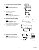
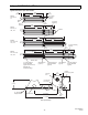
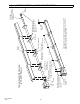
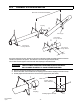
60 FT. SYSTEM
50 FT. SYSTEM
20 FT. SYSTEM
30 FT. SYSTEM
40 FT. SYSTEM
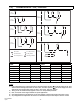
LEGEND
Burner Box 10ft Aluminized Tube 24
Hole Flange
or
10ft Alumi-Therm Tube
6 Hole Flange
Coupling 10ft Aluminized or HRS
Tube model dependent
2ft Aluminized
Steel
Turbulator
sections
70 FT. SYSTEM
10 FT. SYSTEM
2ft Stainless
Steel
Turbulator
sections
Stainless Steel Turbulator
closest to burner PTS / U
40 only.
above.
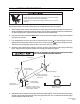
7.1) TYPICAL ASSEMBLY LAYOUT
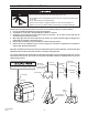
Failure to do so may result in death, serious injury, property damage or illness
from Carbon Monoxide poisoning.
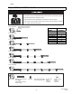
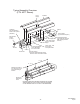
The heater must be assembled with the correct number of turbulator sections
and tube length for the rated heat input.
The turbulator must be installed in the last tube section as shown.
POISONOUS GAS AND SOOT HAZARD
MODEL
2 Ft. Turbulator
Sections
PTS/U 40/25
4
PTS/U 50/30
5
PTS/U 75/50
5
PTS/U 100/65
3
PTS/U 125/80
7
PTS/U 150/100
4
PTS/U 175/110
0
PTS/U 200/125
1