
- Gas Fired Products Inc. Infrared Gas Heater Installation and Operation Instructions

Form #43343530
July 08 –15–
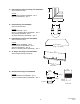
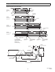
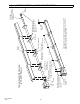
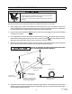
8.2) HEATER ASSEMBLY / JOINING OF TUBE SECTIONS
Typical Assembly Overview
(PTS 40FT Shown)
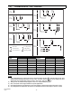
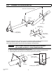
4"OD x 10Ft.
Tube
See section
7
for required tubes.
Tube Support Bracket
U-Bolt Clamp &
5/16" Hex Nuts
Mounting
Flange
24 Hole for Aluminized Steel Tubes
6 Hole for Alumi-Therm Steel Tubes
Wire Hanger
Gasket
Burner
Box
Flue
Termin
a
5 hanging points to be used for suspension for a typical 40ft
long system. There must be two hanging points on the first
tube and one on each of the other tubes
Maximum 6 distance
from burner box to the
tube support/hanger
bracket.
8 - 9 ¼
8 - 10
8 - 10
Not Less
Than 10
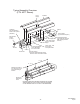
#10 Self-Drill Screws
(Typical all tube supports,
tube couplings and flue
terminal.)
Typical
Overlap
Turbulator
(See specifications
section 5 for required
quantities.)
Tube Coupling
(Typical each tube joint
.
)
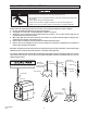
Burner Box
Suspension
Chain