
- Gas Fired Products Inc. Infrared Gas Heater Installation and Operation Instructions

Form #43343530
July 08 –41–
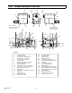
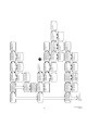
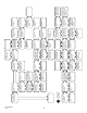
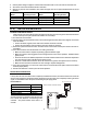
20.0) BURNER COMPONENT LOCATIONS
Legend
:
1 Cabinet Assembly
2 Access Panel - Top
3 Access Panel - Hinged (2 ea)
4 Access Panel - LH Burner
5 Access Panel - RH Burner
6 Air Inlet Screen
7 Gas Inlet Connection - 1/2NPT
8 Power Supply Cord - 120V
9 Burner Sight Glass
10 Indicator Light - Amber (Gas Valve)
11 Indicator Light - Red (Air Switch)
12 Tube Flange Connection
13 Main Burner
14 Flame Screen (200m/BTU units only)
15 Electrode
16 Flame Sensor
17 Main Burner Orifice
18 Air Restrictor Plate
2
9
4
3
6
7
8
10
11
5
12
25
Note: This panel
must remain closed
for burner operation.
Note: This panel
must remain closed
for burner operation.
30
3
32
24
1
26
27
28
29
35
14
15
16
13
17
18
19
22
23
20
33
21
34
31
19 Gas Control Valve
20 Ignition Module
21 Ignition Cable
22 Blower Assembly
23 Transformer - 120/24 VAC
24 Terminal Block/Fishpaper Shield
25 Air Switch
26 Air Sensing Tube (P1+)
27 Air Sensing Tube (P2-)
28 Manifold Pipe
29 Manifold Support Bracket/Clamp
30 Terminal Block (24V thermostat)
31 Terminal Block (TISS connection)
32 Starting Collar
33 Valve Holder Plate
34 Fuseholder/Fuse (2 amp)
35 Combustion Air Plate