
User Manual


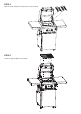

1514
NATURAL GAS CONVERSION
TO BE INSTALLED ONLY ON OR IN A NON-
COMBUSTIBLE ENCLOSURE
Note: Recommended clearances must be maintained.
Tools Required:
Thin (2.5mm diameter) flat Screw Driver, Adjustable
spanner, Phillips head screw driver.
GAS PIPING
1. (a) A minimum pipe diameter of 15mm is required for inlet
piping. A lever operated shut-off valve should be
installed within 1 metre of the appliance for servicing
the unit.
(b) Where it is not practical to install solid tube AGA
certified to AS/NZS 1869 class A stainless steel
braided hose can be installed. This hose assembly
must comply with AS5601 Gas Installations, pipe
sizing tables and shall not exceed 3 metres in
length. The internal diameter of the hose must not
be less than 10mm.
2. Check with local and state plumbing and heating
codes regarding sizing of the gas lines.
3. All gas pipe connections must be sealed with a gas
pipe compound resistant to Natural Gas.
4. Installation of a drip leg if required in the gas supply
line must conform to AS5601.
5. When checking for gas leaks, do not use an open
flame. Use a soap and water solution and check for
bubbles indicating gas leakage.
6. Installation of 1/8” NPT plugged tapping, accessible for
test gauge connections, is required upstream of the gas
supply connection.
Warning
Improper installation, adjustment, alteration, service or
maintenance can cause injury or property damage. Read
the instructions thoroughly before installing or servicing
this equipment.
SERVICING INSTRUCTIONS
Appliances should be serviced at least annually and
servicing must only be carried out by a Licensed Plumber
or Authorised Person.
Clean the Burner Ports and top with a Soft Brush.
Inspect and clean all combustion air inlets, then replace
the Burner ensuring it is firmly secured.
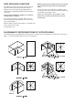
Minimum Clearance for Ventilation:
Rear 600 mm Side 600 mm
Conversion ONLY to be done by an authorised person.
NOTE TO THE INSTALLER
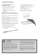
1. The injector size is increased by removing the
Propane Nozzle (outer brass cap) and leaving the
Natural Gas Nozzle in place. Ensure the Natural gas
nozzle is still tight and in correct position; and the
hole size is correct. Main burners is 1.5mm, rear
burner is 1.59mm.
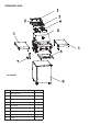
2. The gas valve plug by-pass orifices must be
increased. This is done by removing the control knob
from the front of the valve spindle; insert thin flat
recess screwdriver into the end of the spindle, locate
the screw end and turn the screw a ¼ turn Clockwise.
Air for combustion is provided by openings in the
side and bottom of the combustion chamber.
TEST OPERATION OF APPLIANCE BEFORE LEAVING.
WARNINGS
• Improper installation, adjustment, alteration, service or maintenance can cause injury
or property damage.
• Read the instructions thoroughly before installing or servicing this equipment.
• THIS APPLIANCE MUST NOT BE INSTALLED OR USED INDOORS.
• NATURAL GAS APPLIANCE. TO BE INSTALLED ONLY BY AN AUTHORISED PERSON.
• THE AUTHORISED PERSON WILL PROVIDE A CERTIFICATE OF COMPLIANCE.
• A suitable AGA approved natural gas pressure regulator must be installed in the pipeline and be set at 1 kPa.