GALAXY BBQ & MODULES 1 DOOR FRIDGE TOP Model No. BQ1094 2 DOOR FRIDGE TOP Model No. BQ1095 6 BURNER BBQ Model No. BQ1090, BQ1090NG, BQ1090BL, BQ1090BLNG DRAWER MODULE Model No. BQ1093, BQ1093BL BUILT IN BBQ Model No. BQ1090B, BQ1090BNG, BQ1090BLB, BQ1090BLBNG STORAGE MODULE Model No. BQ1092, BQ1092BL SINK MODULE Model No. BQ1091, BQ1091BL Important: Retain these instructions for future use. Gasmate® is a registered trademark of Sitro Group Australia Pty Ltd www.gasmate.com.au Aber Living, N.Z. www.
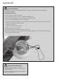
READ ME FIRST GAS LEAK TESTING It is important that you leak test the BBQ before first use and every time the gas cylinder is refilled and reconnected to the BBQ. To Complete Leak Test • Make sure all the control knobs are OFF. • In a small container, mix up a solution of water and detergent/soap. • Mix the solution well (about the same concentrate as washing up water). • Turn the cylinder ON by rotating the knob anti-clockwise.
GENERAL INFORMATION FOR YOUR SAFETY • Never test for gas leaks with a lit match or open flame. Never light barbecue with hood closed or before checking to ensure the burner tubes are fully seated over gas valve orifices. Failure to comply with these instructions could result in a fire or explosion which could cause serious bodily injury, death or property damage. • Never lean over cooking surface when lighting. CAUTION: Accessible parts may be very hot.
GENERAL INFORMATION Hose & Regulator Safety The regulator and hose assembly supplied with the barbecue are suitable for Propane Gas. IMPORTANT Read these instruction carefully prior to use. Familiarise yourself with the appliance before connecting it to it’s gas container. Keep these instructions for future reference. A gas regulator adjusted to have an outlet pressure of 2.75kPa is supplied for connection to the propane gas cylinder.
ELECTRICAL INFORMATION To reduce the risk of personal injury or damage to property, follow basic safety precautions when using this product, including the following: IMPORTANT SAFEGUARDS READ THESE INSTRUCTIONS CAREFULLY BEFORE USING THE PRODUCT. KEEP THE INSTRUCTIONS HANDY FOR FUTURE REFERENCE. • Important: Always operate the Product from a power source of the same Voltage, Frequency and Rating as indicated on the Product Identification Plate.
ELECTRICAL DATA GENERAL ASSEMBLY IMPORTANT CONNECTING & DISCONNECTING TO THE GAS SOURCE This product is fitted with a sealed electrical connection plug that is compatible with the product, the mains supply for Australia and meets the requirements of international standards. This product must be connected to a supply voltage that is equal to that stated on the rating label.
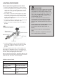
LIGHTING PROCEDURE Burner Operation & Ignition System Check 1. Turn the control knobs clockwise to “OFF” position. 2. Connect the regulator to the gas bottle. Turn the gas supply “ON” at the cylinder. Check with the use of soapy water for any gas leakage between the bottle and the regulator 3. Push down a control knob and keep pressing whilst turning anti-clockwise to the “HIGH” position whilst also pressing the ignition button (a clicking sound is heard), this will light the burner.
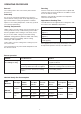
OPERATING PROCEDURE Burn-off Roasting The cooking surface does not need any burn-off time after first use. For best results when roasting remove the hotplate and centre the grill. The outer two burners should be used on the low to medium setting. Preheating Adjust the control knob to maintain the temperature around the medium mark. It is necessary to preheat the barbecue for at least 5 minutes before cooking certain foods, depending on the type of food and the cooking temperature.
CARE & MAINTENANCE Location of your Barbecue As with all appliances, proper care and maintenance will keep them in top operating condition and prolong their life. Your new gas barbecue is no exception. By following these cleaning procedures on a timely basis, your barbecue will be kept clean and working properly with minimum effort. DO NOT use your barbecue in garages, porches, sheds, breezeways, or other enclosed areas. Your barbecue is to be used OUTDOORS.
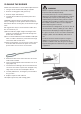
CLEANING THE BURNER Follow these instructions to clean and/or replace burners. WARNING 1. Turn gas off at control knobs and gas cylinder. Beware of spiders and wasps. Burner tube should be inspected and cleaned periodically. 2. Remove cooking grates and grease tray. 3. Remove clip at end of burner. To avoid any flare-ups, it is recommended that the drip tray be checked and emptied regularly. Contents of the drip tray may be very hot during cooking.
EXPANDED VIEW - BQ1090, BQ1090BL Key Description Quantity Key Description Quantity 1 Main body 1 2 Flame tamer 6 3 Warming rack 1 4 Cooking plate 1 5 Cooking grid 2 8 Trolley right panel 1 7 Fat tray 1 10 Trolley rear panel 1 9 Right door 1 12 Trolley bottom panel 1 Trolley right inner panel 1 11 Trolley top panel 1 14 13 Gas bottle holder 1 16 Drawer 2 15 Trolley left inner panel 1 17 Shelf inside cabinet 1 17 Shelf inside cabinet 1 18 Left door 1
ASSEMBLY INSTRUCTIONS IMPORTANT: Remove any transit protection material before use. Tools required: 3. Unscrew ignition cap and place a Battery (Size: AA) into place with the (+) end facing outwards. Screw cap back on. Upon pressing the ignition button, you should hear a clicking sound. STEP 1 Unscrew ignition cap and place a Battery (size AA) into place with the (+) end facing outwards. Screw cap back on. Upon pressing the ignition button, you should hear a clicking sound. 4.
EXPANDED VIEW - BQ1090B, BQ1090BLB 4 11 7 8 1 6 7 2 8 9 10 Key Description Quantity Key Description Quantity 1 Main body 1 2 Flame tamer 6 3 Warming rack 1 4 Cooking plate 1 5 Cooking grid 2 6 Side burner grid 1 7 Side bracket 2 8 Fat tray 1 9 Transformer 1 10 Adjustable feet 4 13
ASSEMBLY INSTRUCTIONS STEP 1 Assemble the side bracket or adjustable feet.
BUILT-IN BBQ DIMENSIONS 770mm MINIMUM 150mm MINIMUM 1488 (BQ1090B) GAS CYLINDER NOT TO BE INSTALLED UNDERNEATH NOTE: TO BE INSTALLED BY AN AUTHORISED PERSON. PLEASE NOTE: MINIMUM CLEARANCE TO COMBUSTIBLES UNDER FAT TRAY IS 150mm. THE MATERIAL FOR THE CABINET (ISLAND) MUST NOT BE COMBUSTIBLE.
NATURAL GAS CONVERSION Conversion ONLY to be done by an authorised person. TO BE INSTALLED ONLY ON OR IN A NON-COMBUSTIBLE ENCLOSURE SERVICING INSTRUCTIONS Appliances should be serviced at least annually and servicing must only be carried out by a Licensed Plumber or Authorised Person. Note: Recommended clearances must be maintained. Tools Required: 7mm Drill, Thin (2.5mm diameter) flat Screw Driver, Adjustable spanner, Phillips head screw driver. Clean the Burner Ports and top with a Soft Brush.
SAFE APPLIANCE LOCATIONS This appliance shall only be used in an above ground open-air situation with natural ventilation, without stagnant areas, where gas leakage and products of combustion are rapidly dispersed by wind and natural convection. Any enclosure in which the appliance is used shall comply with the following: An enclosure with walls on all sides, but at least one permanent opening at ground level and no overhead cover.
ASSEMBLY INSTRUCTIONS Tools Required Standard Phillips-head screw driver. IMPORTANT To join your kitchen together use 2 wing screws and nuts as shown. Remove all packing and transit protection before assembly. CAUTION: Ensure no packing material is left in BBQ before lighting.
SINK MODULE - BQ1091, BQ1091BL The sink module is flexible, follow the below steps to interchange it.
SINK MODULE - BQ1091, BQ1091BL Add the shelves (total 3pcs) into the cabinet locating the rear pins through the back panel and securing with the clips then loosen the screws at each of the front corners (see diagram below). Finally secure by tightening the screws. Insert the tap thread through the hole in the top and secure with the nut from underneath, inside the cabinet. See diagram below. Fittings required will depend on the situation and location of the BBQ; contact your local hardware store.
STORAGE MODULE - BQ1092, BQ1092BL Add the shelves (total 6pcs) into the cabinet in the same way as for the Sink Module (see BQ1091).
90 DEGREE CORNER MODULE - BQ1027 (Square corner, infill panel, 14 x M6 Screws, 6 x M6 nuts.) Attach the Infill panel to the inside of the 90 degree corner and fix with 2 screws as shown. Attach the corner module to the side of 2 Modules or a Module and BBQ, with 4 screws into the nutserts included in the module or BBQ side panels. Fix the infill panel at the base with a screw and nut to each module.
TOP FOR 2 DOOR BAR FRIDGE - BQ1095 Rest the Frame top onto the fridge, with the front fascia overhanging at the front. Push the frame backwards until the front of the frame catches under the front of the fridge. Attach the brackets to the underside of the frame using the screws provided (as shown below). And tighten the thumb screws until the rubber stops push against the back of the fridge locking the frame into place.
For any queries or assistance call Customer Service (Australia Only) 1300 174 876 Hours of operation: Monday to Friday 8am - 5pm EST Do not return to place of purchase. Keep your purchase receipt, this will be required to make any claims under the 12 month warranty.