
Install Instructions


GASTITE DIVISION, TITEFLEX CORPORATION / 1116 Vaughn Parkway / Portland, TN 37148
800.662.0208 / www.gastite.com / gastite@gastite.com
19
SECTION 3: SYSTEM CONFIGURATION / JANUARY 2019
3.1.5 ALLOWABLE PRESSURE DROP
With respect to gas pipe sizing, the intent of all model codes is to ensure that there is sufficient gas volume and pressure
supplied to the appliance for proper operation. Language from the International Fuel Gas Code clearly illustrates this point.
“Allowable Pressure Drop: e design pressure loss on any piping system under maximum probable flow
conditions, from point of delivery to the inlet connection of the equipment, shall be such that the supply
pressure at the equipment is greater than the minimum pressure required for proper equipment operation.”
e FlashShield™ low-pressure tables are intended for use at a system pressure of 1/2 PSI or less, which encompasses the range
of commonly delivered utility pressures and equipment requirements. To determine which table to use determine the system’s
allowable pressure drop. e appropriate pressure drop can be calculated by subtracting the appliance inlet pressure (typically
5"WC for NG, 10.5"WC for LPG) from the gas source pressure (gas meter for NG, secondary regulator for LPG). Use the
FlashShield™ capacity table labeled with the appropriate allowable pressure drop and gas type. Increasing the available pressure
drop will increase the available BTUHs, thus decreasing pipe sizes. It is advantageous to allow for a larger pressure drop.
e Summation Method of pipe sizing calculates the actual pressure loss through each section of pipe. e sum of all the
losses is subtracted from the starting supply pressure to determine the inlet pressure to each appliance. e appliance inlet
pressure must fall within the manufacturer’s range for proper operation.
Note: Regardless of sizing method employed, the typical NG system should be sized for a minimum appliance inlet
pressure of 5"WC and 10.5"WC for LPG system. Pressures less than the typical minimums may be sufficient for proper
appliance operation but should be reviewed with the manufacturers’ input rating and the local administering authority.
Conversely, some modern higher performance appliances require an inlet pressure greater than the typical minimums.
Check the manufacturers’ input rating before sizing.
3.1.6 SIZING METHODS
Capacity Tables from this Guide (Section 7) or appropriate code approved tables must be used when sizing FlashShield™
CSST. e sizing tables used in this manual include losses for four 90-degree bends, and two end fittings. Tubing runs with
larger numbers of bends and/or fittings should be increased by an equivalent length of tubing to the following equation: L
= 1.3 (N): where “L” is additional length of tubing, and “N” is the number of additional fittings, or 90 degree bends.
FlashShield™’s Longest Run tables and Summation tables are produced from the same fluid flow equations. As such, they
will provide the same results taking into account any rounding of distance or capacity. ese fluid equations come from
data produced by a third party laboratory. e testing was performed on actual FlashShield™ CSST while tables in the code
reflect the most restrictive CSST.
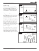
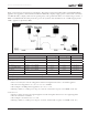
THE LONGEST RUN METHOD:
A modified version of the longest run (commonly used in conventional rigid pipe systems) is presented here and used in
Examples 1, 2 & 3. is method may be used for any pressure as listed in the appropriate Capacity Table.
For sizing each length of pipe, determine the total gas load for all appliances serviced by that section and the maximum
distance over which that particular section delivers gas. e maximum distance includes overall length from the meter to
the furthest appliance serviced by that run. Refer to Section 7 Capacity Tables for the maximum flow capacity of CSST at
the required piping length.
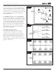
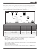
For sizing dual-pressure systems, the piping from the meter to the pounds-to-inches regulator is sized separately from the
piping downstream of the regulator outlet. is procedure is shown in Examples 4 & 5.