
Installation Guide

Install interior cover (G).Install four AA alkaline batteries
(not included).
Enter default Master Code 123456 and
the lock will set up bolt direction to
complete installation.
AA
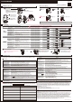
INSTALLING THE LATCH
Turn to extend the latch bolt.
Backset
2-3/4 should be visible.
Hardware Used
3/4 in. (19 mm) Wood Screw Qty. 2
A. Deadbolt Latch Adjustment (
SKIP THIS if your door has a 2-3/8 in. (60 mm) backset)
B. Install latch (H). Insert screws and tighten.
a. Hold latch back and twist
outward.
b. Pull backward to the end.
a. Then twist inward to x at 2-3/4 in.
(70mm) backset.
b. Turn back to retract the latch bolt.
L
L
INSTALLING THE LOCK ASSEMBLIES
Hardware Used
1-13/16 in. (46 mm) Mounting Bolt Qty. 2
Insert screws and tighten.
M
M
TEMPLATE
1-3/4 in.
(45 mm)
2 in.
(51 mm)
1-3/8 in.
(35 mm)
1-9/16 in.
(40 mm)
Backset 2-3/8 in. (60 mm)
Backset 2-3/4 in. (70 mm)
Fold here
Place on door edge
NOTE: Double check your product for the correct hole sizes.
Drill 1 in. (25 mm) hole at center of
door edge.
WARNING :
If the door needs to be drilled, please be familiar with how to use a drill safely and understand all of the door preparation steps before proceeding.
CAUTION :
Please use four alkaline batteries (not included) for the best performance.
CAUTION :
Use alkaline batteries for better performance.
Be sure to insert them correctly by matching the + and – polarity markings.
Do not mix old batteries and new batteries or standard (carbon-zinc) with alkaline batteries.
The following instructions should be followed to properly protect and maintain your lockset:
A. Remove locks, or do not install locks, prior to painting your door.
B. Periodically clean with mild soap and a soft cloth only.
C. Do not use any abrasives or chemical products containing alcohol, benzene, or acids, and avoid using sharp or abrasive objects to clean this lockset.
D. Do not allow any water or liquids into the lockset during installation.
A. Do not attempt to disassemble any internal components of the lockset. Doing so will void the limited warranty.
B. Do not drop or hit the lockset. Too much shock may result in permanent damage.
C. Do not use pins or sharp objects to press the keypad.
D. Always create a backup of information you wish to keep (Master Code, user code, etc.) Please use the last page of this booklet as a reference.
E. Promptly change the Master Code before operating this lockset.
A. Before beginning installation of product, make sure all parts are present. Compare parts with package contents list and hardware contents list.
If any part is missing or damaged, do not attempt to assemble, install or operate the product.
B. Make sure backset of lock is same as backset of your door. If an adjustable latch is to be used, please adjust the backset to t your door.
C. Please read these instructions completely before attempting to install lock.
Tools Required for Assembly (not included): Phillips screwdriver
Helpful Tools (not included):
Prepare the door jamb: Use the strike plate as a template to drill the latch and screw holes and chisel out the mortise.
The strike plate must fit flush with the surface of the door jamb.
Cut out TEMPLATE and use to mark the door, drill holes, and chisel out the mortise.
Backset
Centerline
Outline
Faceplate
NOTE :
If replacing an existing lock or installing in a pre-drilled door, please skip to INSTALLATION INSTRUCTIONS.
Use TEMPLATE to measure your hole size and backset.
NOTE :
Drill from both sides of the door to prevent wood splitting.
ITEM #0788482
ELECTRONIC KEYPAD DEADBOLT
MODEL #GCX2D01
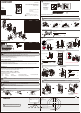
PACKAGE CONTENTS
Read the precautions and instructions in this manual before installing and using this lock. Save this manual for future reference.
HARDWARE CONTENTS
SAFETY INFORMATION
INSTALLATION INSTRUCTIONS
CARE AND MAINTENANCE
PREPARATION
DOOR PREPARATION
F Interior Assembly
A Exterior Assembly
B Power Strip
C Torque Blade
E Mounting Plate
D Exterior Gasket
1
1
1
1
1
1
PART
DESCRIPTION
QUANTITY
K Dust Box
G Interior Cover
H Latch
I Key
J Strike Plate
1
1
2
1
1
1 in. (25 mm)
2-1/8 in. (54 mm)
2-1/8 in. (54 mm)
Chisel 13/64 in. (5 mm) deep.
GCD-KPDDW12 Rev. 16/03-00
https://goo.gl/ENGLFG
ATTACH YOUR RECEIPT HERE
Serial Number _______________
Purchase Date_______________
Call customer service at 1-877-442-8347,
8:00 a.m. - 8:00 p.m., EST, Monday - Friday.
Questions?
L 3/4 in. (19 mm) Wood Screw
M 1-13/16 in. (46 mm) Mounting Bolt
N 13/16 in. (20 mm) Screw
2
2
1
PART
DESCRIPTION
QUANTITY
O 5/16 in. (8 mm) Screw
2
2
P 2 in. (51 mm) Strike Screw
CAUTION:
Be sure the latch cam is upright before making any backset adjustment.
Remove the interior cover (G)
from the interior assembly (F).
Hardware Used
Install interior assembly (F).
Insert screws and tighten.
5/16 in. (8 mm) Screw Qty. 2
13/16 in. (20 mm) Screw Qty. 1
Note: The metal connector side should face outward.
Connect the cable rmly
into connector port.
N
O
N
The cable must be arranged as shown in the diagram.
Scan for
Installation
Ø 2-1/8 in. (54 mm)
H
L
C
I
E
F
M
O
N
G
B
A
D
P
J
K
N
O
P
M
L
Strike slot dimension:
d. 5/32 in. (4 mm)
e. 2-3/4 in. (70 mm)
f. 1-1/8 in. (28 mm)
Hardware Used
NOTE: The dust box (K) is optional.
2 in. (51 mm) Strike Screw Qty. 2
b. 1-9/16 in. (40 mm)
a. 1-3/16 in. (30 mm)
c. 1 in. (25 mm)
Door jamb hole dimension:
P
K J P
c
f
a
d
b
e
The bulged part of the mounting
plate must face towards the door.
Thread the cable through the
hole and under the latch.
Insert the blade.
O
• Pencil
• Chisel • Tape Measure
• Hammer • 2-1/8 in. (54 mm) Hole Boring Bit
• 1 in. (25 mm) and 1/8 in. (3 mm) Drill Bits
• 2 in. (51 mm) 6d Common Nail• Power Drill
• Flathead Screwdriver
ESTIMATED ASSEMBLY TIME: 40 - 60 MINUTES
H
A
A
E
G
G
F
F
G
Slide the cable through the
notch in mounting plate.
E
B