GATEWAY NOTEBOOK SERVICEGUIDE ®
Contents Replacing Notebook Components . . . . . . . . . . . . . . . . . . . . . . . . . . . . . . . . . . . 1 Identifying the notebook model . . . . . . . . . . . . . . . . . . . . . . . . . . . . . . . . . . . . . . . . 2 Identifying components . . . . . . . . . . . . . . . . . . . . . . . . . . . . . . . . . . . . . . . . . . . . . . 3 Preparing your work space . . . . . . . . . . . . . . . . . . . . . . . . . . . . . . . . . . . . . . . . . . . 4 Preventing static electricity discharge . . . . . . . . .
Contents ii
Replacing Notebook Components • • • • • • • • • • • • • • • • • • • • • • • • Identifying the notebook model Identifying components Preparing your work space Preventing static electricity discharge Preparing the notebook Adding or replacing memory modules Replacing the DVD drive Replacing the cooling assembly Replacing the processor Replacing the IEEE 802.
Replacing Notebook Components Important The photographs in this guide may vary in appearance from the notebook. These variations may include color and finishing of the case and the shape of the touchpad. Important This service guide is not intended to be provided to individual users or consumers. It cannot be provided to anyone other than an authorized service provider.
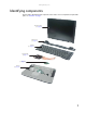
www.gateway.com Identifying components Use this chart to identify the main components of the notebook. For a complete list of replaceable parts, see “Contents” on page i.
Replacing Notebook Components Preparing your work space Before performing maintenance on the notebook, make sure that your work space and the notebook are correctly prepared. • Wear a grounding (ESD) wrist strap, and use a grounded or dissipative work mat. • Use a stable and strong table, and make sure that the table top is large enough to hold each component as you remove it. • Use bright lighting to make part identification easier.
www.gateway.com Preventing static electricity discharge Warning To avoid exposure to dangerous electrical voltages and moving parts, turn off the notebook, remove the battery, and unplug the power cord, modem cable, and network cable before opening the case. Warning To prevent risk of electric shock, do not insert any object into the vent holes of the notebook. Important Before performing maintenance on the notebook, you should read and understand the information in this section.
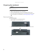
Replacing Notebook Components Preparing the notebook Warning To avoid exposure to dangerous electrical voltages and moving parts, turn off the notebook, remove the battery, and unplug the power cord, modem cable, and network cable before opening the case. Replace the cover before you restore power or reconnect the modem and network cables. To prepare the notebook for maintenance: Make sure that the DVD drive does not contain a disc.
www.gateway.com Adding or replacing memory modules Important Use only memory modules designed for this Gateway notebook. Tools you need to complete this task: Phillips #0 screwdriver Screws removed during this task: 1 black (keyboard) Memory bay To add or replace memory modules: 1 Complete the steps in “Preparing the notebook” on page 6.
Replacing Notebook Components 2 Remove the keyboard screw. Tip The screw hole is marked with a K. Keyboard screw 3 Loosen the six memory bay cover screws (these screws cannot be removed). Tip Depending on your model, not all screws may be captive.
www.gateway.com 4 Use the thumb notch to lift the memory bay cover, then remove it. Be careful not to break off the tabs located on the end of the cover opposite of the thumb notch. Thumb notch 5 If you are removing a module, gently press outward on the clip at each end of the memory module until the module tilts up.
Replacing Notebook Components 6 Pull the memory module out of the slot. 7 Hold the new or replacement module at a 30-degree angle and press it into the empty memory slot. This module is keyed so it can only be inserted in one direction. If the module does not fit, make sure that the notch in the module lines up with the tab in the memory bay. 8 Replace the memory bay cover, then tighten the cover screws. 9 Replace the keyboard screw. Tip The screw hole is marked with a K.
www.gateway.com Replacing the DVD drive Tools you need to complete this task: Phillips #0 screwdriver Screws removed during this task: 1 black (keyboard) 1 black (DVD drive) To replace the DVD drive: 1 Complete the steps in “Preparing the notebook” on page 6. 2 Remove the keyboard screw. Tip The screw hole is marked with a K.
Replacing Notebook Components 3 Loosen the six memory bay cover screws (these screws cannot be removed). Tip Depending on your model, not all screws may be captive. Screws Screws 4 Use the thumb notch to lift the memory bay cover, then remove it. Be careful not to break off the tabs located on the end of the cover opposite of the thumb notch.
www.gateway.com 5 Remove the DVD drive screw. Screw 6 Slide the DVD drive out of the drive bay by pushing on the DVD bracket. DVD bracket 7 8 9 10 Slide the new DVD drive into the drive bay. Make sure that the drive fits securely in the bay. Secure the DVD drive with the screw removed in Step 5. Replace the memory bay cover, then tighten the cover screws. Replace the keyboard screw. Tip The screw hole is marked with a K.
Replacing Notebook Components Replacing the cooling assembly Tools you need to complete this task: Phillips #0 screwdriver Additional materials you may need to complete this task: • X-23-7762 thermal grease Screws removed during this task: 1 black (keyboard) To replace the cooling assembly: 1 Complete the steps in “Preparing the notebook” on page 6. 2 Remove the keyboard screw. Tip The screw hole is marked with a K.
www.gateway.com 3 Loosen the six memory bay cover screws (these screws cannot be removed). Tip Depending on your model, not all screws may be captive. Screws Screws 4 Use the thumb notch to lift the memory bay cover, then remove it. Be careful not to break off the tabs located on the end of the cover opposite of the thumb notch.
Replacing Notebook Components 5 Loosen the three or four screws (these screws cannot be removed) that secure the cooling assembly to the system board. Use the numbers stamped in the metal next to each screw and loosen the screws in reverse numerical order (start with 4, then 3, then 2, then 1). Caution When loosening the cooling assembly’s screws in the numbered holes, loosen them in reverse numerical order. Important The number of screws varies by model.
www.gateway.com 6 .At the same time as you lift, move the cooling assembly away from the side of the notebook, then remove it. The cooling assembly cable is attached to the system board at this point. Be careful not to break the cable. Caution The cooling assembly cable is attached to the system board at this point. Be careful not to break the cable. 7 Unplug the old cooling fan. 8 If your cooling assembly uses a thermal pad, go to Step 10.
Replacing Notebook Components 12 Tighten the three or four screws, in numerical order, in the holes that are stamped with the numbers 1 through 4 next to them. Caution When tightening the cooling assembly’s screws in the numbered holes, tighten them in numerical order. Important The number of screws varies by model. 13 Replace the memory bay cover, then tighten the cover screws. 14 Replace the keyboard screw. Tip The screw hole is marked with a K.
www.gateway.com Replacing the processor Tools you need to complete this task: Phillips #0 screwdriver Additional materials you may need to complete this task: • X-23-7762 thermal grease Screws removed during this task: 1 black (keyboard) To replace the processor: 1 Complete the steps in “Preparing the notebook” on page 6. 2 Remove the cooling assembly by following the instructions in “Replacing the cooling assembly” on page 14.
Replacing Notebook Components 3 Use a flat-blade screwdriver to turn the processor lock screw ¼-turn counter-clockwise. -ORUse a flat-blade screwdriver to turn the processor lock screw ½-turn counter-clockwise. You will hear a click when the processor lock is unlocked.
www.gateway.com 4 Remove the old processor from the system board. 5 Install the new processor onto the system board making sure that Pin 1 on the processor (indicated by the silk-screened arrow on the corner of the processor) aligns with Pin 1 on the processor socket (indicated by the absence of a pin hole in the processor socket), then use a flat-blade screwdriver to turn the processor lock screw ¼-turn to ½-turn clockwise. 6 If your cooling assembly uses a thermal pad, go to Step 8.
Replacing Notebook Components Replacing the IEEE 802.11 wireless card Caution By law, only approved wireless modules provided by Gateway, or a Gateway authorized representative, explicitly for this Gateway notebook may be installed in this notebook. Caution Legal requirements dictate the wireless cover be in place during any and all operation of the notebook’s wireless feature.
www.gateway.com 2 Loosen the wireless bay cover screw (this screw cannot be removed), then remove the wireless bay cover. Screw 3 Unplug the two antenna cables. 4 Move the antenna cables out of the way.
Replacing Notebook Components 5 If the wireless card is held by clips, press outward on the clip at each side of the card until the card tilts up. -ORIf the wireless card is held by a screw, remove the screw.
www.gateway.com 6 Pull the old card out of the slot. 7 Hold the new card at a 30-degree angle and slide it into the empty slot. This card is keyed so it can only be inserted in one direction. If the card does not fit, make sure that the notch in the card lines up with the tab in the card slot. 8 Move the antenna cables out of the way. 9 If the wireless card is held by clips, press the card down until it clicks into place. -ORIf the wireless card is held by a screw, replace the screw.
Replacing Notebook Components Replacing the hard drive Tools you need to complete this task: Phillips #0 screwdriver Screws removed during this task: 2 black (hard drive kit) 4 chrome (hard drive cover) Hard drive kit To replace the hard drive: 1 Complete the steps in “Preparing the notebook” on page 6. 2 Remove the two hard drive kit screws.
www.gateway.com 3 Slide the old hard drive kit out of the notebook. 4 If the hard drive shipped to you already attached to a new cover, go to Step 8. -ORIf the hard drive shipped to you without a new cover, remove the four screws that secure the hard drive to the hard drive bay cover.
Replacing Notebook Components 5 Remove the cover from the old drive. 6 Place the new drive, label side up, onto the cover so the screw holes line up. 7 Replace the screws that secure the cover to the drive. 8 Slide the new hard drive kit into the notebook, then replace the kit screws.
www.gateway.com Replacing the keyboard cover Tools you need to complete this task: Flat-blade driver - OR - Scribe or non-marring tool Phillips #0 screwdriver Screws removed during this task: 2 black (keyboard cover) To replace the keyboard cover: 1 Complete the steps in “Preparing the notebook” on page 6. 2 Turn the notebook over so the top is facing up. 3 Remove the two keyboard cover screws.
Replacing Notebook Components 6 Insert the small, flat-blade screwdriver or non-marring tool under the bottom of the right hinge cover, then gently pry it up. 7 Pull the old cover off the notebook. You will hear small snapping sounds as the cover comes away from the notebook. 8 Place the new cover on the notebook, then press down on the cover in several places until it clicks in place. The cover is correctly mounted when you can run you finger along the cover and find no loose spots.
www.gateway.com Replacing the keyboard Tools you need to complete this task: Flat-blade driver - OR - Scribe or non-marring tool Phillips #0 screwdriver Screws removed during this task: 2 black (keyboard cover) 1-3 black (keyboard) To replace the keyboard: 1 Complete the steps in “Preparing the notebook” on page 6. 2 Remove the keyboard cover by following the instructions in “Replacing the keyboard cover” on page 29. 3 Remove the keyboard screw. Tip The screw hole is marked with a K.
Replacing Notebook Components 5 Close the LCD panel, turn the notebook over so the bottom is facing up, then loosen the six memory bay cover screws (these screws cannot be removed). Tip Depending on your model, not all screws may be captive. Screws Screws 6 Use the thumb notch to lift the memory bay cover, then remove it. Be careful not to break off the tabs located on the end of the cover opposite of the thumb notch.
www.gateway.com 7 Loosen the wireless bay cover screw (this screw cannot be removed), then remove the wireless bay cover. Screw 8 Remove the two optional keyboard screws. Tip Depending on the keyboard features, one or both of these screws may be absent. Screw Screw 9 Turn the notebook over so the top is facing up, then open the LCD panel to the fully opened position. 10 With the back edge of the keyboard raised, carefully push it toward the LCD panel to release the keyboard retaining tabs.
Replacing Notebook Components 11 Carefully rotate the keyboard toward you so it lies keys-down on top of the notebook. Be careful not to damage the LCD panel. 12 Lift the black keyboard connector clip, then remove the cable. Be careful not to touch or damage any other components. Keyboard connector clip 13 Lift the old keyboard away from the notebook. The keyboard is now completely detached from the notebook. 14 Place the new keyboard keys-down on the notebook with the space bar away from you.
www.gateway.com 17 Insert the tabs on the front edge of the keyboard into the slot under the palm rest. You may need to press down on the keyboard keys along the front edge of the keyboard to seat the retaining tabs into their corresponding slots. 18 Gently press the keyboard down until it is flat all the way across. The keyboard should easily fall into place. Be careful not to damage the LCD panel. 19 Reattach the keyboard cover by following the instructions in “Replacing the keyboard cover” on page 29.
Replacing Notebook Components Replacing the CMOS battery Tools you need to complete this task: Flat-blade driver - OR - Scribe or non-marring tool Phillips #0 screwdriver Screws removed during this task: 2 black (keyboard cover) 1-3 black (keyboard) To replace the CMOS battery: 1 Complete the steps in “Preparing the notebook” on page 6. 2 Remove the keyboard cover by following the instructions in “Replacing the keyboard cover” on page 29.
www.gateway.com 5 Use your fingers to unplug the CMOS battery connector from the system board. Be careful not to touch or damage any other components. 6 Plug the new battery into the system board. Important Use only CMOS batteries designed for this Gateway notebook. The non-conductive sleeve and wires are not reusable. 7 Replace the palm rest (if removed) by following the instructions in “Replacing the palm rest” on page 56.
Replacing Notebook Components Replacing the LCD panel assembly Tools you need to complete this task: Flat-blade driver - OR - Scribe or non-marring tool Phillips #0 screwdriver Screws removed during this task: 2 black (keyboard cover) 1-3 black (keyboard) 4 black (LCD panel hinges) To replace the LCD panel assembly: 1 Complete the steps in “Preparing the notebook” on page 6. 2 If the notebook has IEEE 802.11 wireless networking built in, unplug the antenna cables from the IEEE 802.
www.gateway.com 5 Carefully unplug the LCD video cable from the notebook. Make sure you grasp the connector, not the cable. Retaining clips Connector 6 Lift up on the video cable retaining clips slightly, then slide the video cable out from under the clips. 7 Taking care to note the cables’ routing and positions as they are installed from Gateway, pull the antenna wires out from under the system board, then slide the wires out from under the retaining clips.
Replacing Notebook Components 8 Remove the four hinge screws that secure the LCD panel to the notebook. Screws 9 Lift the LCD panel assembly away from the notebook. The LCD panel assembly is now completely detached from the notebook. 10 Place the new LCD panel assembly onto the notebook, then replace the four hinge screws.
www.gateway.com 11 Slide the antenna cables through the retaining clips, under the system board, then into the wireless card area. 12 Slide the LCD video cable under the retaining clips, then plug the LCD video connector into the notebook. 13 Close the keyboard compartment by following the instructions in “Replacing the keyboard” on page 31. 14 Replace the keyboard cover by following the instructions in “Replacing the keyboard cover” on page 29. 15 Plug the antenna cables into the IEEE 802.
Replacing Notebook Components Replacing the LCD panel inverter Tools you need to complete this task: Flat-blade driver - OR - Scribe or non-marring tool Phillips #0 screwdriver Screws removed during this task: 2 black (keyboard cover) 1-3 black (keyboard) 4 or 6 chrome (LCD panel assembly) 2 chrome (bracket) Select models only 4 black (LCD panel hinges) To replace the LCD panel inverter: 1 Complete the steps in “Preparing the notebook” on page 6. 2 If the notebook has IEEE 802.
www.gateway.com 6 Remove the four or six rubber inserts from the front of the LCD panel assembly. Rubber insert Rubber insert Rubber insert Rubber insert Rubber insert Rubber insert 7 Remove the four or six screws from the front of the LCD panel assembly. Tip On select models, you may be able to access the inverter by removing only the bottom two screws.
Replacing Notebook Components 8 Carefully separate the front and back of the LCD panel assembly. Tip If you only removed the bottom two screws in the previous step, separate only the lower half of the LCD panel assembly. 9 Locate the inverter. Depending on LCD panel size, it is either at the bottom or side of the LCD panel assembly.
www.gateway.com 10 Unplug both cables from the inverter. 11 12 13 14 Remove the old inverter, then insert the new one. Connect the cables to the new inverter. If you removed the bracket in Step 9, replace it, then replace the two screws. Press the front and back of the LCD panel together in several places until they click in place. You should find no loose spots or spots where the two halves do not meet. 15 Replace the four or six screws from the front of the LCD panel assembly removed in Step 7.
Replacing Notebook Components Replacing the LCD panel Tools you need to complete this task: Flat-blade driver - OR - Scribe or non-marring tool Phillips #0 screwdriver Screws removed during this task: 2 black (keyboard cover) 1-3 black (keyboard) 4 or 6 chrome (LCD panel assembly) 6 chrome (LCD panel) 4 black (LCD panel hinges) To replace the LCD panel: 1 Complete the steps in “Preparing the notebook” on page 6. 2 If the notebook has IEEE 802.
www.gateway.com 6 Remove the four or six rubber inserts from the front of the LCD panel assembly. Rubber insert Rubber insert Rubber insert Rubber insert Rubber insert Rubber insert 7 Remove the four or six screws from the front of the LCD panel assembly.
Replacing Notebook Components 8 Carefully separate the front and back of the LCD panel assembly. 9 Remove the two screws holding the bracket to the LCD panel assembly, then remove the bracket.
www.gateway.com 10 Remove the four screws connecting the LCD panel to the LCD panel assembly. Screw Screw Screw Screw 11 Remove the LCD panel from the LCD panel assembly.
Replacing Notebook Components 12 Unplug both cables from the LCD panel inverter on the old panel, then transfer the inverter to the new panel. Plug both cables into the inverter. Important The inverter may be either at the side of the LCD panel or at the bottom. 13 14 15 16 Place the new LCD panel into the existing LCD panel assembly lid. Replace the four screws removed in Step 10. Replace the bracket and the two screws removed in Step 9.
www.gateway.com Replacing the LCD panel assembly lid Caution LCD panel assembly lids vary by model. Do not force a new lid to connect to an existing LCD front if the new lid does not match. You may need to order a different lid.
Replacing Notebook Components 6 Remove the four or six rubber inserts from the front of the LCD panel assembly. Rubber insert Rubber insert Rubber insert Rubber insert Rubber insert Rubber insert 7 Remove the four or six screws from the front of the LCD panel assembly.
www.gateway.com 8 Carefully separate the front and back of the LCD panel assembly. 9 Remove the two screws holding the bracket to the LCD panel assembly, then remove the bracket.
Replacing Notebook Components 10 Remove the four screws connecting the LCD panel to the LCD panel assembly. Screw Screw Screw 11 Remove the LCD panel from the LCD panel assembly. 12 Place the LCD panel into the new LCD panel assembly lid. 13 Replace the four screws removed in Step 10. 14 Replace the bracket and the two screws removed in Step 9.
www.gateway.com 15 Press the front and back of the LCD panel together in several places until they click in place. You should find no loose spots or spots where the two halves do not meet. 16 Replace the four or six LCD panel assembly screws. 17 Replace the four or six rubber inserts. 18 Replace the LCD panel assembly onto the notebook by following the instructions in “Replacing the LCD panel assembly” on page 38.
Replacing Notebook Components Replacing the palm rest Tools you need to complete this task: Flat-blade driver - OR - Scribe or non-marring tool Phillips #0 screwdriver Screws removed during this task: 1 black (DVD drive) 2 black (hard drive kit) 1-3 black (keyboard) 4 black (LCD panel hinges) 2 black (keyboard cover) 4 black (palm rest - top) 17 black (palm rest - bottom) To replace the palm rest: 1 Complete the steps in “Preparing the notebook” on page 6.
www.gateway.com 8 Lift the black touchpad connector clip, then remove the touchpad cable. Be careful not to touch or damage any other components. 9 Remove the four screws from the top of the palm rest.
Replacing Notebook Components 10 Turn the notebook over so the bottom is facing up. Remove the 17 bottom palm rest screws. Note the location of the six short screws. Short screws Screws Screws Short screw Short screw Screws 11 Turn the notebook over so the top is facing up, then lift the palm rest assembly completely from the notebook. 12 Place the new palm rest assembly onto the notebook, then snap the assembly into place. 13 Replace all of the palm rest screws.
www.gateway.com Replacing the modem card This procedure applies to select models only. Some models of the notebook have the modem built into the system board. To replace the modem on these models, you must replace the system board. For more information, see “Replacing the system board” on page 64.
Replacing Notebook Components 7 Remove the LCD panel by following the instructions in “Replacing the LCD panel assembly” on page 38. 8 Remove the palm rest by following the instructions in “Replacing the palm rest” on page 56. 9 Remove the two screws that secure the modem card to the system board. Screws 10 Lift the modem card from the system board.
www.gateway.com 11 Unplug the modem cable from the old modem card and plug it into the new modem card. 12 Install the new modem card onto the system board. 13 Replace the palm rest by following the instructions in “Replacing the palm rest” on page 56. 14 Replace the LCD panel assembly onto the notebook by following the instructions in “Replacing the LCD panel assembly” on page 38. 15 Replace the keyboard by following the instructions in “Replacing the keyboard” on page 31.
Replacing Notebook Components Replacing the Bluetooth module Tools you need to complete this task: Flat-blade driver - OR - Scribe or non-marring tool Phillips #0 screwdriver Screws removed during this task: 1 black (DVD drive) 2 black (hard drive kit) 2 black (keyboard cover) 1-3 black (keyboard) 4 black (LCD panel hinges) 4 black (palm rest - top) 17 black (palm rest - bottom) To replace the Bluetooth module: 1 Complete the steps in “Preparing the notebook” on page 6.
www.gateway.com 9 Disconnect the Bluetooth cable from the system board, then slide the Bluetooth module from the notebook. Bluetooth module 10 11 12 13 Slide the new Bluetooth module into the notebook. Connect the Bluetooth cable to the system board. Replace the palm rest by following the instructions in “Replacing the palm rest” on page 56. Replace the LCD panel assembly onto the notebook by following the instructions in “Replacing the LCD panel assembly” on page 38.
Replacing Notebook Components Replacing the system board Tools you need to complete this task: Flat-blade driver - OR - Scribe or non-marring tool Phillips #0 screwdriver Additional materials you may need to complete this task: • X-23-7762 thermal grease Screws removed during this task: 1 black (DVD drive) 2 black (hard drive kit) 1 black (wireless card) Select models only 2 black (keyboard cover) 1-3 black (keyboard) 4 black (LCD panel hinges) 2 chrome (modem) Select models only 4 black (palm
www.gateway.com 3 Remove the DVD drive by following the instructions in “Replacing the DVD drive” on page 11. 4 Remove the cooling assembly by following the instructions in “Replacing the cooling assembly” on page 14. 5 If your new system board does not include a processor, remove the processor from the old system board and install it on the new system board by following the instructions in “Replacing the processor” on page 19. 6 If the notebook has IEEE 802.
Replacing Notebook Components 15 Remove the four screws that secure the system board to the notebook. Screw Screw Screw Screw 16 Turn the system board over and disconnect the external video board cable from the old system board and connect it to the new system board. 17 Install the new system board into the notebook, then replace the screws you removed in Step 15. 18 Replace the palm rest by following the instructions in “Replacing the palm rest” on page 56.
www.gateway.com Replacing the external video board Tools you need to complete this task: Flat-blade driver - OR - Phillips #0 screwdriver Scribe or non-marring tool 5.
Replacing Notebook Components 9 Remove the palm rest by following the instructions in “Replacing the palm rest” on page 56. 10 Remove the two hex nuts that secure the external video board to the notebook. Hex nuts 11 Remove the two screws that secure the external video board to the notebook. Screw Screw 12 Install the new external video board into the notebook, then replace the screws removed in Step 11. 13 Replace the two hex nuts removed in Step 10.
www.gateway.com Replacing the speakers Tools you need to complete this task: Flat-blade driver - OR - Scribe or non-marring tool Phillips #0 screwdriver Screws removed during this task: 1 black (DVD drive) 2 black (hard drive kit) 2 black (keyboard cover) 1-3 black (keyboard) 4 black (LCD panel hinges) 4 black (palm rest - top) 4 black (system board) 2 chrome (speakers) 17 black (palm rest - bottom) To replace the speakers: 1 Complete the steps in “Preparing the notebook” on page 6.
Replacing Notebook Components 9 Remove the palm rest by following the instructions in “Replacing the palm rest” on page 56. 10 Remove the system board by following the instructions in “Replacing the system board” on page 64. 11 Remove the two screws that secure the speakers to the notebook. Screw Screw 12 Lift the speakers out of the notebook. 13 Install the new speakers into the notebook, then replace the screws removed in Step 11.
www.gateway.com Copyright © 2006 Gateway, Inc. All rights reserved. Gateway, Gateway Country, the Gateway stylized logo, and the black-and-white spot design are trademarks or registered trademarks of Gateway, Inc. in the United States and other countries. All other brands and product names are trademarks or registered trademarks of their respective companies.
Replacing Notebook Components 72
MAN BLADE/OAS SVC GDE R3 12/06