7210 Server System Manual
8505945.book Page i Thursday, March 9, 2000 2:13 PM Contents Preface . . . . . . . . . . . . . . . . . . . . . . . . . . . . . . . . . . . . . . . . . . . . . . . . . . . . . . . . . . . . . . v Conventions used in this manual . . . . . . . . . . . . . . . . . . . . . . . . . . . . . . . . . . . . . . . v Getting additional information . . . . . . . . . . . . . . . . . . . . . . . . . . . . . . . . . . . . . . . . . . vi 1 System Features . . . . . . . . . . . . . . . . . . . . . . . . . . . . . . . . . .
8505945.book Page ii Thursday, March 9, 2000 2:13 PM Replacing the optional boot drive . . . . . . . . . . . . . . . . . . . . . . . . . . . . . . . . . . .35 Replacing a hot-plug drive . . . . . . . . . . . . . . . . . . . . . . . . . . . . . . . . . . . . . . . . .37 Adding a hot-plug drive . . . . . . . . . . . . . . . . . . . . . . . . . . . . . . . . . . . . . . . . . . .41 Replacing the CD drive . . . . . . . . . . . . . . . . . . . . . . . . . . . . . . . . . . . . . . . . . . .
8505945.book Page iii Thursday, March 9, 2000 2:13 PM Maintain and manage your hard drive . . . . . . . . . . . . . . . . . . . . . . . . . . . . . . . . . . 94 Hard drive maintenance utility . . . . . . . . . . . . . . . . . . . . . . . . . . . . . . . . . . . . . 94 Hard drive management practices . . . . . . . . . . . . . . . . . . . . . . . . . . . . . . . . . . 95 Protecting the server against viruses . . . . . . . . . . . . . . . . . . . . . . . . . . . . . . . . . . .
8505945.
8505945.book Page v Thursday, March 9, 2000 2:13 PM Preface Conventions used in this manual Throughout this manual, you will see the following conventions: Convention Description ENTER Keyboard key names are printed in small capitals. CTRL+ALT+DEL A plus sign means to press the keys at the same time. Setup Commands to be entered, options to select, and messages that appear on your monitor are printed in bold. User’s Guide Names of publications are printed in italic.
8505945.book Page vi Thursday, March 9, 2000 2:13 PM Getting additional information Log on to the Gateway technical support at www.gateway.com/support to find information about your system or other Gateway products.
505945.book Page 1 Thursday, March 9, 2000 2:13 PM 1 System Features Standard features ■ As many as two Intel® Pentium III processors with 100 MHz Front Side Bus (FSB) in Slot 1 processor sockets ■ Four Dual Inline Memory Module (DIMM) sockets, that support up to 2.0 GB of PC100 Synchronous Dynamic Random Access Memory (SDRAM).
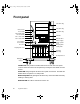
8505945.book Page 2 Thursday, March 9, 2000 2:13 PM Front panel 5.25” drive bay 5.25” drive bay Chassis lock Power LED Disk activity LED Reserved LED PS 1 status LED PS 2 status LED Reset button Power button Reserved 5.
8505945.book Page 3 Thursday, March 9, 2000 2:13 PM PS1 status LED that glows green when the first power supply module in the redundant power supply is installed and working correctly. It flashes green if the power supply module fails or one of its power levels goes out of bounds. If the power supply module is not installed, this LED is off. The LED is only active on systems using the Redundant N+1 power supply.
8505945.book Page 4 Thursday, March 9, 2000 2:13 PM Back panel Power supply module Module power switch Power connector Power supply cable clamp Module power switch Keyboard port Power supply module LED Power supply module Redundant power supply Mouse port Serial port A Parallel port Serial port B Network port USB ports Video port Expansion card slots Expansion card retention clips Kensington lock slot Module power switches (2) provide independent power control for each redundant power supply module.
8505945.book Page 5 Thursday, March 9, 2000 2:13 PM PS/2 power supply (not shown) provides sufficient power to run the server at a reduced cost. Mouse port connects a PS/2-compatible mouse. Parallel port connects a printer or other parallel device. Network port lets you connect to a network. The adjacent indicator LEDs show LAN activity (yellow) and 100 Mbit speed (green).
8505945.book Page 6 Thursday, March 9, 2000 2:13 PM Interior of system Power supply Power supply fans 5.25-inch drive bays 3.25-inch drive bays Hot-plug bays (Hot-plug cage) Outriggers Castors Back panel fan System board System board tray Hot-plug cage fan Hot-plug backplane Power supply provides power to the system components. The redundant power supply provides hot-swap capability and fault tolerance.
8505945.book Page 7 Thursday, March 9, 2000 2:13 PM Hot-plug backplane provides the control for the hot-plug drives. Hot-plug cage fan provides cooling for the hot-plug drives and other internal components. System board tray supports the system board and makes it easier to remove and install. System board see “System board” on page 8. Back panel fan provides cooling for system board components and additional cooling for the power supply.
8505945.
8505945.
8505945.
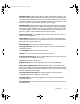
8505945.book Page 11 Thursday, March 9, 2000 2:13 PM Hot-plug backplane Back of the hot-plug backplane board JP5: Delay start jumper Power connector SCSI connector JP6: Termination jumper JP5: Delay start jumper controls the spin-up sequence of the drives attached to the backplane. If you enable delay start, the drives spin up one at a time in order of their SCSI ID. If you disable delay start, all drives spin up simultaneously. Set the jumper according to the table below.
8505945.book Page 12 Thursday, March 9, 2000 2:13 PM JP6: Termination jumper enables or disables termination for the backplane. The backplane is designed to occupy one end of the bus and is usually terminated. If you configure the SCSI bus so the backplane is not at the end of the bus, disable termination. Set the jumper according to the table below.
8505945.book Page 13 Thursday, March 9, 2000 2:13 PM Front panel board The front panel board supports the LEDs and buttons accessible from the front panel. The buttons and LEDs on the front panel board are shown and described below. Power LED Disk activity LED Reserved LED NMI button PS 1 status LED PS 2 status LED Chassis intrusion detection switch Front panel connector Power supply alarm speaker reset button Reset button Power button Power LED that glows green whenever the system is turned on.
8505945.book Page 14 Thursday, March 9, 2000 2:13 PM Power button turns the server on and off. In an ACPI-enabled operating system like Windows 2000, you can set the power button to enter sleep mode rather than turning the system off. Power supply alarm speaker reset button disables the power supply alarm speaker. The alarm is not cleared and the appropriate LED continues to glow until the failed power supply module is replaced. The alarm is only active on systems using the N+1 redundant power supply.
8505945.book Page 15 Thursday, March 9, 2000 2:13 PM 2 System Setup Setting up the server Use the instructions on the quick guide poster that came with the server to assemble the server. You can prepare a safer working environment before assembling the server by following these guidelines: ■ Use a clean, flat, and stable surface for the server. Allow at least 12 inches at the rear of the computer for cabling and air circulation. ■ Obtain an adequately rated uninterruptible power supply (UPS).
8505945.book Page 16 Thursday, March 9, 2000 2:13 PM Installing the outriggers and castors The tower chassis is shipped with small rubber feet to prevent it from slipping and to minimize vibrations when the chassis is placed on a desktop. However, if you intend to place the chassis on the floor, you may find it easier to maintain the system if it has castors and can be rolled out for easier access. To install the outriggers and castors: 1 Gently turn the chassis upside down, placing it on the top panel.
8505945.book Page 17 Thursday, March 9, 2000 2:13 PM 3 Place the tabs on the outriggers into the corresponding slots on the bottom panel and slide the outriggers toward the ends of the chassis. 4 Carefully return the chassis to the upright position. Starting the server Before you start the server for the first time: ■ The redundant power supply is autosensing. It automatically determines the voltage of the incoming power source and compensates accordingly.
8505945.book Page 18 Thursday, March 9, 2000 2:13 PM 4 Turn on any other components connected to the computer, such as speakers, a printer, or a scanner. If nothing happens when you turn on the system: ■ Make sure that the power cables are securely plugged in and that the power strip or UPS (if you are using one) is plugged in and turned on. ■ Make sure the monitor is connected to the computer, plugged into the power strip, AC outlet, or UPS, and turned on.
8505945.book Page 19 Thursday, March 9, 2000 2:13 PM 4 If you need to return to the previous dialog box to change any of your entries, click Back. 5 Restart the server. The setup is complete. Important For other operating systems, such as Windows® 2000 or Novell® Netware, refer to the appropriate operating system software manual. Turning off the server Every time you turn off the server, shut down the operating system first. You may lose data if you do not follow the proper procedure.
8505945.book Page 20 Thursday, March 9, 2000 2:13 PM Resetting the server If your computer does not respond to keyboard or mouse input, you may have to close programs that are not responding. If closing unresponsive programs does not restore your computer to normal operation, you may have to reset the system. To close unresponsive programs and reset the server in Windows NT: 1 Press CTRL+ALT+DEL. A window opens that lets you close a program that is not responding.
8505945.book Page 21 Thursday, March 9, 2000 2:13 PM Case Access 3 The Gateway 7210 Server is designed as a toolless chassis. None of the normal user-serviceable parts require a tool of any kind to remove, install, or replace. In some cases, where the pieces fit very tightly, a tool may make the job easier. The various clips, tabs, thumbscrews, and other devices that allow toolless construction are color-coded in green to show you where they are.
8505945.book Page 22 Thursday, March 9, 2000 2:13 PM Preventing static electricity discharge Before opening the computer case, follow these precautions to prevent damage from static electricity. When opening your computer case, always perform the following procedure. Caution Static electricity can permanently damage electronic components in your computer. Prevent electrostatic damage to your computer by following static electricity precautions every time you open your computer case.
8505945.book Page 23 Thursday, March 9, 2000 2:13 PM Opening the case Important All references to front, back, left, or right on the computer are based on the computer being in a normal, upright position, as viewed from the front. The only components that are accessible from outside of the chassis are the front panel indicator lights. To access any of the removable media drives, the hot-plug drives, or the power and reset switches you must open the bezel door.
8505945.book Page 24 Thursday, March 9, 2000 2:13 PM Opening the bezel door The bezel door covers the removable media drives, the hot-plug drives, and the front panel controls. To access these components, you must open the bezel door. To open the bezel door: 1 If the bezel door is locked, unlock it. 2 Grip the bezel door handle next to the front panel indicator lights and pull the door open.
8505945.book Page 25 Thursday, March 9, 2000 2:13 PM Removing the front bezel The locking front bezel provides secure access to the system components. You must unlock and remove the front bezel before you can remove the side panel and access the interior of the system. To remove the front bezel: 1 Power down, turn off, and disconnect all power to the server. 2 Observe all safety and static electricity precautions, see “Preventing static electricity discharge” on page 22.
8505945.book Page 26 Thursday, March 9, 2000 2:13 PM Removing the side panel The side panel cannot be removed unless the front bezel has already been removed. The side panel provides access to all of the internal components of the server. To remove the side panel: 1 Turn off the computer and disconnect all power cords. 2 Observe all safety and static electricity precautions, see “Preventing static electricity discharge” on page 22.
8505945.book Page 27 Thursday, March 9, 2000 2:13 PM Closing the case Close the chassis as soon as you finish installing or removing components so that dust and dirt do not collect inside the computer. Replacing the side panel Closing the side panel covers the internal components. You must close the side panel and replace the front bezel before you can operate the server. If you do not, a system intrusion event is logged by the system management hardware.
8505945.book Page 28 Thursday, March 9, 2000 2:13 PM 4 Tighten the thumbscrews.
8505945.book Page 29 Thursday, March 9, 2000 2:13 PM Replacing the front bezel Once the side panel is in place, you must replace the bezel to operate the server. If the server is run without the bezel installed, a chassis intrusion event is logged by the system management hardware. To replace the front bezel: 1 Holding the bezel at an angle to the front of the chassis, place the hinge slot on the bottom of the bezel over the flange on the bottom edge of the chassis.
8505945.book Page 30 Thursday, March 9, 2000 2:13 PM Closing the bezel door Close the bezel door to prevent accidental or unauthorized access to the server controls, hot-plug drives, and removable media drives. To close the bezel door: 1 Swing the bezel door to the left and press it firmly into place. 2 Lock it if necessary.
8505945.book Page 31 Thursday, March 9, 2000 2:13 PM Replacing and Adding Internal Devices 4 The Gateway 7210 Server is designed as a toolless chassis. None of the normal user-serviceable parts require a tool of any kind to remove, install, or replace. In some cases, where the pieces fit very tightly, a tool may make the job easier. The various clips, tabs, thumbscrews, and other devices that allow toolless construction are color-coded in green to show you where they are.
8505945.book Page 32 Thursday, March 9, 2000 2:13 PM Drives There are several types of drives and similar devices that can be installed in the server. All drives are easy to install and require no tools to replace. Preparing to replace or add a drive One 3.5-inch diskette drive, one 3.5-inch hot-plug hard drive, and one CD drive are included with the computer. You can add additional drives of the following types: ■ 1-inch high, 3.5-inch hot-plug drives. ■ Half-height 3.
8505945.book Page 33 Thursday, March 9, 2000 2:13 PM Drive cabling information The system includes five different types of drive cables. Each drive cable is clearly labeled, indicating the cable type and showing which end to connect to the appropriate connector on the system board and which end to connect to the drive. ■ Use the diskette drive connector cable to connect the diskette drive. ■ Use the standard IDE connector cable to connect IDE devices such as CD drives and standard IDE hard drives.
8505945.book Page 34 Thursday, March 9, 2000 2:13 PM 5 Disengage the rail locking tabs by pressing in on both front rail extensions, then move the drive slightly out of the bay by pushing on the back of the drive. 6 Pull the drive out of the chassis. 7 Remove the rails on both sides of the drive and snap them onto the new drive in the same positions. The rails are labeled. Make sure the front rail extensions are towards the front of the drive. Important The rails on the 3.
8505945.book Page 35 Thursday, March 9, 2000 2:13 PM Replacing the optional boot drive An optional IDE hard drive can be shipped with the server. This drive is mounted at the bottom of the drive stack accessible from the front of the chassis. To replace the optional boot drive: 1 Turn off the system and disconnect the power cord and all other external peripheral devices. 2 Open the case. (See “Opening the case” on page 23 and “Preventing static electricity discharge” on page 22.) 3 Locate the 3.
8505945.book Page 36 Thursday, March 9, 2000 2:13 PM 8 Install the two drive mounting rails to the new hard drive, making sure the front rail extensions are towards the front of the device. The rails are labeled. 9 Align the rails with the open bay at the bottom of the drive stack, then slide the drive into the stack until the locking tabs snap into place (make sure that the data and power connectors on the drive face the inside of the server). 10 Connect the power and data cables to the drive.
8505945.book Page 37 Thursday, March 9, 2000 2:13 PM Replacing a hot-plug drive The hot-plug drives are located at the bottom of the front panel. The hot-plug bay supports as many as six 1-inch high 3.5-inch SCA-II SCSI hard drives. The hot-plug drives are assigned SCSI ID numbers by the hot-plug backplane with the drive at the far left side of the hot-plug bay assigned SCSI ID 0. The backplane assigns SCSI IDs to the other drives in order up to SCSI ID 5 at the far right side of the hot-plug bay.
8505945.book Page 38 Thursday, March 9, 2000 2:13 PM To replace a failed drive: 1 Before you remove the failed drive, use the appropriate software and utilities installed on the system to stop all activity on the failed drive. Instructions for using the software are provided by the software manufacturer. 2 Use the utilities to determine which drive needs to be replaced. 3 If the drive carrier is locked, use the hex key to unlock the carrier.
8505945.book Page 39 Thursday, March 9, 2000 2:13 PM 5 Continue pulling outward until the drive is entirely out of the system.
8505945.book Page 40 Thursday, March 9, 2000 2:13 PM 6 Remove the four screws that secure the drive to the carrier, then remove the drive. 7 Install the new drive in the carrier using the four screws you removed in Step 6. 8 Align the drive rails with the slots at the top and bottom of the drive bay. Leave the handle in the down position. 9 Push the drive all of the way into the drive bay until the handle starts to close because of contact with the front of the chassis.
8505945.book Page 41 Thursday, March 9, 2000 2:13 PM 11 Run any necessary utilities to inform the system that the new drive is installed and ready for use. See the utility software documentation for details. Adding a hot-plug drive The hot-plug drives are located at the bottom of the front panel. The hot-plug bay supports up to six 1-inch high 3.5-inch SCA LVD SCSI hard drives.
8505945.book Page 42 Thursday, March 9, 2000 2:13 PM Removing an empty drive carrier If the system ships with less than six drives installed, the empty drive bays contain drive carriers. To remove a drive carrier, follow the instructions to remove a drive in “Replacing a hot-plug drive” on page 37. Purchase additional SCSI drives through your Gateway sales representative. Specify the system into which you will install the drive to ensure that the correct drive is delivered.
8505945.book Page 43 Thursday, March 9, 2000 2:13 PM 3 Continue pulling outward until the drive carrier is entirely out of the system.
8505945.book Page 44 Thursday, March 9, 2000 2:13 PM Installing a SCSI drive in the server You do not need to configure individual drives before you install them in the server. To install a SCSI drive in the server: 1 Remove the empty drive carrier as described in “Removing an empty drive carrier” on page 42. 2 Remove the four screws that secure the support bracket and front assembly to the rails. The two screws that secure the front assembly are threaded through small nuts.
8505945.book Page 45 Thursday, March 9, 2000 2:13 PM 3 Install the drive into the carrier using the four screws you removed in Step 2. 4 Align the drive rails with the slots at the top and bottom of the drive bay.
8505945.book Page 46 Thursday, March 9, 2000 2:13 PM 5 Leave the handle down and push the drive all of the way into the drive bay until the handle begins to close because of contact with the front edge of the server. 6 Make sure the hooks on the bottom of the handle latch over the edge of the drive bay, then firmly close the handle. 7 Secure the drive by locking the drive carrier with the hex key. Replacing the CD drive The CD drive is located in one of the 5.
8505945.book Page 47 Thursday, March 9, 2000 2:13 PM 4 Remove the power and data cables from the back of the drive, noting their locations and orientations. (You will reconnect these cables after you install the new drive.) 5 Disengage the rail locking tabs by pressing in on both front rail extensions, then move the drive slightly out of the bay by pushing on the back of the drive. 6 Pull the drive out of the chassis.
8505945.book Page 48 Thursday, March 9, 2000 2:13 PM Adding additional 5.25-inch devices You can use the three additional, externally accessible 5.25-inch drive bays to install additional 5.25-inch devices such as a CD writer or a tape backup drive. Use the rails from the existing filler trays to install new drives. You may need to purchase an additional cable of sufficient length to connect the existing devices and the new device to the connector on the system board. To install an additional 5.
8505945.book Page 49 Thursday, March 9, 2000 2:13 PM 6 Connect the power and data cables, making sure the cables are in their original positions. (See the drive documentation for proper cable orientations.) 7 Close the case. (See “Closing the case” on page 27.) 8 Reconnect the power cord and all other external peripheral devices, then turn on the system. 9 Run the configuration software, if required.
8505945.book Page 50 Thursday, March 9, 2000 2:13 PM Memory Four DIMM sockets on the system board support up to 2.0 Gigabytes (GB) of PC/100 SDRAM. Replacing memory The DRAM DIMMs supported by the system board conform to the following standards: ■ 64 MB, 128 MB, 256 MB, and 512 MB ECC DIMMs ■ PC/100-compliant, unbuffered, ECC SDRAM ■ 64 MB minimum system memory ■ 2.
8505945.book Page 51 Thursday, March 9, 2000 2:13 PM 4 Insert the new DIMM into the socket and align the two notches in the DIMM with the two notches in the DIMM socket. 5 Gently press the DIMM into the socket until it is firmly seated. Inserting the DIMM automatically locks the socket clamps on each end of the DIMM. 6 Close the case. (See “Closing the case” on page 27.) 7 Reconnect the peripherals and the power cord, then turn on the system.
8505945.book Page 52 Thursday, March 9, 2000 2:13 PM Adding memory The DRAM DIMMs supported by the server board conform to the following standards: ■ 64 MB, 128 MB, 256 MB, and 512 MB ECC DIMMs ■ PC/100-compliant, unbuffered, ECC SDRAM ■ 64 MB minimum system memory ■ 2.0 GB maximum system memory When you select and install DIMMs, keep the following in mind: ■ Registered DIMMs should not be combined with unbuffered DIMMs ■ Memory should be added in order, from DIMM 1 to DIMM 4.
8505945.book Page 53 Thursday, March 9, 2000 2:13 PM 5 Gently press the DIMM into the socket until it is firmly seated. Inserting the DIMM automatically locks the socket clamps on each end of the DIMM. 6 Close the case. (See “Closing the case” on page 27.) 7 Reconnect the peripherals and the power cord, then turn on the system. Processors The system is compatible with the Intel® Pentium® III 600 MHz and faster processors with 100 MHz front-side bus (FSB).
8505945.book Page 54 Thursday, March 9, 2000 2:13 PM 5 Push the handle of the screwdriver toward the processor. When the tab that locks the processor in place opens, lift up slightly on the side of the processor. 6 Repeat the previous two steps for the other side of the processor. 7 Pull the processor up and out of the slot.
8505945.book Page 55 Thursday, March 9, 2000 2:13 PM 8 Align the new processor with the processor slot (note that the processor slot is keyed so the processor can only be installed one way) and press firmly to install it. 9 Reconnect the processor fan cable to the processor fan connector on the system board. 10 Close the case. (See “Closing the case” on page 27.) 11 Reconnect the power cord and all other cords you removed, then turn on the system.
8505945.book Page 56 Thursday, March 9, 2000 2:13 PM Adding a processor The system is compatible with the Intel® Pentium® III 600 MHz and faster processors with 100 MHz front-side bus (FSB). As many as two processors may be installed in the system. The second processor must match the first processor in speed or the system functions at the speed of the slowest processor. When adding a second processor order a processor upgrade kit from Gateway.
8505945.book Page 57 Thursday, March 9, 2000 2:13 PM 4 Align the new processor with the processor slot. Note that the processor slot is keyed so the processor can only be installed one way. Press it firmly to install it. 5 Connect the processor fan cable to the second processor fan connector on the system board (See “System board” on page 8 for location). 6 Close the case. (See “Closing the case” on page 27.) 7 Reconnect the power cord and all other cords you removed, then turn on the system.
8505945.book Page 58 Thursday, March 9, 2000 2:13 PM Replacing the battery The battery provides power for the system real-time clock and CMOS memory, which holds the system configuration information. If your battery is failing you may notice the server clock slowing down and giving you the incorrect time. Open the BIOS Setup utility and write down all the values in the various menus before replacing the battery. Replacing the battery resets the BIOS Setup utility to its default values.
8505945.book Page 59 Thursday, March 9, 2000 2:13 PM 3 Turn off the computer, disconnect the power cord and all external peripheral devices. 4 Open the case by following the instructions on page 23. (See “Preventing static electricity discharge” on page 22.) 5 Locate the battery on the system board (see “System board” on page 8). The battery is circular and has the positive pole mark (+) on the top.
8505945.book Page 60 Thursday, March 9, 2000 2:13 PM 60 ■ Turn off the computer, remove the cover, and make sure that all cables inside the case are attached securely. Also, make sure that the colored cable edges are aligned correctly and that the connectors did not miss any pins. Disconnect and reconnect the cables. Close the case as described in “Closing the case” on page 27, reconnect the modem and power cords, then turn on the computer.
8505945.book Page 61 Thursday, March 9, 2000 2:13 PM Expansion cards The server has seven expansion slots on the system board that may be used for a variety of expansion cards. Four slots support 32-bit, 33 MHz PCI cards, two slots support 32-bit, 66 MHz PCI cards, and one slot supports an ISA card. All slots support the installation of full-length cards. Replacing an expansion card To replace an expansion card: 1 Set any jumpers and switches on the replacement card, if required in the card instructions.
8505945.book Page 62 Thursday, March 9, 2000 2:13 PM Expansion card retention clip Card guide release tab 7 Place the replacement card in the slot and press it firmly into the connector. 8 Once the card is securely placed, slide the card guide release tab down again (for full-length expansion cards) and press the expansion card retention clip through the back panel until it clicks into place to secure the card. 9 Connect any cables to the card (see card documentation for proper cable orientation).
8505945.book Page 63 Thursday, March 9, 2000 2:13 PM Adding an expansion card To add an expansion card: 1 Set any jumpers and switches on the card, if required in the card instructions. 2 Turn off the computer, disconnect the power cord and all external peripheral devices. 3 Open the case. (See “Opening the case” on page 23 and “Preventing static electricity discharge” on page 22.
8505945.book Page 64 Thursday, March 9, 2000 2:13 PM Expansion card retention clip Card guide release tab 8 Once the card is securely placed, slide the card guide release tab down again (for full-length expansion cards) and press the expansion card retention clip through the back panel until it clicks into place to secure the card. 9 Connect any cables to the card (see card documentation for proper cable orientation). 10 Close the case. (See “Closing the case” on page 27.
8505945.book Page 65 Thursday, March 9, 2000 2:13 PM Power supplies The Gateway 7210 Server supports two power supplies. The basic model uses a single power supply of the same size and type as those used in most desktop PCs. The optional upgrade provides an N+1 redundant power supply that offers fault tolerance and hot-swap capability. This section describes replacing both power supplies and also describes the procedure for hot-swapping a power supply module in the N+1 redundant power supply.
8505945.book Page 66 Thursday, March 9, 2000 2:13 PM 3 Press the locking tab toward the center of the module while carefully pulling the failed module out of the power supply. Locking tab A B Thumbscrew 4 Carefully insert the new power supply module into the vacant slot, pressing firmly to seat the connector at the back. 5 Tighten the thumbscrew to secure the new module in position.
8505945.book Page 67 Thursday, March 9, 2000 2:13 PM A B Replacing the redundant power supply The redundant power supply offers fault tolerance and hot-swap capabilities. However, if the power distribution board at the base of the power supply or some other shared component fails, the entire power supply and its housing must be replaced. A failure of a shared component is indicated by both power supply status LEDs flashing and an audible alarm, or the system will fail to power up.
8505945.book Page 68 Thursday, March 9, 2000 2:13 PM 5 While supporting the power supply by the handle with one hand, remove the screws securing the power supply to the back panel. Handle 6 Carefully lift the power supply out of the chassis using the handle attached to the power supply. Move the power supply forward to clear the support bracket, then tilt the left side of the power supply down to clear the side cover mounting rail as you pull it out.
8505945.book Page 69 Thursday, March 9, 2000 2:13 PM 8 Place the new power supply in the proper position in the chassis and line up the mounting holes with the holes in the chassis. Handle 9 Replace the screws securing the power supply to the back panel. 10 Reconnect the power connectors to the system board and to all internal devices. 11 Close the case. (See “Closing the case” on page 27.) 12 Reconnect the power cord and all external peripherals, then turn on the system.
8505945.book Page 70 Thursday, March 9, 2000 2:13 PM Replacing the PS/2 power supply The PS/2 power supply does not support fault tolerance or hot-swapping. If the power supply fails, you must replace it. To replace the PS/2 power supply: 1 Turn off the system and disconnect the power cord and all peripherals. 2 Open the case. (See “Opening the case” on page 23 and “Preventing static electricity discharge” on page 22.) 3 Disconnect the power supply connectors from all internal devices, including the 3.
8505945.book Page 71 Thursday, March 9, 2000 2:13 PM 6 Carefully lift the power supply out of the chassis, moving it forward to clear the support bracket and dropping it down slightly to clear the side mounting rail. 7 Make sure that the new power supply matches the one you removed. The mounting holes should line up correctly, and the specifications and power output connectors should be the same.
8505945.book Page 72 Thursday, March 9, 2000 2:13 PM Replacing the back panel and hot-plug cage fans The back panel fan is located below the power supply on the back panel. The hot-plug cage fan is located behind the hot-plug cage, between the hot-plug cage and the system board. See the illustration on page 6 for more information. To remove the back panel fan: 1 Turn off the system and disconnect the power cord and external peripherals. 2 Open the case.
8505945.book Page 73 Thursday, March 9, 2000 2:13 PM 4 Carefully remove the fan from the chassis. 5 Disconnect the fan power cable from the connector on the system board. Note the connector it was attached to. 6 Place the new fan bracket unit into the chassis by engaging the two retaining tabs with the tabs on the back panel of the chassis and the release tabs with the slots in the back panel. 7 Connect the fan power cable to the appropriate connector on the system board. 8 Close the case.
8505945.book Page 74 Thursday, March 9, 2000 2:13 PM Replacing the control panel board The control panel board is mounted on the front of the chassis, behind the front bezel. To replace the control panel board: 1 Turn off the system and disconnect the power cord and all external peripherals. 2 Open the case. (See “Opening the case” on page 23 and “Preventing static electricity discharge” on page 22.) 3 Disconnect the front panel connector from the control panel board.
8505945.book Page 75 Thursday, March 9, 2000 2:13 PM 8 Plug the control panel cable into the connector on the control panel board. 9 Close the case. (See “Closing the case” on page 27.) 10 Reconnect the power cord and the external peripherals, then turn on the system. Replacing the hot-plug backplane The six drive hot-plug backplane is at the back of the hot-plug drive cage. The backplane supports as many as six hot-swappable LVD SCSI drives. The backplane provides activity LEDs for each drive.
8505945.book Page 76 Thursday, March 9, 2000 2:13 PM 6 Pull the backplane out to the side of the chassis, then toward the back of the system to remove it from the retention hooks. 7 Lift the backplane out of the chassis. 8 Set any jumpers on the new backplane that are required for your SCSI configuration. (See “Hot-plug backplane” on page 11 for instructions.
8505945.book Page 77 Thursday, March 9, 2000 2:13 PM 9 Place the backplane onto the hot-plug cage bracket, making sure the hooks on the bracket fit into the slots on the backplane. 10 When the backplane is securely in place, tighten the two captive thumbscrews. 11 Reconnect all cables on the backplane to the correct connectors. 12 Replace all hot-plug drives. Be careful to replace them in the same slots that they were in before you removed them. 13 Close the case. (See “Closing the case” on page 27.
05945.book Page 78 Thursday, March 9, 2000 2:13 PM Replacing the system board The system board is the heart of the computer, which integrates the other elements of the system, such as the processor, memory, storage, networking, and communications, and lets them operate in a coordinated and useful way. Important All references to front, rear, left, or right on the computer are based on the computer being in a normal, upright position, as viewed from the front.
8505945.book Page 79 Thursday, March 9, 2000 2:13 PM 7 Loosen the retaining thumbscrew securing the board support tray to the right side of the chassis. Retaining thumbscrew 8 Slide the board support tray toward the front of the chassis slightly to disengage it from the stand-off retention hooks.
8505945.book Page 80 Thursday, March 9, 2000 2:13 PM 9 Using the handle at the bottom of the board support tray, pull the back edge of the system board (the edge against the back panel) out of the chassis. 10 Remove the system board from the support tray by removing the seven screws and snapping it off of the two snap-on standoffs, then place the board in an anti-static bag or container. 11 Install the replacement system board on the tray.
8505945.book Page 81 Thursday, March 9, 2000 2:13 PM 12 Holding the board support tray by the handles, place it in the chassis right edge first as shown in the illustration below. Arrange the cables carefully to prevent tangling as you install the board and tray assembly. 13 Holding the board support tray in place, tighten the retaining screw on the right edge of the board support tray. 14 Replace the back panel fan (see “Replacing the back panel and hot-plug cage fans” on page 72).
8505945.
8505945.book Page 83 Thursday, March 9, 2000 2:13 PM 5 Using the BIOS Setup Utility About the BIOS Setup utility The server BIOS has a built-in setup utility that lets you configure several basic system characteristics. The settings are stored in battery-backed RAM and are retained even when the power is off. Enter the BIOS Setup utility by restarting the computer, then pressing F2 when prompted during the startup process. The Main BIOS Setup utility screen opens.
8505945.book Page 84 Thursday, March 9, 2000 2:13 PM As you select items on the Main menu or in submenus, you see specific information related to the current selection in the Item Specific Help box. The command bar shows the keystrokes necessary to access help, navigate through the menus, and perform other functions. ■ F1 opens the Help screen, providing general help for using the BIOS Setup utility. ■ The ↑ (up arrow) and ↓ (down arrow) keys select items in the menu.
8505945.book Page 85 Thursday, March 9, 2000 2:13 PM Updating the BIOS If you need a new version of the BIOS, you can download the BIOS update from technical support on the Gateway Web site (www.gateway.com) and install the new version from a diskette.
8505945.book Page 86 Thursday, March 9, 2000 2:13 PM Setting the system board jumpers The system board has three jumpers. Each of these jumpers has a specific function described in the sections below. The CMOS Clear jumper The CMOS Clear jumper on the system board (pins 1 through 3 of jumper J2J1) lets you clear all BIOS Setup settings. (See the figure on page 8 for the location of the jumper.) The following table shows the settings required to perform this task.
8505945.book Page 87 Thursday, March 9, 2000 2:13 PM The following table shows the settings required to perform this task. Make sure you turn off the computer and unplug the power cord before moving the jumper. Mode Jumper Setting Protect Action When Set Normal operation (default) Pins 5-6 Clear Clears all passwords at bootup Pins 6-7 Caution Moving the jumper while the power is on can damage the server. Always turn off the server and unplug the power cord before changing the jumper.
8505945.book Page 88 Thursday, March 9, 2000 2:13 PM BIOS Boot Block Write Enable jumper The BIOS Boot Block Write Enable jumper on the system board (pins 13 through 15 of jumper J2J1) lets you update the BIOS boot block. (See the figure on page 8 for the location of the jumper.) Caution Incorrect programming of the boot block may leave the system unbootable. The following table shows the settings required to perform this function.
8505945.book Page 89 Thursday, March 9, 2000 2:13 PM The following table shows the settings required to allow programming of the BMC boot block. Make sure you turn off the computer and unplug the power cord before moving the jumper.. Mode Jumper Setting Normal Pins 1-2 Writes enabled Pins 2-3 Caution Action When Set BMC boot block is write protected (default) Allows BMC boot block to be programmed through the correct utilities. Moving the jumper while the power is on can damage the server.
8505945.book Page 90 Thursday, March 9, 2000 2:13 PM Intrusion Detection Enable jumper The Intrusion Detection Enable jumper on the system board (pins 5 through 7 on jumper J3J1) lets you enable intrusion detection. (See the figure on page 8 for the location of the jumper.) The following table shows the settings required to enable intrusion detection. Make sure you turn off the computer and unplug the power cord before moving the jumper.
8505945.book Page 91 Thursday, March 9, 2000 2:13 PM Mode Jumper Setting Normal Action When Set Normal boot (default) Pins 9-10 Update BMC System updates BMC Pins 10-11 Caution Moving the jumper while the power is on can damage the server. Always turn off the server and unplug the power cord before changing the jumper. WOL Enable jumper The WOL Enable jumper on the system board (jumper J5A2) lets you enable the wake-on-LAN feature. (See the figure on page 8 for the location of the jumper.
8505945.
8505945.book Page 93 Thursday, March 9, 2000 2:13 PM Managing the Server 6 Avoiding power source problems Surge suppressors, line conditioners, and uninterruptible power supplies can help protect the server against power source problems. Surge suppressors During a power surge, the voltage level of electricity coming into the server can increase far above normal levels and cause data loss or system damage.
8505945.book Page 94 Thursday, March 9, 2000 2:13 PM Line conditioners A line conditioner protects the server from the small fluctuations in voltage from an electrical supply. Most systems can handle this variation (or line noise) without problems. However, some electrical sources include more line noise than normal. Line noise can also be a problem if the server is located near, or shares a circuit with, a device that causes electromagnetic interference, such as a television or a motor.
8505945.book Page 95 Thursday, March 9, 2000 2:13 PM Use Check Disk from once a week to once a month, depending on how often you use the server. Also use Check Disk if you have any hard drive problems. To use Check Disk: 1 Double-click the My Computer icon. The My Computer window opens. 2 Right-click the drive you want to check. 3 Select Properties. The drive’s properties window opens. 4 Click the Tools tab. 5 At Error-checking, click Check Now. The Check Disk window opens.
8505945.book Page 96 Thursday, March 9, 2000 2:13 PM Backing up files Regularly backing up your files protects you from losing data and lets you keep fewer files on your hard drive. Back up old files to a large capacity disk drive or tape drive and delete the files from your hard drive. You can use the software that came with your tape backup drive or your large capacity disk drive to back up the files. You can also back up files by running the Backup utility that came with your operating system.
8505945.book Page 97 Thursday, March 9, 2000 2:13 PM Deleting temporary Internet files As you visit Web sites, your browser stores temporary Internet files on your hard drive in a memory cache and a disk cache. Files in the memory cache are removed when you turn off your computer. Files are saved in the disk cache until the space designated for the cache is full. See your browser’s Help files for instructions on emptying the disk cache.
8505945.book Page 98 Thursday, March 9, 2000 2:13 PM Protecting the server against viruses A virus is a program that attaches itself to a program or data file on a computer, then spreads from one computer to another. Viruses can damage data, cause computers to malfunction, and can display annoying or offensive messages. Some viruses can go unnoticed for long periods of time because they are activated by a certain date or time.
8505945.book Page 99 Thursday, March 9, 2000 2:13 PM System administration and control The server has three server-management tools included to enable administration and control of Windows NT environments. These tools are Intel® Server Control (ISC), ManageX Event Manager, and the Direct Platform Control (DPC) Console. Intel Server Control (ISC) Using a graphical user interface, ISC can locally or remotely provide real-time monitoring and alerting for server hardware sensors.
8505945.book Page 100 Thursday, March 9, 2000 2:13 PM Direct Platform Control (DPC) Console The Direct Platform Control (DPC) Console provides remote emergency management of servers. The DPC Console is independent of the server operating system and provides a means to remotely diagnose problems or verify the state of the server. It will also turn the server on or off. You can find additional information about DPC Console under Documentation on the 7210 Companion CD which came with the system.
8505945.book Page 101 Thursday, March 9, 2000 2:13 PM Using passwords If you set and enable a user password but not an administrator password, enter the user password to boot the system with limited BIOS Setup access.
8505945.book Page 102 Thursday, March 9, 2000 2:13 PM Summary of software security features The following table lists the software security features and describes what protection each offers. In general, to enable or set the features listed here, you must run the BIOS Setup utility and go to the Security Menu. The table also refers to other Setup utility menus. For more information on setting the security features, see “About the BIOS Setup utility” on page 83.
8505945.book Page 103 Thursday, March 9, 2000 2:13 PM Feature Description Control access to the BIOS Setup (set administrator password) To control access to the system configuration, set an administrator password and enable it through Setup. If both the administrator and user passwords are enabled, either can be used to boot the system or enable the keyboard and/or mouse, but only the administrator password allows changes to Setup.
8505945.book Page 104 Thursday, March 9, 2000 2:13 PM System recovery Take precautions that allow you to recover damaged files and recover your system in the event that your hard drive is damaged, or if your BIOS or system files get corrupted. Creating a startup diskette If your computer hard drive is damaged, you may not be able to start the computer from the hard drive. A startup diskette is a bootable diskette that lets you start the computer and attempt to fix the problem.
8505945.book Page 105 Thursday, March 9, 2000 2:13 PM 7 Troubleshooting Introduction If the server does not operate correctly, re-read the instructions for the procedures you have performed. If an error occurs within an application, refer to the documentation supplied with the software. This section identifies solutions to some possible problems. Troubleshooting checklist Before turning on the system, make sure that: ■ The power cord is connected to the AC power-in connector and an AC outlet.
8505945.book Page 106 Thursday, March 9, 2000 2:13 PM Troubleshooting guidelines As you troubleshoot the server, keep the following guidelines in mind: ■ Never remove the chassis cover while the computer is turned on. ■ Do not attempt to open the monitor; it is extremely dangerous. Even if the power is disconnected, stored energy in the components can be dangerous. ■ If a peripheral does not work, make sure that all connections are secure.
8505945.book Page 107 Thursday, March 9, 2000 2:13 PM Probable cause Solution The sound card may not be installed correctly Open the system, then reseat the sound card. Make sure that the cables are connected properly. Some systems do not have sound cards because sound capabilities are built into the system board. The CD drive audio cable may be installed incorrectly Open the system and make sure that the cables are connected properly.
8505945.book Page 108 Thursday, March 9, 2000 2:13 PM Hard drive problems The system does not recognize the SCSI drive Probable cause Solution SCSI hot-plug drive is not seated correctly Open the system and reseat the hot-plug drive(s). This problem is most common immediately after shipping. The SCSI bus is not properly terminated Open the system and make sure that the last device on the SCSI chain is properly terminated.
8505945.book Page 109 Thursday, March 9, 2000 2:13 PM Memory and processor problems The system detected memory errors during start up Probable cause Solution Memory was added or removed, and the new configuration was not saved in the BIOS Setup utility Open the BIOS Setup utility and save the new memory configuration. The memory was installed incorrectly Make sure that the memory is proper seated and oriented. A memory chip is faulty Replace the card with the faulty chip.
8505945.book Page 110 Thursday, March 9, 2000 2:13 PM Modem problems The system does not recognize the modem Probable cause Solution The modem has not been added as new hardware Add the modem as new hardware. The modem is not connected to a live phone jack Make sure that the line connected to the modem is working and plugged into the appropriate port on the modem (line port).
8505945.book Page 111 Thursday, March 9, 2000 2:13 PM The system does not recognize the diskette drive Probable cause Solution The diskette drive may be configured incorrectly Restart your computer, then press F1 to enter the BIOS Setup utility. In the Boot | Removable Devices menu, make sure that the diskette drive parameters are set correctly. The drive cables are not connected properly Open the system, then make sure all cables are properly connected to the controller card.
8505945.book Page 112 Thursday, March 9, 2000 2:13 PM The system does not recognize an expansion card Probable cause Solution The interrupt or I/O address is set incorrectly Check the address configuration of the adapter card and make sure that it does not conflict with another card in the system. The card has not been configured through the software Configure the card with the appropriate software.
8505945.book Page 113 Thursday, March 9, 2000 2:13 PM Probable cause Solution The printer has not been added to the system In the Printers window (Start | Settings | Printers), double-click Add Printer. Follow the on-screen instructions for adding the new printer. The printer prints garbled text Probable cause Solution The wrong driver is being used for the selected printer In the Printers window (Start | Settings | Printers), select the printer. From the File menu, click Properties.
8505945.book Page 114 Thursday, March 9, 2000 2:13 PM The system is non-responsive Probable cause Solution An error occurs during an application or the server may be out of memory Restart your computer by pressing the reset button. If the system is still non-responsive, press and hold in the power button for 4 seconds to turn the system off. Turn the system back on, then follow the on-screen instructions. Keyboard, mouse, and front panel are locked out when the password is set Enter the password.
8505945.book Page 115 Thursday, March 9, 2000 2:13 PM Probable cause Solution The mouse is not plugged in or connected properly Make sure that the cable is plugged in correctly. The mouse driver did not load when the system started Load the appropriate mouse driver manually or contact technical support. The mouse is defective Try a mouse that you know is working.
8505945.book Page 116 Thursday, March 9, 2000 2:13 PM Probable cause Solution The video card is not seated correctly Open the system and reseat the video card. The server board may have a built-in video adapter, so there may not be a video adapter to remove and replace. The video card is not compatible with the system Check the documentation or technical support to make sure that the video card is compatible with the system. If not, obtain a compatible video card.
8505945.book Page 117 Thursday, March 9, 2000 2:13 PM Probable cause Solution The display setup is incorrect In the Control Panel window (Start | Settings | Control Panel), double-click Display and check the settings. The correct video type should be selected, along with a supported resolution. Check your monitor and video controller documentation for details. The video card has failed Try another video card.
8505945.book Page 118 Thursday, March 9, 2000 2:13 PM Error messages This section lists common error messages that you may see. These messages often indicate procedural errors such as an incorrect keystroke or a write-protected diskette. Some messages, however, may indicate a problem that requires you to consult the troubleshooting section of this manual. Error message Solutions Access denied Try saving to a new file or diskette. Move the write-protection tab over the hole on the back of the diskette.
8505945.book Page 119 Thursday, March 9, 2000 2:13 PM Error message Solutions Diskette drive reset failed Open the BIOS Setup utility, then make sure the settings are correct. Check the diskette drive cables. Make sure Pin 1 on the cable aligns with Pin 1 on the connector. Diskette read failed - strike F1 to retry boot Make sure that the boot disk contains the Command.com file. Use the configuration utility (if necessary) to make sure that your drive or controller configuration is correct.
8505945.book Page 120 Thursday, March 9, 2000 2:13 PM Error message Solutions Invalid password Enter your password again, making certain to enter it correctly. If you do not know the password, you may need to reinstall the software you are trying to access. Startup passwords are stored in BIOS. If this password has been set and is unknown, you may be able to reset the password via system board jumper settings. Keyboard clock line failure Try a working keyboard.
8505945.book Page 121 Thursday, March 9, 2000 2:13 PM Error message Solutions Not enough memory Close all programs that are not currently in use. Print queue is full Wait until the current print job has completed before sending another print job. If you receive this error often, you need to add memory to the printer. Printer is out of paper Add paper to the printer. Make sure that the printer is online. Required parameter missing Make sure that you entered the right command.
8505945.
8505945.book Page 123 Thursday, March 9, 2000 2:13 PM Safety, Regulatory, and Notices A The Gateway 7210 Server originally shipped with a Class A rating according to FCC rules part 15. Later modifications may have improved the rating to Class B. To check the rating of the system as shipped to you, check the FCC label at the back of the chassis for the rating.
8505945.book Page 124 Thursday, March 9, 2000 2:13 PM ■ Openings in the computer case are provided for ventilation. Do not block or cover these openings. Make sure you provide adequate space, at least 6 inches (15 cm), around the system for ventilation when you set up your work area. Never insert objects of any kind into the computer ventilation openings. ■ Some products are equipped with a three-wire power cord to make sure that the product is properly grounded when in use.
8505945.book Page 125 Thursday, March 9, 2000 2:13 PM Regulatory compliance statements American users FCC Part 15 This device has been tested and found to comply with the limits for a Class A digital device, pursuant to Part 15 of the FCC rules. These limits are designed to provide reasonable protection against harmful interference in a residential installation.
8505945.book Page 126 Thursday, March 9, 2000 2:13 PM The telephone company may make changes in its facilities, equipment, operations or procedures that could affect the operation of this equipment. If this happens the telephone company will provide advance notice in order for you to make necessary modifications to maintain uninterrupted service. This equipment cannot be used on telephone company provided coin service. Connection to party line service is subject to state tariffs.
8505945.book Page 127 Thursday, March 9, 2000 2:13 PM Users should ensure for their own protection that the electrical ground connections of the power utility, telephone lines, and internal metallic water pipe system, if present, are connected together. This precaution may be particularly important in rural areas.
8505945.book Page 128 Thursday, March 9, 2000 2:13 PM European Telecommunication Information (for products fitted with EU approved modems) Marking by the symbol indicates compliance of this equipment to the Telecom Terminal Equipment and Satellite Earth Stations Directive 98/13/EEC.
8505945.book Page 129 Thursday, March 9, 2000 2:13 PM Australia and New Zealand users EMI statement This device has been tested and found to comply with the limits for a Class A digital device, pursuant to the Australian/New Zealand standard AS/NZS 3548 set out by the Australian Communications Authority and Radio Spectrum Management Agency.
8505945.book Page 130 Thursday, March 9, 2000 2:13 PM Laser safety statement All Gateway systems equipped with CD and DVD drives comply with the appropriate safety standards, including IEC 825. The laser devices in these components are classified as “Class 1 Laser Products” under a US Department of Health and Human Services (DHHS) Radiation Performance Standard. Should the unit ever need servicing contact an authorized service location.
8505945.
8505945.book Page 132 Thursday, March 9, 2000 2:13 PM Notices Copyright © 2000 Gateway, Inc. All Rights Reserved 4545 Town Centre Court San Diego, CA 92121 USA All rights reserved This publication is protected by copyright and all rights are reserved. No part of it may be reproduced or transmitted by any means or in any form, without prior consent in writing from Gateway. The information in this manual has been carefully checked and is believed to be accurate. However, changes are made periodically.
8505945.book Page 133 Thursday, March 9, 2000 2:13 PM B System Specifications The following specifications are for the standard configuration. The server may contain optional equipment. All specifications are subject to change. Case size Width: 8.6-inch Depth: 28.8-inch Height: 17.4-inch with feet 20.0-inch with outriggers and castors Processors As many as two Intel® Pentium III™ processors operating at 600 MHz and faster Cache 256K on processor RAM Four DIMM sockets support up to 2.
8505945.book Page 134 Thursday, March 9, 2000 2:13 PM Expansion slots Four 32-bit, 33 MHz PCI slots, two 32-bit, 66 MHz PCI slots, and one ISA slot Drive Bays Four 5.25-inch drive bays (one occupied by CD drive), one external 3.5-inch drive bay (occupied by diskette drive), one 3.5-inch internal drive bay (occupied by optional hard drive), and six hot-plug bays (at least one is occupied by a 1-inch high hot-plug drive).
8505945.
8505945.
8505945.book Page 137 Thursday, March 9, 2000 2:13 PM Address Resource 03C0h - 03CFh Video Display Controller 03D4h - 03DAh Color Graphics Controller 03E8h - 03EFh Serial Port A 03F0h - 03F5h Diskette Controller 03F6h - 03F7h Primary IDE - Sec.
8505945.
8505945.
8505945.
8505945.book Page 141 Thursday, March 9, 2000 2:13 PM Index Numerics 5.
8505945.
8505945.
8505945.
8505945.
8505945.
8505945.
8505945.
8505945.
A MAN US 7210 SYS GDE R0 2/00