A MAN US 7250R SYS RACK GDE R0 4/00 7250R Server System Manual
8506162.book Page i Wednesday, May 10, 2000 10:21 AM Contents Preface . . . . . . . . . . . . . . . . . . . . . . . . . . . . . . . . . . . . . . . . . . . . . . . . . . . . . . . . . . . . . . v Conventions used in this manual . . . . . . . . . . . . . . . . . . . . . . . . . . . . . . . . . . . . . . . v Getting additional information . . . . . . . . . . . . . . . . . . . . . . . . . . . . . . . . . . . . . . . . . . vi 1 System Features . . . . . . . . . . . . . . . . . . . . . . . . . . . . . . . . .
8506162.book Page ii Wednesday, May 10, 2000 10:21 AM Replacing the slimline CD drive . . . . . . . . . . . . . . . . . . . . . . . . . . . . . . . . . . . . .30 Memory . . . . . . . . . . . . . . . . . . . . . . . . . . . . . . . . . . . . . . . . . . . . . . . . . . . . . . . . . . .33 Replacing memory . . . . . . . . . . . . . . . . . . . . . . . . . . . . . . . . . . . . . . . . . . . . . . .33 Adding memory . . . . . . . . . . . . . . . . . . . . . . . . . . . . . . . . . . . . . . . . . . . . . . . .
8506162.book Page iii Wednesday, May 10, 2000 10:21 AM ManageX Event Manager . . . . . . . . . . . . . . . . . . . . . . . . . . . . . . . . . . . . . . . . . Direct Platform Control (DPC) Console . . . . . . . . . . . . . . . . . . . . . . . . . . . . . . System security . . . . . . . . . . . . . . . . . . . . . . . . . . . . . . . . . . . . . . . . . . . . . . . . . System recovery . . . . . . . . . . . . . . . . . . . . . . . . . . . . . . . . . . . . . . . . . . . . . . . . . . .
8506162.
8506162.book Page v Wednesday, May 10, 2000 10:21 AM Preface Conventions used in this manual Throughout this manual, you will see the following conventions: Convention Description ENTER Keyboard key names are printed in small capitals. CTRL+ALT+DEL A plus sign means to press the keys at the same time. Setup Commands to be entered, options to select, and messages that appear on your monitor are printed in bold. User’s Guide Names of publications are printed in italic.
8506162.book Page vi Wednesday, May 10, 2000 10:21 AM Getting additional information Log on to the Gateway technical support area at www.gatewayatwork.com to find information about your system or other Gateway products.
506162.book Page 1 Wednesday, May 10, 2000 10:21 AM System Features 1 Standard features ■ As many as two Intel® Pentium III processors with 100 MHz Front Side Bus (FSB) in Slot 1 processor sockets ■ Four Dual Inline Memory Module (DIMM) sockets, that support up to 2.0 GB of PC100 Synchronous Dynamic Random Access Memory (SDRAM).
8506162.book Page 2 Wednesday, May 10, 2000 10:21 AM Front panel Diskette drive Control Panel Slimline CD drive Hot-plug drive bay Hot-plug drives Diskette drive writes to and reads from 3.5-inch, 1.44 MB diskettes. Control panel contains the LED indicators and the power, reset, and sleep buttons that control the server. Hot-plug drive bay includes up to four hot-swappable hot-plug drives connected to a hot-plug backplane. The drive bays support 1.0-inch drives.
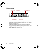
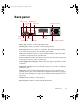
8506162.book Page 3 Wednesday, May 10, 2000 10:21 AM Back panel Mouse port Network port Parallel port Power connector Video port Keyboard Serial port port A Serial port B USB ports Expansion card slots Power supply fault LED Mouse port connects a PS/2-compatible mouse. Parallel port connects a printer or other parallel device. Network port lets you connect to a network. The adjacent indicator LEDs show LAN activity (yellow) and 100 Mbit speed (green).
8506162.book Page 4 Wednesday, May 10, 2000 10:21 AM Interior of system A B C D E F G N M L H J K I A Power supply provides power to the system components. B Expansion slot covers cover the spaces where you can install as many as two PCI expansion cards. C Riser card supports as many as two PCI expansion cards. D Intrusion switch logs a flag when the cover is removed to help prevent unauthorized access to the chassis. E System board see “System board” on page 6.
8506162.book Page 5 Wednesday, May 10, 2000 10:21 AM J Control panel supports the indicator LEDs and the buttons to control the Server operation. K Slimline CD drive plays data or audio CDs. L Secondary drive bay assembly supports the slimline CD drive and the legacy diskette drive. M Hot-plug backplane provides the control for the hot-plug drives. N Power distribution board controls power distribution from the power supply to the internal components.
8506162.
8506162.
8506162.book Page 8 Wednesday, May 10, 2000 10:21 AM Hot-plug backplane Back of the hot-plug backplane board SCSI connector Power connector Jumper block Front panel connector SCSI connector connects the SCSI cable from the RAID controller. Power connector connects the power cable from the power supply. Front panel connector carries signals from the backplane to the front panel.
8506162.book Page 9 Wednesday, May 10, 2000 10:21 AM Front panel board The front panel board supports the LEDs and buttons accessible from the front panel. The buttons and LEDs on the front panel board are shown and described below. Power LED Network activity LED Front panel connector System fault LED Power button Sleep button Reset button NMI switch Backplane connector ID0 ID1 ID2 ID3 Disk activity/fail LEDs Front panel connector connects the controls on the front panel with the system board.
8506162.book Page 10 Wednesday, May 10, 2000 10:21 AM Riser card The riser card includes a PCI bridge to support the two PCI expansion slots through the PCI expansion slot on the system board. PCI Slot 2 PCI Slot 1 Edge connector PCI expansion slots provide support for as many as two 32-bit, 33MHz PCI expansion cards. Slot 1 is the lower slot and slot 2 is the upper slot. Edge connector connects to the PCI slot closest to the processors.
8506162.book Page 11 Wednesday, May 10, 2000 10:21 AM 2 System Setup Setting up the server Use the instructions on the quick guide poster that came with the server to assemble the server. You can prepare a safer working environment before assembling the server by following these guidelines: ■ Obtain an adequately rated uninterruptible power supply (UPS). A UPS protects against AC line spikes, power interruptions, and other power fluctuations that may damage the server.
8506162.book Page 12 Wednesday, May 10, 2000 10:21 AM Starting the server Before you start the server for the first time, make sure: ■ If the power supply is autosensing, it will not have a voltagte selection switch and it automatically determines the voltage of the incoming power source. ■ All cables are firmly connected to the proper ports on the back panel of the server. Caution ■ Electricity can flow from connected peripherals into the system causing a shock.
8506162.book Page 13 Wednesday, May 10, 2000 10:21 AM Understanding the Power-On Self-Test When you turn on your server, the power-on self-test (POST) routine checks the system memory and components. To see this information on the screen, press ESC during POST. Press SPACEBAR to bypass the remaining memory count. The system displays an error message if POST finds any problems. Write down any error messages that you see.
8506162.book Page 14 Wednesday, May 10, 2000 10:21 AM To turn off the server in Windows NT: 1 Click Start, then select Shut down the computer?, then Shut Down. 2 Click OK. The operating system shuts down. When you see a message saying It is now safe to turn off your computer, turn off the server by pressing the power button. 3 Turn off the monitor and peripherals. 14 Caution When you turn the server off, some electric current still flows through it.
8506162.book Page 15 Wednesday, May 10, 2000 10:21 AM Resetting the server If your server does not respond to keyboard or mouse input, you may have to close programs that are not responding. If closing unresponsive programs does not restore your server to normal operation, you may have to reset the system. To close unresponsive programs and reset the server in Windows NT: 1 Press CTRL+ALT+DEL. A window opens that lets you close a program that is not responding.
8506162.
8506162.book Page 17 Wednesday, May 10, 2000 10:21 AM Case Access 3 Preventing static electricity discharge Before opening the server case, follow these precautions to prevent damage from static electricity. When opening your server case, always perform the following procedure. Caution Static electricity can permanently damage electronic components in your server. Prevent electrostatic damage to your server by following static electricity precautions every time you open your server case.
8506162.book Page 18 Wednesday, May 10, 2000 10:21 AM Opening the case Important All references to front, back, left, or right on the server are based on the server being in a normal, upright position, as viewed from the front. The only components that are accessible from the outside of the chassis are the front panel indicator lights. To access any of the removable media drives, the hot-plug drives, or the front panel buttons you must open the bezel.
8506162.book Page 19 Wednesday, May 10, 2000 10:21 AM Opening the bezel The bezel covers the removable media drives, the hot-plug drives, and the front panel controls. To access these components, you must open the bezel. To open the bezel: 1 Grip the bezel door and pull the door straight out away from the chassis. 2 Swing the door downward on its hinges so that it rests below the front of the system. Removing the top panel The top panel provides access to all of the internal components of the server.
8506162.book Page 20 Wednesday, May 10, 2000 10:21 AM 3 Remove the three screws from the top edge of the back panel. 4 Slide the top panel slightly to the back, disengaging the top edge of the panel from the top of the front panel. 5 Lift the panel out and away from the chassis. Closing the case Close the chassis as soon as you finish installing or removing components so that dust and dirt do not collect inside the server.
8506162.book Page 21 Wednesday, May 10, 2000 10:21 AM To replace the top panel: 1 Place the top panel on the top of the chassis approximately 3/4-inch back from the front of the server. 2 Slide the panel toward the front of the chassis 3/4-inch, securing it in place. The tabs on the front of the top panel slide under the lip of the front panel. 3 Replace the screws you removed earlier.
8506162.
8506162.book Page 23 Wednesday, May 10, 2000 10:21 AM Replacing and Adding Internal Devices 4 Drives There are several types of drives and similar devices that can be installed in the server. Preparing to replace or add a drive One 3.5-inch diskette drive, at least one 1-inch high 3.5-inch hot-plug hard drive, and one slimline CD drive are included with the server. You can add up to three additional 3.5-inch hot-plug drives for a total of four hot-plug drives.
8506162.book Page 24 Wednesday, May 10, 2000 10:21 AM Drive cabling information The system includes three different types of drive cables. Each drive cable is clearly labeled, indicating the cable type and showing which end to connect to the appropriate connector on the system board and which end to connect to the drive. ■ Use the diskette drive connector cable to connect the diskette drive. ■ Use the standard IDE connector cable to connect the CD drive.
8506162.book Page 25 Wednesday, May 10, 2000 10:21 AM 4 Remove the diskette drive tray by removing the two screws from the front panel. 5 Pull the tray out of the chassis. 6 Remove the drive from the tray by removing the four screws that secure the drive to the tray.
8506162.book Page 26 Wednesday, May 10, 2000 10:21 AM 7 If necessary, set any jumpers on the drive. (See your drive documentation for proper drive jumper settings and cable orientation.) 8 Attach the tray to the new drive by reinstalling the screws you removed in Step 6. 9 Replace the tray in the chassis using the screws you removed in Step 4 to secure the tray in position. 10 Connect the power and data cables, making sure the cables are in their original positions. 11 Close the case.
8506162.book Page 27 Wednesday, May 10, 2000 10:21 AM To replace a failed drive: 1 Before you remove the failed drive, use the appropriate software and utilities installed on the system to stop all activity on the failed drive. Instructions for using the software are provided by the software manufacturer. 2 Use the utilities or look at the drive indicator LEDs on the front panel to determine which drive needs to be replaced.
8506162.book Page 28 Wednesday, May 10, 2000 10:21 AM 6 Install the new drive in the carrier using the four screws you removed in Step 5. 7 Align the drive rails with the slots at the sides of the drive bay. Leave the retention lever in the open position. 8 Push the drive all of the way into the drive bay until the retention lever starts to close because of contact with the front of the chassis.
8506162.book Page 29 Wednesday, May 10, 2000 10:21 AM To install an additional hot-plug drive: 1 Remove the drive carrier from the drive bay by unclipping the retention lever and rotating the lever out away from the front of the system. 2 Continue pulling outward until the drive carrier is entirely out of the system. 3 Remove the four screws that secure the air baffles to the carrier, then remove the air baffles.
8506162.book Page 30 Wednesday, May 10, 2000 10:21 AM 4 Install the new drive in the carrier using the four screws you removed in Step 3. 5 Align the drive rails with the slots at the sides of the drive bay. Leave the retention lever in the open position. 6 Push the drive all of the way into the drive bay until the retention lever starts to close because of contact with the front of the chassis.
8506162.book Page 31 Wednesday, May 10, 2000 10:21 AM 3 For easier access to the CD drive, remove the cables to the diskette drive as described in “Replacing the diskette drive” on page 24. Note the orientation of the cables so you can replace them later. 4 Remove the power and data cables from the back of the CD drive, noting their locations and orientations. (You will reconnect these cables after you install the new drive.
8506162.book Page 32 Wednesday, May 10, 2000 10:21 AM 9 Reinstall the CD drive tray in the chassis and secure it with the three screws you removed in Step 5. 10 Connect the power and data cables, making sure the cables are in their original positions. (See your drive documentation for proper cable orientation.) 11 Reconnect the diskette drive cables using the instructions in “Replacing the diskette drive” on page 24. 12 Close the case. (See “Closing the case” on page 20.
8506162.book Page 33 Wednesday, May 10, 2000 10:21 AM Memory Four DIMM sockets on the system board support up to 2.0 Gigabytes (GB) of PC/100 SDRAM. Replacing memory The DRAM DIMMs supported by the system board conform to the following standards: ■ 128 MB, 256 MB, and 512 MB ECC DIMMs ■ PC/100-compliant, unbuffered, ECC SDRAM ■ 128 MB minimum system memory ■ 2.
8506162.book Page 34 Wednesday, May 10, 2000 10:21 AM 3 Pull open the socket clamps on each side of the DIMM socket, then lift the DIMM out of the socket. Store the DIMM in an anti-static container. 4 Insert the new DIMM into the socket, aligning the two notches in the DIMM with the two notches in the DIMM socket. 5 Gently press the DIMM into the socket until it is firmly seated. Inserting the DIMM automatically locks the socket clamps on each end of the DIMM. 6 Close the case.
8506162.book Page 35 Wednesday, May 10, 2000 10:21 AM Adding memory The DRAM DIMMs supported by the server board conform to the following standards: ■ 128 MB, 256 MB, and 512 MB ECC DIMMs ■ PC/100-compliant, unbuffered, ECC SDRAM ■ 128 MB minimum system memory ■ 2.0 GB maximum system memory When you select and install DIMMs, keep the following in mind: ■ Registered DIMMs should not be combined with unbuffered DIMMs ■ Memory should be added in order, from DIMM 1 to DIMM 4.
8506162.book Page 36 Wednesday, May 10, 2000 10:21 AM 5 Gently press the DIMM into the socket until it is firmly seated. Inserting the DIMM automatically locks the socket clamps on each end of the DIMM. 6 Close the case. (See “Closing the case” on page 20.) 7 Reconnect the peripherals and the power cord, then turn on the system.
8506162.book Page 37 Wednesday, May 10, 2000 10:21 AM Processors The system is compatible with the Intel® Pentium® III 600 MHz and faster processors with 100 MHz front-side bus (FSB). As many as two processors may be installed in the system. You do not need to install additional voltage regulator modules (VRMs), because the VRMs for both processors are built into the system board. Replacing a processor When replacing a processor, order a processor upgrade kit from Gateway.
8506162.book Page 38 Wednesday, May 10, 2000 10:21 AM 4 Place the head of a flat-bladed screwdriver between the processor module and the tab on the side of one of the processor retention brackets that hold the processor to be removed. 5 Push the handle of the screwdriver toward the processor. When the tab that locks the processor in place opens, lift up slightly on the side of the processor. 6 Repeat the previous two steps for the other side of the processor.
8506162.book Page 39 Wednesday, May 10, 2000 10:21 AM 7 Pull the processor up and out of the slot. 8 If the heatseink is separate, attach it to the processor.
8506162.book Page 40 Wednesday, May 10, 2000 10:21 AM 9 Align the new processor with the processor slot (note that the processor slot is keyed so the processor can only be installed one way) and press firmly to install it. 10 Reconnect the processor fan cable to the processor fan connector on the system board. 11 Close the case. (See “Closing the case” on page 20.) 12 Reconnect the power cord and all other cords you removed, then turn on the system.
8506162.book Page 41 Wednesday, May 10, 2000 10:21 AM When adding a second processor order a processor upgrade kit from Gateway. The kit includes the processor, a fansink or heatsink, and a disposable grounding wrist strap. Caution A heatsink or fansink must be installed on each processor. Installing a processor without a heatsink or fansink could result in damage to, or failure of, the processor.
8506162.book Page 42 Wednesday, May 10, 2000 10:21 AM 5 Align the new processor with the processor slot. Note that the processor slot is keyed so the processor can only be installed one way. Press it firmly to install it. 6 Connect the processor fan cable to the secondary processor fan connector on the system board (See “System board” on page 6 for location). 7 Close the case. (See “Closing the case” on page 20.) 8 Reconnect the power cord and all other cords you removed, then turn on the system.
8506162.book Page 43 Wednesday, May 10, 2000 10:21 AM Replacing the battery The battery provides power for the system real-time clock and CMOS memory, which holds the system configuration information. If your battery is failing you may notice the server clock slowing down and giving you the incorrect time. Open the BIOS Setup utility and write down all the values in the various menus before replacing the battery. Replacing the battery resets the BIOS Setup utility to its default values.
8506162.book Page 44 Wednesday, May 10, 2000 10:21 AM 3 Turn off the server, disconnect the power cord and all external peripheral devices. 4 Open the case by following the instructions on page 18. (See “Preventing static electricity discharge” on page 17.) 5 Locate the battery on the system board (see “System board” on page 6). The battery is circular and has the positive pole mark (+) on the top.
8506162.book Page 45 Wednesday, May 10, 2000 10:21 AM ■ Turn off the server, remove the cover, and make sure that all cables inside the case are attached securely. Also, make sure that the colored cable edges are aligned correctly and that the connectors did not miss any pins. Disconnect and reconnect the cables. Close the case as described in “Closing the case” on page 20, reconnect the modem and power cords, then turn on the server.
8506162.book Page 46 Wednesday, May 10, 2000 10:21 AM Expansion cards The server has two expansion slots on the riser card that can be used for a variety of expansion cards. These slots support 32-bit, 33 MHz PCI cards. Both slots will hold full-length cards. The expansion slots on the system board are not used. Replacing an expansion card You must install an expansion card in slot 1 before you can install an expansion card in slot 2.
8506162.book Page 47 Wednesday, May 10, 2000 10:21 AM 6 If the card is a full length card, slide the card guide behind the fans by pushing out the lever and sliding the card guide to the side until it locks into place, then remove the expansion card from the system. 7 If the replacement riser card has an ISA retainer (a plastic piece on the end of the card), remove the ISA retainer, then install the expansion card in the chassis. PCI slot 1 is the bottom slot and PCI slot 2 is the top slot.
8506162.book Page 48 Wednesday, May 10, 2000 10:21 AM 8 Replace the expansion slot cover bracket and tighten the thumbscrew. 9 Replace the card guide by sliding it back to its original position until it clicks in place. Make sure the end of the card is in the right slot in the card guide. 10 Connect any cables to the card (see card documentation for proper cable orientation). 11 Close the case. (See “Closing the case” on page 20.) 12 Reconnect the peripherals and the power cord, then turn on the system.
8506162.book Page 49 Wednesday, May 10, 2000 10:21 AM 4 Locate an available slot and remove the slot cover by removing the thumbscrew on the slot cover bracket, then remove the slot cover bracket. PCI slot 1 is the bottom slot and PCI slot 2 is the top slot. 5 Pull out the slot cover.
8506162.book Page 50 Wednesday, May 10, 2000 10:21 AM 6 If the card is a full-length expansion card, press the lever to release the card guide and slide the card guide to the side. 7 Insert the bottom edge of the expansion card (the keyed edge with the contacts) into the slot on the riser card and push in firmly to seat the card.
8506162.book Page 51 Wednesday, May 10, 2000 10:21 AM 8 Replace the expansion slot cover bracket and tighten the thumbscrew. 9 Replace the card guide by sliding it back to its original position until it clicks in place. Make sure the end of the card is in the right slot in the card guide. 10 Connect any cables to the card (see card documentation for proper cable orientation). 11 Close the case. (See “Closing the case” on page 20.) 12 Reconnect the peripherals and the power cord, then turn on the system.
8506162.book Page 52 Wednesday, May 10, 2000 10:21 AM 3 Open the power supply cover by removing the two screws that secure it in place, then swing the cover up. 4 Holding the sides of the power supply, push it out through the back panel of the chassis. 5 Insert the new power supply through the back panel, making sure that the connectors on the power supply seat firmly in the connectors on the power distribution board. 6 Close the power supply cover and replace the screws you removed in Step 3.
8506162.book Page 53 Wednesday, May 10, 2000 10:21 AM Replacing the power distribution board The power distribution board is beside the power supply and serves to separate the power produced by the power supply into the voltages needed by the various internal components. To replace the power distribution board: 1 Turn off the system and disconnect the power cord and external peripherals. 2 Open the case. (See “Opening the case” on page 18 and “Preventing static electricity discharge” on page 17.
8506162.book Page 54 Wednesday, May 10, 2000 10:21 AM 6 Place the replacement board in the chassis in the same orientation as the original board, then replace the four screws you removed in Step 5. 7 Reconnect the cables to the board at the same locations and in the same orientations as they were originally connected. 8 Replace the power supply. 9 Close the case. (See “Closing the case” on page 20.) 10 Reconnect the power cord and external peripherals, then turn on the system.
8506162.book Page 55 Wednesday, May 10, 2000 10:21 AM 4 Pull out on the tabs on both sides of the fan and lift the fan out of the fan assembly. Tabs 5 Insert the new fan into the fan assembly. Make sure the direction of rotation and airflow match the direction and airflow of the fan you removed. 6 Plug the fan connector into the connector on the system board. Fan 1 plugs into connector J1J1 and fan 2 plugs into connector J1G6. 7 Close the case. (See “Closing the case” on page 20.
8506162.book Page 56 Wednesday, May 10, 2000 10:21 AM Replacing the front panel board The front panel board is mounted on the front of the chassis, inside the front panel. To replace the front panel board: 1 Turn off the system and disconnect the power cord and all external peripherals. 2 Open the case. (See “Opening the case” on page 18 and “Preventing static electricity discharge” on page 17.) 3 Disconnect all cables from the front panel board.
8506162.book Page 57 Wednesday, May 10, 2000 10:21 AM Replacing the hot-plug backplane The four drive hot-plug backplane is at the back of the hot-plug drive cage. The backplane supports as many as four hot-swappable LVD SCSI drives. To replace the hot-plug backplane: 1 Turn off the system and disconnect the power cord and all external peripheral devices. 2 Open the case. (See “Opening the case” on page 18 and “Preventing static electricity discharge” on page 17.
8506162.book Page 58 Wednesday, May 10, 2000 10:21 AM 7 Remove the six screws that secure the backplane to the hot-plug drive bay and remove the backplane. Screw Screw Screw Screw Screw Screw 8 Set any jumpers on the new backplane for your configuration. 9 Secure the new backplane to the back of the hot-plug drive bay with the six screws you removed in Step 7.
8506162.book Page 59 Wednesday, May 10, 2000 10:21 AM 10 Replace the drive bay in the chassis. Make sure the tabs on the bottom of the drive bay fit into the slots on the bottom of the chassis and the drive bay sits flat on the bottom of the chassis. 11 Replace the six screws you removed in Step 5. 12 Reconnect all cables on the backplane to the correct connectors. 13 Replace all hot-plug drives. Make sure that you replace them in the same slots that they were in before you removed them.
8506162.book Page 60 Wednesday, May 10, 2000 10:21 AM Replacing the system board The system board integrates the other elements of the system, such as the processor, memory, storage, networking, and communications. To replace the system board: 1 Turn off the system and disconnect the power cord and all external peripheral devices. 2 Open the case. (See “Opening the case” on page 18 and “Preventing static electricity discharge” on page 17.) 3 Remove all expansion cards from the system.
8506162.book Page 61 Wednesday, May 10, 2000 10:21 AM 6 Remove the three screws that secure the fan assembly to the chassis, then lift the fan assembly up and place it on the hot-plug drive bay. Screw Screw Screw 7 Remove any processors and DIMMs that you will install in the new system board. (See “Replacing memory” on page 33 and “Replacing a processor” on page 37.
8506162.book Page 62 Wednesday, May 10, 2000 10:21 AM 8 Remove the eleven screws that secure the system board to the chassis, then lift the system board out of the chassis. 9 Remove the new system board from its anti-static bag and set any jumpers that you may need to set for your configuration. See “System board” on page 6 and “Setting the system board jumpers” on page 68.
8506162.book Page 63 Wednesday, May 10, 2000 10:21 AM 10 Place the new system board in the chassis. Make sure the two standoffs with shoulders fit into the matching holes in the system board. 11 Replace the eleven screws you removed in Step 8. 12 Install the DIMM(s) and processor(s) in the new system board. (See “Replacing memory” on page 33 and “Replacing a processor” on page 37.) 13 Replace the fan assembly using the three screws you removed in Step 6.
8506162.book Page 64 Wednesday, May 10, 2000 10:21 AM 16 Replace any expansion cards you removed from the system in Step 3. (See “Replacing an expansion card” on page 46.) 17 Close the case. (See “Closing the case” on page 20.) 18 Reconnect all peripherals and the power cord, then turn on the system.
8506162.book Page 65 Wednesday, May 10, 2000 10:21 AM 5 Using the BIOS Setup Utility About the BIOS Setup utility The server BIOS has a built-in setup utility that lets you configure several basic system characteristics. The settings are stored in battery-backed RAM and are retained even when the power is off. Enter the BIOS Setup utility by restarting the server, then pressing F2 when prompted during the startup process. The Main BIOS Setup utility screen opens.
8506162.book Page 66 Wednesday, May 10, 2000 10:21 AM As you select items on the Main menu or in submenus, you see specific information related to the current selection in the Item Specific Help box. The command bar shows the keystrokes necessary to access help, navigate through the menus, and perform other functions. ■ F1 opens the Help screen, providing general help for using the BIOS Setup utility. ■ The ↑ (up arrow) and ↓ (down arrow) keys select items in the menu.
8506162.book Page 67 Wednesday, May 10, 2000 10:21 AM Updating the BIOS If you need a new version of the BIOS, you can download the BIOS update from the technical support area on the Gateway Web site (www.gatewayatwork.com) and install the new version from a diskette.
8506162.book Page 68 Wednesday, May 10, 2000 10:21 AM Setting the system board jumpers The system board has three jumpers. Each of these jumpers has a specific function described in the sections below. The CMOS Clear jumper The CMOS Clear jumper on the system board (pins 1 through 3 of jumper J2J1) lets you clear all BIOS Setup settings. (See the figure on page 6 for the location of the jumper.) The following table shows the settings required to perform this task.
8506162.book Page 69 Wednesday, May 10, 2000 10:21 AM The following table shows the settings required to perform this task. Make sure you turn off the server and unplug the power cord before moving the jumper. Mode Jumper Setting Protect Action When Set Normal operation (default) Pins 5-6 Clear Clears all passwords at bootup Pins 6-7 Caution Moving the jumper while the power is on can damage the server. Always turn off the server and unplug the power cord before moving the jumper.
8506162.book Page 70 Wednesday, May 10, 2000 10:21 AM BIOS Boot Block Write Enable jumper The BIOS Boot Block Write Enable jumper on the system board (pins 13 through 15 of jumper J2J1) lets you update the BIOS boot block. (See the figure on page 6 for the location of the jumper.) Caution Incorrect programming of the boot block may make the system unbootable. The following table shows the settings required to perform this function.
8506162.book Page 71 Wednesday, May 10, 2000 10:21 AM The following table shows the settings required to allow programming of the BMC boot block. Make sure you turn off the server and unplug the power cord before moving the jumper. Mode Jumper Setting Normal Pins 1-2 Writes enabled Pins 2-3 Caution Action When Set BMC boot block is write protected (default) Allows BMC boot block to be programmed through the correct utilities. Moving the jumper while the power is on can damage the server.
8506162.book Page 72 Wednesday, May 10, 2000 10:21 AM Intrusion Detection Enable jumper The Intrusion Detection Enable jumper on the system board (pins 5 through 7 on jumper J3J1) lets you enable intrusion detection. (See the figure on page 6 for the location of the jumper.) The following table shows the settings required to enable intrusion detection. Make sure you turn off the server and unplug the power cord before moving the jumper.
8506162.book Page 73 Wednesday, May 10, 2000 10:21 AM The following table shows the settings required to let you update the BMC firmware. Make sure you turn off the server and unplug the power cord before moving the jumper. Mode Jumper Setting Normal Action When Set Normal boot (default) Pins 9-10 Update BMC System updates BMC Pins 10-11 Caution Moving the jumper while the power is on can damage the server. Always turn off the server and unplug the power cord before moving the jumper.
8506162.
8506162.book Page 75 Wednesday, May 10, 2000 10:21 AM Managing the Server 6 Avoiding power source problems Surge suppressors, line conditioners, and uninterruptible power supplies can help protect the server against power source problems. Surge suppressors During a power surge, the voltage level of electricity coming into the server can increase far above normal levels and cause data loss or system damage.
8506162.book Page 76 Wednesday, May 10, 2000 10:21 AM Line conditioners A line conditioner protects the server from the small fluctuations in voltage from an electrical supply. Most systems can handle this variation (line noise) without problems. However, some electrical sources include more line noise than normal. Line noise can also be a problem if the server is located near, or shares a circuit with, a device that causes electromagnetic interference, such as a television or a motor.
8506162.book Page 77 Wednesday, May 10, 2000 10:21 AM Use Check Disk from once a week to once a month, depending on how often you use the server. Also use Check Disk if you have any hard drive problems. To use Check Disk: 1 Double-click the My Computer icon. The My Computer window opens. 2 Right-click the drive you want to check. 3 Select Properties. The drive’s properties window opens. 4 Click the Tools tab. 5 At Error-checking, click Check Now. The Check Disk window opens.
06162.book Page 78 Wednesday, May 10, 2000 10:21 AM Backing up files Regularly backing up your files protects you from losing data and lets you keep fewer files on your hard drive. Back up old files to a large capacity disk drive or tape drive and delete the files from your hard drive. You can use the software that came with your tape backup drive or your large capacity disk drive to back up the files. You can also back up files by running the Backup utility that came with your operating system.
8506162.book Page 79 Wednesday, May 10, 2000 10:21 AM Deleting temporary Internet files As you visit Web sites, your browser stores temporary Internet files on your hard drive in a memory cache and a disk cache. Files in the memory cache are removed when you turn off your server. Files are saved in the disk cache until the space designated for the cache is full. See your browser’s Help files for instructions on emptying the disk cache.
8506162.book Page 80 Wednesday, May 10, 2000 10:21 AM Protecting the server against viruses A virus is a program that attaches itself to a program or data file on a computer, then spreads from one computer to another. Viruses can damage data, cause computers to malfunction, and can display annoying or offensive messages. Some viruses can go unnoticed for long periods of time because they are activated by a certain date or time.
8506162.book Page 81 Wednesday, May 10, 2000 10:21 AM System administration and control The server has three server-management tools included to enable administration and control of Windows NT environments. These tools are Intel® Server Control (ISC), ManageX Event Manager, and the Direct Platform Control (DPC) Console. Intel Server Control (ISC) Using a graphical user interface, ISC can locally or remotely provide real-time monitoring and alerting for server hardware sensors.
8506162.book Page 82 Wednesday, May 10, 2000 10:21 AM Direct Platform Control (DPC) Console The Direct Platform Control (DPC) Console provides remote emergency management of servers. The DPC Console is independent of the server operating system and provides a means to remotely diagnose problems or verify the state of the server. It will also turn the server on or off. You can find additional information about DPC Console under Documentation on the Server Companion CD which came with the server.
8506162.book Page 83 Wednesday, May 10, 2000 10:21 AM Using passwords If you set and enable a user password but not an administrator password, enter the user password to boot the system with limited BIOS Setup access.
8506162.book Page 84 Wednesday, May 10, 2000 10:21 AM Summary of software security features The following table lists the software security features and describes what protection each offers. In general, to enable or set the features listed here, you must run the BIOS Setup utility and go to the Security Menu. The table also refers to other Setup utility menus. For more information on setting the security features, see “About the BIOS Setup utility” on page 65.
8506162.book Page 85 Wednesday, May 10, 2000 10:21 AM Feature Description Control access to the system other than BIOS Setup (set user password) To control access to the system, set a user password and enable the Password on Boot option using the BIOS Setup utility. Once set, passwords can be disabled by deleting the password or by changing the Password Clear jumper. See “Password Clear jumper” on page 68. Boot without keyboard The system can boot with or without a keyboard.
8506162.book Page 86 Wednesday, May 10, 2000 10:21 AM System recovery Take precautions that allow you to recover damaged files and recover your system in the event that your hard drive is damaged, or if your BIOS or system files get corrupted. Creating a startup diskette If your server hard drive is damaged, you may not be able to start the server from the hard drive. A startup diskette is a bootable diskette that lets you start the server and attempt to fix the problem.
8506162.book Page 87 Wednesday, May 10, 2000 10:21 AM 7 Troubleshooting Introduction If the server does not operate correctly, re-read the instructions for the procedures you have performed. If an error occurs within an application, refer to the documentation supplied with the software. This section identifies solutions to some possible problems. Troubleshooting checklist Before turning on the system, make sure that: ■ The power cord is connected to the AC power-in connector and an AC outlet.
8506162.book Page 88 Wednesday, May 10, 2000 10:21 AM Troubleshooting guidelines As you troubleshoot the server, keep the following guidelines in mind: ■ Never remove the chassis cover while the server is turned on. ■ Do not attempt to open the monitor; it is extremely dangerous. Even if the power is disconnected, stored energy in the components can be dangerous. ■ If a peripheral does not work, make sure that all connections are secure.
8506162.book Page 89 Wednesday, May 10, 2000 10:21 AM Probable cause Solution The CD drive cables are not installed correctly Open the system, then make sure all cables between the IDE controller and the CD drive are correctly connected. The CD drive may be defective Replace the CD drive. Hard drive problems The system does not recognize a SCSI drive Probable cause Solution SCSI hot-plug drive is not seated correctly Open the system and reseat the hot-plug drive(s).
8506162.book Page 90 Wednesday, May 10, 2000 10:21 AM Probable cause Solution A memory chip is faulty Replace the card with the faulty chip. Third-party diagnostic programs can help determine which chip or memory segment is failing. The system does not recognize a new or second processor Probable cause Solution The processor was installed incorrectly Check the installation. Make sure that the processor is fully seated in its socket.
8506162.book Page 91 Wednesday, May 10, 2000 10:21 AM Peripheral/Adapter problems The system does not recognize a SCSI device Probable cause Solution The device needs to be added as new hardware From the Control Panel window (Start | Settings | Control Panel), double-click Add New Hardware. Follow the on-screen instructions for adding the device. The SCSI ID may be invalid Assign an available SCSI ID to the device.
8506162.book Page 92 Wednesday, May 10, 2000 10:21 AM Probable cause Solution The diskette is corrupted Run CheckDisk on the diskette. If errors are detected and corrected, try accessing the diskette again. The diskette drive LED illuminates continuously Probable cause Solution The diskette is corrupted Remove the diskette from the drive. If the light remains on, try restarting the system.
8506162.book Page 93 Wednesday, May 10, 2000 10:21 AM Probable cause Solution The printer is not plugged in Make sure that the power cable is plugged into a live power source. The printer is defective Try another printer, if one is available. The printer is turned on but will not print Probable cause Solution The printer is not connected to the system Make sure the data cable between the printer and the system is properly connected. Make sure that it is connected to the proper port.
8506162.book Page 94 Wednesday, May 10, 2000 10:21 AM Probable cause Solution Power supply alarm buzzes and power supply status LED blinks indicating a failed power supply module Replace the indicated power supply module. (You can turn off the audible alarm by inserting an appropriate tool into the port on the front panel and pressing the switch.) Power supply alarm buzzes and both power supply status LEDs blink, indicating a failed common component Replace the entire power supply housing.
8506162.book Page 95 Wednesday, May 10, 2000 10:21 AM The mouse does not work Probable cause Solution Mouse is locked out when the password is set Enter the password. The mouse is not plugged in or connected properly Make sure that the cable is plugged in correctly. The mouse driver did not load when the system started Load the appropriate mouse driver manually or contact technical support. The mouse is defective Try a mouse that you know is working.
8506162.book Page 96 Wednesday, May 10, 2000 10:21 AM Probable cause Solution The video card is not seated correctly Open the system and reseat the video card. The server board may have a built-in video adapter, so there may not be a video adapter to remove and replace. The video card is not compatible with the system Check the documentation or technical support to make sure that the video card is compatible with the system. If not, obtain a compatible video card.
8506162.book Page 97 Wednesday, May 10, 2000 10:21 AM Probable cause Solution The display setup is incorrect In the Control Panel window (Start | Settings | Control Panel), double-click Display and check the settings. The correct video type should be selected, along with a supported resolution. Check your monitor and video controller documentation for details. The video card has failed Try another video card.
8506162.book Page 98 Wednesday, May 10, 2000 10:21 AM Error message Solutions Bad command or file name Make certain you entered the right command. Verify the specified drive, then try it again. If you are trying to exit MS-DOS to return to Windows, type exit, then press ENTER. Base memory [xxx] expansion This is an informational message only. No action is required. Checking RAM on disk controller Your BIOS configuration is incorrect.
8506162.book Page 99 Wednesday, May 10, 2000 10:21 AM Error message Solutions Insert bootable media device See “The system does not recognize a SCSI drive” on page 89 for a possible solution. Backup your files as soon as possible. Insufficient disk space Check the free space on the disk volume. If the volume is full or almost full, remove unnecessary files. Invalid configuration information Open the BIOS Setup utility, then make sure the settings are correct.
8506162.book Page 100 Wednesday, May 10, 2000 10:21 AM Error message Solutions Printer is out of paper Add paper to the printer. Make sure that the printer is online. Required parameter missing Make sure that you entered the right command. If you are trying to exit MS-DOS to return to Windows, type exit, then press ENTER. Syntax error Make sure that you entered the right command. If you are trying to exit MS-DOS to return to Windows, type exit, then press ENTER.
8506162.book Page 101 Wednesday, May 10, 2000 10:21 AM Safety, Regulatory, and Notices A The Gateway 7250R Server originally shipped with a Class A rating according to FCC rules part 15. Later modifications may have improved the rating to Class B. To check the rating of the system as shipped to you, check the FCC label at the back of the chassis for the rating.
8506162.book Page 102 Wednesday, May 10, 2000 10:21 AM ■ Openings in the computer case are provided for ventilation. Do not block or cover these openings. Make sure you provide adequate space, at least 6 inches (15 cm), around the system for ventilation when you set up your work area. Never insert objects of any kind into the computer ventilation openings. ■ Some products are equipped with a three-wire power cord to make sure that the product is properly grounded when in use.
8506162.book Page 103 Wednesday, May 10, 2000 10:21 AM Warnings WARNING: English (US) AVERTISSEMENT: Français WARNUNG: Deutsch AVVERTENZA: Italiano ADVERTENCIAS: Español The power supply in this product contains no user-serviceable parts. There may be more than one supply in this product. Refer servicing only to qualified personnel. Le bloc d’alimentation de ce produit ne contient aucune pièce pouvant être réparée par l'utilisateur. Ce produit peut contenir plus d'un bloc d'alimentation.
8506162.book Page 104 Wednesday, May 10, 2000 10:21 AM 104 WARNING: English (US) AVERTISSEMENT: Français WARNUNG: Deutsch AVVERTENZA: Italiano ADVERTENCIAS: Español After you have completed the six SAFETY steps above, you can remove the system covers. To do this: 1 Unlock and remove the padlock from the back of the system if a padlock has been installed. 2 Remove and save all screws from the covers. 3 Remove the covers.
8506162.book Page 105 Wednesday, May 10, 2000 10:21 AM WARNING: English (US) AVERTISSEMENT: Français WARNUNG: Deutsch AVVERTENZA: Italiano ADVERTENCIAS: Español The system is designed to operate in a typical office environment. Choose a site that is: ■ Clean and free of airborne particles (other than normal room dust). ■ Well ventilated and away from sources of heat including direct sunlight. ■ Away from sources of vibration or physical shock.
8506162.book Page 106 Wednesday, May 10, 2000 10:21 AM Regulatory compliance statements Rack Mounting If rack mounted units are installed in a closed or multi-unit rack assembly, they may require further evaluation by Certification Agencies. The following items must be considered: ■ The ambient within the rack may be greater than room ambient. Installation should be such that the amount of airflow required for safe operation is not compromised.
8506162.book Page 107 Wednesday, May 10, 2000 10:21 AM FCC Part 68 (applicable to products fitted with USA modems) Your modem complies with Part 68 of the Federal Communications Commission (FCC) rules. On the computer or modem card is a label that contains the FCC registration number and Ringer Equivalence Number (REN) for this device. If requested, this information must be provided to the telephone company. An FCC compliant telephone line cord with a modular plug is required for use with this device.
8506162.book Page 108 Wednesday, May 10, 2000 10:21 AM DOC Notice (for products fitted with an IC-compliant modem) The Industry Canada label identifies certified equipment. This certification means that the equipment meets certain telecommunications network protective, operation, and safety requirements. The Department does not guarantee the equipment will operate to the users’ satisfaction.
8506162.book Page 109 Wednesday, May 10, 2000 10:21 AM European Telecommunication Information (for products fitted with EU approved modems) Marking by the symbol indicates compliance of this equipment to the Telecom Terminal Equipment and Satellite Earth Stations Directive 98/13/EEC.
8506162.book Page 110 Wednesday, May 10, 2000 10:21 AM Australia and New Zealand users EMI statement This device has been tested and found to comply with the limits for a Class A digital device, pursuant to the Australian/New Zealand standard AS/NZS 3548 set out by the Australian Communications Authority and Radio Spectrum Management Agency.
8506162.book Page 111 Wednesday, May 10, 2000 10:21 AM Laser safety statement All Gateway systems equipped with CD and DVD drives comply with the appropriate safety standards, including IEC 825. The laser devices in these components are classified as “Class 1 Laser Products” under a US Department of Health and Human Services (DHHS) Radiation Performance Standard. Should the unit ever need servicing contact an authorized service location.
8506162.
8506162.book Page 113 Wednesday, May 10, 2000 10:21 AM Notices Copyright © 2000 Gateway, Inc. All Rights Reserved 4545 Town Centre Court San Diego, CA 92121 USA All rights reserved This publication is protected by copyright and all rights are reserved. No part of it may be reproduced or transmitted by any means or in any form, without prior consent in writing from Gateway. The information in this manual has been carefully checked and is believed to be accurate. However, changes are made periodically.
8506162.
8506162.book Page 115 Wednesday, May 10, 2000 10:21 AM B System Specifications The following specifications are for the standard configuration. The server may contain optional equipment. All specifications are subject to change. Case size 18.9 in. (480 mm) x 24.1 in. (612 mm) x 3.46 in. (88 mm) Processors As many as two Intel® Pentium III™ processors operating at 600 MHz and faster Cache 256K on processor RAM Four DIMM sockets support up to 2.
8506162.book Page 116 Wednesday, May 10, 2000 10:21 AM Environmental specifications The following specifications identify maximum environmental conditions. At no time should the server run under conditions which violate these specifications. Temperature, operating 5° to 35° Celsius or 44° to 95° Fahrenheit. Humidity, operating 20% to 80% Altitude -200 feet to 10,000 feet Voltage, AC input 90 to 135 VAC, 180 to 255 VAC Frequency 47 to 63 Hz Certification FCC Class A, UL, CUL, CAN/CSA STD C22.
8506162.
8506162.
8506162.book Page 119 Wednesday, May 10, 2000 10:21 AM Memory map Address Range (hex) Amount Function 0 to 07FFFFh 640 KB DOS region, base system memory 0A0000h to 0BFFFFh 128 KB Video or SMM memory 0C0000h and 0DFFFFh 128 KB Expansion card BIOS and buffer area 0F0000h to 0FFFFFh 128 KB System BIOS 0E0000h to 0EFFFFh 64 KB Extended system BIOS FC000000h to FFFFFFFFh 64 MB PCI memory space Interrupts The following table suggests a logical interrupt mapping of interrupt sources.
8506162.
8506162.
8506162.
8506162.
8506162.
8506162.
8506162.
8506162.
A MAN US 7250R SYS RACK GDE R0 4/00 7250R Server System Manual