8508366.
8508366.book Page ii Tuesday, October 23, 2001 11:29 AM Notices Copyright © 2001 Gateway, Inc. All Rights Reserved 4545 Town Centre Court San Diego, CA 92121 USA All Rights Reserved This publication is protected by copyright and all rights are reserved. No part of it may be reproduced or transmitted by any means or in any form, without prior consent in writing from Gateway. The information in this manual has been carefully checked and is believed to be accurate. However, changes are made periodically.
8508366.book Page iii Tuesday, October 23, 2001 11:29 AM Contents Preface . . . . . . . . . . . . . . . . . . . . . . . . . . . . . . . . . . . . . . . . . . . . . . . . . . . . . . . . . . . . . vii Conventions used in this manual . . . . . . . . . . . . . . . . . . . . . . . . . . . . . . . . . . . . . . .vii Getting additional information . . . . . . . . . . . . . . . . . . . . . . . . . . . . . . . . . . . . . . . . . viii 1 System Features . . . . . . . . . . . . . . . . . . . . . . . . . . . . . . .
8508366.book Page iv Tuesday, October 23, 2001 11:29 AM Replacing the diskette drive . . . . . . . . . . . . . . . . . . . . . . . . . . . . . . . . . . . . . . . .31 Replacing an optional drive . . . . . . . . . . . . . . . . . . . . . . . . . . . . . . . . . . . . . . . .33 Installing a 3.5-inch drive in a 5.25-inch drive bay . . . . . . . . . . . . . . . . . . . . . .35 Replacing a hot-plug drive . . . . . . . . . . . . . . . . . . . . . . . . . . . . . . . . . . . . . . . . .
8508366.book Page v Tuesday, October 23, 2001 11:29 AM Using your Server Companion CD . . . . . . . . . . . . . . . . . . . . . . . . . . . . . . . . . 101 7 Cleaning the Server . . . . . . . . . . . . . . . . . . . . . . . . . . . . . . . . . . . . . . . . . . . 103 Cleaning Cleaning Cleaning Cleaning the the the the mouse . . . . . . . . . . . . . . . . . . . . . . . . . . . . . . . . . . . . . . . . . . . . . . . keyboard . . . . . . . . . . . . . . . . . . . . . . . . . . . . . . . . . . . . . . . .
8508366.
8508366.book Page vii Tuesday, October 23, 2001 11:29 AM Preface Conventions used in this manual Throughout this manual, you will see the following conventions: Convention Description ENTER Keyboard key names are printed in small capitals. CTRL+ALT+DEL A plus sign means to press the keys at the same time. Setup Commands to be entered, options to select, and messages that appear on your monitor are printed in bold. User’s Guide Names of publications are printed in italic.
508366.book Page viii Tuesday, October 23, 2001 11:29 AM Getting additional information Log on to the Technical Support area at www.gatewayatwork.com to find information about your system or other Gateway products.
8508366.book Page 1 Tuesday, October 23, 2001 11:29 AM 1 System Features Standard features ■ As many as two Pentium® III (FC-PGA Socket 370) processors with 133 MHz Front Side Bus (FSB) ■ Four Dual Inline Memory Module (DIMM) sockets, that support up to 2 GB of PC133 Synchronous Dynamic Random Access Memory (SDRAM) ■ RCC Champion LE 3.
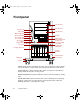
8508366.book Page 2 Tuesday, October 23, 2001 11:29 AM Front panel 5.25” drive bay 5.25” drive bay Chassis lock Power LED 5.
8508366.book Page 3 Tuesday, October 23, 2001 11:29 AM PS 1 status LED glows green when the first power supply module in the redundant power supply is installed and working correctly. It flashes green if the power supply module fails or one of its power levels goes out of bounds. If the power supply module is not installed, this LED is off. PS 2 status LED glows green when the second power supply module in the redundant power supply is installed and working correctly.
8508366.
8508366.book Page 5 Tuesday, October 23, 2001 11:29 AM Power supply cable clamp secures the power supply cords so that they are not accidentally pulled from the power supply. Keyboard port connects to a PS/2-compatible keyboard. USB ports connect to external Plug-and-Play devices, such as printers, that are automatically configured when they are plugged into the server through one of these ports. USB keyboards and mice are not supported. Serial ports (2) connect to serial devices.
8508366.book Page 6 Tuesday, October 23, 2001 11:29 AM Interior of system Power supply Power supply fans 5.25-inch drive bays N+1 power supply alarm board 3.25-inch drive bays Hot-plug bays (Hot-plug cage) Back panel fan System board System Drive board tray cage fan SCSI backplane Power supply provides power to the system components. The redundant power supply provides hot-plug capability and fault tolerance. Power supply fans provide cooling for the redundant power supply modules. 5.
8508366.book Page 7 Tuesday, October 23, 2001 11:29 AM SCSI backplane provides the control for the hot-plug drives. Drive cage fan provides cooling for the hot-plug drives and other internal components. System board tray supports the system board and makes it easier to remove and install. System board (See “System board” on page 8.) Back panel fan provides cooling for system board components and additional cooling for the power supply.
8508366.
8508366.
8508366.book Page 10 Tuesday, October 23, 2001 11:29 AM SCSI backplane board Back side JP5: Delay start jumper Power connector SCSI connector JP6: Termination jumper JP5: Delay start jumper controls the spin-up sequence of the drives attached to the backplane. If you leave the delay start jumper on (enabled - default), the drives spin up one at a time in order of their SCSI ID.
8508366.book Page 11 Tuesday, October 23, 2001 11:29 AM Front side Reserved LED (6) Drive activity LED (6) SCA SCSI drive connectors (6) SCSI ID 2 SCSI ID 5 SCSI ID 1 SCSI ID 4 SCSI ID 0 SCSI ID 3 Reserved LED (6) reserved for future use. Drive activity LED (6) flashes green when the drive is actively reading or writing data. SCA SCSI drive connectors (6) provide points of connection for six SCA SCSI drives.
8508366.book Page 12 Tuesday, October 23, 2001 11:29 AM Front panel board The front panel board supports the LEDs and buttons accessible from the front panel. The buttons and LEDs on the front panel board are shown and described below.
8508366.book Page 13 Tuesday, October 23, 2001 11:29 AM PS 2 status LED glows green when the second power supply module in the redundant power supply is installed and working correctly. It flashes green if the power supply module fails or one of its power levels goes out of bounds. If the power supply module is not installed, this LED is off. System reset button lets you reset the server if it has become nonresponsive. Power button turns the server on and off.
8508366.
8508366.book Page 15 Tuesday, October 23, 2001 11:29 AM 2 System Setup Setting up the server Use the instructions on the quick guide poster that came with the server to assemble the server. You can prepare a safer working environment before assembling the server by following these guidelines: ■ Use a clean, flat, and stable surface for the server. Allow at least 12 inches at the rear of the server for cabling and air circulation. ■ Obtain an adequately rated uninterruptible power supply (UPS).
8508366.book Page 16 Tuesday, October 23, 2001 11:29 AM Installing the outriggers and castors The tower chassis is shipped with small rubber feet to prevent it from slipping and to minimize vibrations when the chassis is placed on a desktop. However, if you intend to place the chassis on the floor, you may find it easier to maintain the system if you install the castors (included), which let you roll the server out for easier access.
8508366.book Page 17 Tuesday, October 23, 2001 11:29 AM Starting the server Before you start the server for the first time, make sure that: ■ The redundant power supply is autosensing. It automatically determines the voltage of the incoming power source and compensates accordingly. ■ All cables are firmly connected to the proper ports on the back panel of the server. Caution Electricity can flow from connected peripherals into the system causing a shock.
8508366.book Page 18 Tuesday, October 23, 2001 11:29 AM Understanding the Power-On Self-Test When you turn on your server, the power-on self-test (POST) routine checks the system memory and components. To see this information on the screen, press TAB during POST. The system displays an error message if POST finds any problems. Write down any error messages that you see. If you continue to have problems, these error messages may help Technical Support diagnose the cause.
8508366.book Page 19 Tuesday, October 23, 2001 11:29 AM Turning off the server Every time you turn off the server, shut down the operating system first. You may lose data if you do not follow the proper procedure. Important For other operating systems, such as Windows 2000 or Novell Netware, refer to the appropriate operating system software manual for instructions. To turn off the server in Windows NT: 1 Click Start, then select Shut down the computer?, then Shut Down. 2 Click OK.
8508366.book Page 20 Tuesday, October 23, 2001 11:29 AM Resetting the server If your server does not respond to keyboard or mouse input, you may have to close programs that are not responding. If closing unresponsive programs does not restore your server to normal operation, you may have to reset the system. Important For other operating systems, such as Windows 2000 or Novell Netware, refer to the appropriate operating system software manual for instructions.
8508366.book Page 21 Tuesday, October 23, 2001 11:29 AM Case Access 3 The Gateway 7400 Server is designed as a toolless chassis. None of the normal user-serviceable parts require a tool of any kind to remove, install, or replace. In some cases where the pieces fit very tightly, a tool may make the job easier. The various clips, tabs, thumbscrews, and other devices that allow toolless construction are color-coded in green for easy identification.
8508366.book Page 22 Tuesday, October 23, 2001 11:29 AM Preventing static electricity discharge Before opening the server case, follow these precautions to prevent damage from static electricity. When opening your server case, always perform the following procedure. Caution Static electricity can permanently damage electronic components in your server. Prevent electrostatic damage to your server by following static electricity precautions every time you open your server case.
8508366.book Page 23 Tuesday, October 23, 2001 11:29 AM Opening the case Important All references to front, back, left, or right on the server are based on the server being in a normal, upright position, as viewed from the front. The only components that are accessible from outside of the chassis are the front panel indicator lights. To access any of the removable media drives, the hot-plug drives, or the power and reset switches you must open the bezel door.
8508366.book Page 24 Tuesday, October 23, 2001 11:29 AM Opening the bezel door The bezel door covers the removable media drives, the hot-plug drives, and the front panel controls. To access these components, you must open the bezel door. To open the bezel door: 1 If the bezel door is locked, unlock it. 2 Grip the bezel door handle beside the front panel indicator lights, then pull the door open.
8508366.book Page 25 Tuesday, October 23, 2001 11:29 AM Removing the bezel The locking bezel provides secure access to the system components. You must unlock and remove the bezel before you can remove the side cover panel and access the interior of the system. To remove the bezel: 1 Turn off the system and disconnect the power cord, modem cord (if installed), and all external peripheral devices. 2 Observe all safety and static electricity precautions.
8508366.book Page 26 Tuesday, October 23, 2001 11:29 AM Removing the side cover panel The side cover panel cannot be removed unless the front bezel has already been removed. The side panel provides access to all of the internal components of the server. To remove the side cover panel: 1 Turn off the system and disconnect the power cord, modem cord (if installed), and all external peripheral devices. 2 Observe all safety and static electricity precautions.
8508366.book Page 27 Tuesday, October 23, 2001 11:29 AM Closing the case Close the chassis as soon as you finish installing or removing components so that dust and dirt do not collect inside the server. Replacing the side panel Closing the side panel covers the internal components. You must close the side panel and replace the front bezel before you can operate the server. If you do not, a system intrusion event is logged by the system management hardware.
8508366.book Page 28 Tuesday, October 23, 2001 11:29 AM Replacing the bezel Once the side panel is in place, you must replace the bezel to operate the server. If the server is run without the bezel installed, a chassis intrusion event is logged by the system management hardware. To replace the bezel: 1 Holding the bezel at an angle to the front of the chassis, place the hinge slot on the bottom of the bezel over the flange on the bottom edge of the chassis.
8508366.book Page 29 Tuesday, October 23, 2001 11:29 AM Replacing and Adding System Components 4 The Gateway 7400 Server is designed as a toolless chassis. None of the normal user-serviceable parts require a tool of any kind to remove, install, or replace. In some cases where the pieces fit very tightly, a tool may make the job easier. The various clips, tabs, thumbscrews, and other devices that allow toolless construction are color-coded in green for easy identification.
8508366.book Page 30 Tuesday, October 23, 2001 11:29 AM Drives You can install several types of drives and similar devices in the server. All drives are easy to install and require no tools to replace, unless you are installing a 3.5-inch drive in a 5.25-inch drive bay. Preparing to replace or add a drive One 3.5-inch diskette drive, one 3.5-inch hot-plug hard drive, and one CD drive are included with the server. You can add drives of the following types: ■ 1-inch high, 3.5-inch hot-plug drives.
8508366.book Page 31 Tuesday, October 23, 2001 11:29 AM Drive cabling information Your system includes three different types of drive cables and possibly one additional cable, if required for the options ordered. Each drive cable is clearly labeled, indicating the cable type and showing which end to connect to the appropriate connector on the system board and which end to connect to the drive. ■ Use the diskette drive connector cable to connect the diskette drive.
8508366.book Page 32 Tuesday, October 23, 2001 11:29 AM 7 Disengage the rail locking tabs by pressing in on both front rail extensions, then move the drive slightly out of the bay by pushing on the back of the drive. Pull the drive out of the chassis. 8 Remove the rails on both sides of the drive and snap them onto the new drive in the same positions. Make sure the front rail extensions are towards the front of the drive. Important The rails on the 3.
8508366.book Page 33 Tuesday, October 23, 2001 11:29 AM Replacing an optional drive An optional hard drive can be shipped with the server. This drive is mounted at the bottom of the drive stack accessible from the front of the chassis, behind the bezel. To replace an optional drive: 1 Turn off the system and disconnect the power cord, modem cord (if installed), and all external peripheral devices. 2 Observe all safety and static electricity precautions.
8508366.book Page 34 Tuesday, October 23, 2001 11:29 AM 8 Remove the mounting rails from the hard drive. 9 Place the old drive in an antistatic bag or container, then place the new hard drive on a static-free surface with the top up and the connectors facing you. 10 Install the two drive mounting rails on the new hard drive, making sure the front rail extensions are to the front of the device. The rails are labeled.
8508366.book Page 35 Tuesday, October 23, 2001 11:29 AM Installing a 3.5-inch drive in a 5.25-inch drive bay Additional 3.5-inch hard drives can also be installed in the server in the empty 5.25-inch drive bays. A 5.25-inch filler tray, three of which came installed in your server, is required for this type if installation. To install a 3.5-inch drive in a 5.25-inch drive bay: 1 Turn off the system and disconnect the power cord, modem cord (if installed), and all external peripheral devices.
8508366.book Page 36 Tuesday, October 23, 2001 11:29 AM 8 Remove the new hard drive from the static-free container and place it in the filler tray with the top (label side) up and the connectors facing away from the plastic face plate. 9 Set the drive jumpers to the appropriate settings (refer to your drive documentation for jumper settings.) 10 Install the drive in the filler tray with four screws (6-32 x 1/4-inch Phillips head - not provided).
8508366.book Page 37 Tuesday, October 23, 2001 11:29 AM 11 Align the rails with the open drive bay, then slide the drive into the bay until the locking tabs snap into place (make sure that the data and power connectors on the drive face the inside of the server). 12 Connect the power and data cables to the drive. (See the drive documentation for proper cable orientation.) 13 Replace the bezel. (See “Replacing the bezel” on page 28.) 14 Close the case. (See “Closing the case” on page 27.
8508366.book Page 38 Tuesday, October 23, 2001 11:29 AM Replacing a hot-plug drive The hot-plug drives are located at the bottom of the front panel. The hot-plug bay supports as many as six 1-inch high 3.5-inch SCA-II SCSI hard drives. The hot-plug drives are assigned SCSI ID numbers by the hot-plug backplane with the drive at the far left side of the hot-plug bay assigned SCSI ID 0. The backplane assigns SCSI IDs to the other drives in order up to SCSI ID 5 at the far right side of the hot-plug bay.
8508366.book Page 39 Tuesday, October 23, 2001 11:29 AM To replace a failed drive: Caution Before you remove the failed drive, use the appropriate software and utilities installed on the system to stop all activity on the failed drive. Instructions for using the software are provided by the software manufacturer. Failure to do so may destroy the data on the drive. 1 Use the Gateway™ server management utilities to determine which drive needs to be replaced.
8508366.book Page 40 Tuesday, October 23, 2001 11:29 AM 4 Continue pulling outward until the drive is entirely out of the system. 5 Remove the four screws that secure the drive to the carrier, then remove the drive. 6 Install the new drive in the carrier using the four screws you removed in Step 5.
8508366.book Page 41 Tuesday, October 23, 2001 11:29 AM 7 Align the drive rails with the slots at the top and bottom of the drive bay. 8 Leaving the handle in the down position, push the drive all of the way into the drive bay until the handle starts to close because of contact with the front of the chassis. 9 Make sure the hooks on the bottom of the handle engage the edge of the drive bay, then firmly close the handle. 10 Lock the drive carrier with the hex key.
8508366.book Page 42 Tuesday, October 23, 2001 11:29 AM Adding a hot-plug drive The hot-plug drives are located at the bottom of the front panel. The hot-plug bay supports up to six 1-inch high 3.5-inch SCA LVD SCSI hard drives. The hot-plug drives are assigned SCSI ID numbers by the hot-plug backplane with the drive at the far left side of the hot-plug bay assigned SCSI ID 0. The backplane assigns SCSI IDs to the other drives in order up to SCSI ID 5 at the far right side of the hot-plug bay.
8508366.book Page 43 Tuesday, October 23, 2001 11:29 AM Removing an empty drive carrier If the system ships with less than six drives installed, the empty drive bays contain drive carriers. If you need to replace an empty drive carrier in the system, make sure it slides straight into place until the plastic handle begins to move upward, then close the handle. To remove an empty drive carrier: 1 If the drive carrier is locked, use the hex key to unlock the carrier.
8508366.book Page 44 Tuesday, October 23, 2001 11:29 AM 3 Continue pulling outward until the drive carrier is entirely out of the system.
8508366.book Page 45 Tuesday, October 23, 2001 11:29 AM Installing a SCSI drive in the server You do not need to configure individual drives before you install them in the server. To install a SCSI drive in the server: 1 Remove the empty drive carrier as described in “Removing an empty drive carrier” on page 43. 2 Remove the four screws that secure the support bracket and front assembly to the rails.
8508366.book Page 46 Tuesday, October 23, 2001 11:29 AM 3 Install the drive into the carrier using the four screws you removed in Step 2. 4 Align the drive rails with the slots at the top and bottom of the drive bay. 5 Leaving the handle down, push the drive all of the way into the drive bay until the handle begins to close because of contact with the front edge of the chassis.
8508366.book Page 47 Tuesday, October 23, 2001 11:29 AM 6 Make sure the hooks on the bottom of the handle engage the edge of the drive bay, then firmly close the handle. 7 Secure the drive by locking the drive carrier with the hex key. Replacing the CD drive The CD drive is located in one of the 5.25-inch drive bays at the top of the drive stack in the front of the chassis.
8508366.book Page 48 Tuesday, October 23, 2001 11:29 AM 8 Pull the drive out of the chassis, then remove the rails on both sides of the drive. 9 Snap the rails onto the new drive in the same positions. The rails are labeled. Make sure the front rail extensions are to the front of the drive. Important The rails on the CD drive are different from those on the 3.5-inch drives. Make sure you install the correct rails on the CD drive.
8508366.book Page 49 Tuesday, October 23, 2001 11:29 AM Adding additional 5.25-inch devices You can use the three additional, externally accessible, 5.25-inch drive bays to install additional 5.25-inch devices such as a CD writer or a tape backup drive. Use the rails from the existing filler trays to install new drives. You may need to purchase an additional cable of sufficient length to connect the existing devices and the new device to the connector on the system board. To install an additional 5.
8508366.book Page 50 Tuesday, October 23, 2001 11:29 AM 8 Align the rails with the bay, and slide the drive into the chassis until the locking tabs snap into place. 9 Connect the power and data cables, making sure the cables are in their original positions. (See the drive documentation for proper cable orientations.) 10 Replace the bezel. (See “Replacing the bezel” on page 28.) 11 Close the case. (See “Closing the case” on page 27.
8508366.book Page 51 Tuesday, October 23, 2001 11:29 AM Replacing or adding memory The Synchronous Dynamic Random Access Memory (SDRAM) Dual Inline Memory Modules (DIMMs) supported by your system board conform to the following standards: ■ 64 MB, 128 MB, 256 MB, and 512 MB ECC DIMMs. ■ PC133-compliant, registered, parity, ECC SDRAM. Memory is installed in four banks (slots) on the system board.
8508366.book Page 52 Tuesday, October 23, 2001 11:29 AM 5 Pull open the socket latches on each side of the DIMM socket, then lift the DIMM out of the socket. Store the DIMM in an anti-static container. 6 Insert the new DIMM into the socket and align the two notches in the DIMM with the two notches in the DIMM socket. 7 Gently press the DIMM into the socket until it is firmly seated. Inserting the DIMM automatically locks the socket latches on each end of the DIMM. 8 Replace the bezel.
8508366.book Page 53 Tuesday, October 23, 2001 11:29 AM To add DIMMs: 1 Turn off the system and disconnect the power cord, modem cord (if installed), and all external peripheral devices. 2 Observe all safety and static electricity precautions. (See “Preventing static electricity discharge” on page 22.) 3 Remove the bezel. (See “Removing the bezel” on page 25.) 4 Remove the left side cover panel. (See “Removing the side cover panel” on page 26.
8508366.book Page 54 Tuesday, October 23, 2001 11:29 AM 9 Close the case. (See “Closing the case” on page 27.) 10 Reconnect the power cord, the modem cord, and all other peripherals, then turn on the system.
8508366.book Page 55 Tuesday, October 23, 2001 11:29 AM Replacing or adding a processor The system is compatible with the Pentium® III (FC-PGA Socket 370) 667 MHz and faster processors with 133 MHz front-side bus (FSB). As many as two processors may be installed in the system (they must have the same processor and FSB speed). Processor and FSB speed are automatically detected by the system, therefore there are no system board jumpers to set.
8508366.book Page 56 Tuesday, October 23, 2001 11:29 AM 6 Unhook the metal clip from the tab on the processor socket by pressing down on the clip and then pulling out on the clip. Metal clip 1. 2. 3. Tabs 7 Unhook the other end of the metal clip. 8 Lift the heatsink straight up and off the processor.
8508366.book Page 57 Tuesday, October 23, 2001 11:29 AM To remove the processor: 1 Open the locking lever on the processor socket by moving the lever slightly out to the side and then lifting it up 90 degrees. Locking lever 2 Lift the old processor straight up and out of the socket. To install the new processor: 1 Hold the new processor over the empty processor socket and verify that pin 1 on both the processor and the socket are aligned. Pin 1 is near the marked corner.
8508366.book Page 58 Tuesday, October 23, 2001 11:29 AM To replace the heatsink: 1 Hook the metal clip on the heatsink to the plastic tabs on the processor socket. Make sure the heatsink is level with the processor and the metal clips are securely attached. Caution It is very important that the heatsink makes direct contact with the processor or else it will not cool correctly, resulting in processor failure. 1. 2. 3. 2 Connect the heatsink fan cable to the fan connector on the system board.
8508366.book Page 59 Tuesday, October 23, 2001 11:29 AM To add an additional processor: 1 Turn off the system and disconnect the power cord, modem cord (if installed), and all external peripheral devices. 2 Observe all safety and static electricity precautions. (See “Preventing static electricity discharge” on page 22.) 3 Remove the bezel. (See “Removing the bezel” on page 25.) 4 Remove the left side cover panel. (See “Removing the side cover panel” on page 26.
8508366.book Page 60 Tuesday, October 23, 2001 11:29 AM Replacing the battery The battery provides power for the system real-time clock and CMOS memory, which holds the system configuration information. If your battery is failing you may notice the server clock slowing down and giving you the incorrect time. Open the BIOS Setup utility and write down all the values in the various menus before replacing the battery. Replacing the battery resets the BIOS Setup utility to its default values.
8508366.book Page 61 Tuesday, October 23, 2001 11:29 AM 3 Turn off the system and disconnect the power cord, modem cord (if installed), and all external peripheral devices. 4 Observe all safety and static electricity precautions. (See “Preventing static electricity discharge” on page 22.) 5 Remove the bezel. (See “Removing the bezel” on page 25.) 6 Remove the left side cover panel. (See “Removing the side cover panel” on page 26.) 7 Locate the battery on the system board (see “System board” on page 8).
8508366.book Page 62 Tuesday, October 23, 2001 11:29 AM Troubleshooting the battery installation If you have problems after installing the new battery, try each of the items listed below: 62 ■ Turn off the server and make sure that all exterior cables are attached and secured to the correct connectors. ■ Make sure that all power switches are on. If the server is plugged into a power strip, surge protector, or UPS, make sure it is turned on also.
8508366.book Page 63 Tuesday, October 23, 2001 11:29 AM Expansion cards The server has seven PCI expansion slots on the system board, that may be used for a variety of expansion cards. Two of these slots support 64-bit PCI cards and five support 32-bit PCI cards. (See “System board” on page 8.) Replacing an expansion card To replace an expansion card: 1 Set any jumpers and switches on the replacement card. (See the card instructions.
8508366.book Page 64 Tuesday, October 23, 2001 11:29 AM 7 Remove the existing card by pressing gently on the expansion card retention clip, sliding the retention clip back through the back panel and pressing upwards on the card guide release tab (for full-length expansion cards). Important The card guide release tab is held in place during shipping by a cotter pin. Remove the cotter pin before moving the release tab. You can replace the cotter pin or leave it out.
8508366.book Page 65 Tuesday, October 23, 2001 11:29 AM 11 Connect any cables to the card (see card documentation for proper cable orientation). 12 Replace the bezel. (See “Replacing the bezel” on page 28.) 13 Close the case. (See “Closing the case” on page 27.) 14 Reconnect the power cord, the modem cord, and all other peripherals, then turn on the system. You may need to reconfigure the server after replacing an expansion card. You may also need to install upgrade software that came with the card.
8508366.book Page 66 Tuesday, October 23, 2001 11:29 AM 8 Press the card guide release tab upward to release the cards and allow the new card to be inserted into the card guide (for full-length expansion cards). Important The card guide release tab is held in place during shipping by a cotter pin. Remove the cotter pin before moving the release tab. You can replace the cotter pin or leave it out.
8508366.book Page 67 Tuesday, October 23, 2001 11:29 AM 12 Replace the bezel. (See “Replacing the bezel” on page 28.) 13 Close the case. (See “Closing the case” on page 27.) 14 Reconnect the power cord, the modem cord, and all other peripherals, then turn on the system. You may need to reconfigure the server after installing some expansion cards. You may also need to install software that came with the card. Check the card documentation for additional information.
8508366.book Page 68 Tuesday, October 23, 2001 11:29 AM Power supplies The Gateway 7400 Server uses a redundant power supply offering fault tolerance and hot-swap capability. This section describes replacing the power supply and also describes the procedure for hot-swapping a power supply module. Replacing a redundant power supply module If one of the two power supply modules fails, the other module can support the system while the failed module is replaced.
8508366.book Page 69 Tuesday, October 23, 2001 11:29 AM 3 Press the locking tab toward the center of the module while carefully pulling the failed module out of the power supply. Locking tab 2 A 3 B 1 Thumbscrew 4 Carefully insert the new power supply module into the vacant slot, pressing firmly to seat the connector at the back. 5 Tighten the thumbscrew to secure the new module in position.
8508366.book Page 70 Tuesday, October 23, 2001 11:29 AM Replacing the power supply The redundant power supply offers fault tolerance and hot-swap capabilities. However, if the power distribution board at the base of the power supply or some other part of the power supply fails, the entire power supply and its housing must be replaced. This type of failure is indicated by both power supply status LEDs flashing and an audible alarm, or the system will fail to power up.
8508366.book Page 71 Tuesday, October 23, 2001 11:29 AM 7 While supporting the power supply by the handle with one hand, remove the screws securing the power supply to the back panel. Handle 8 Carefully lift the power supply out of the chassis using the handle attached to the power supply. Move the power supply forward to clear the support bracket, then tilt the left side of the power supply down to clear the side cover mounting rail as you pull it out.
8508366.book Page 72 Tuesday, October 23, 2001 11:29 AM 10 Place the new power supply in the proper position in the chassis and line up the mounting holes with the holes in the chassis. Handle 11 Replace the screws securing the power supply to the back panel. 12 Reconnect the power connectors to the system board and to all internal devices. 13 Replace the bezel. (See “Replacing the bezel” on page 28.) 14 Close the case. (See “Closing the case” on page 27.
8508366.book Page 73 Tuesday, October 23, 2001 11:29 AM Replacing the back panel and drive cage fans The back panel fan is located below the power supply on the back panel. The drive cage fan is located behind the hot-plug drive cage, between the cage and the system board. (See the illustration on page 6 for more information.) To remove the back panel or hot-plug cage fan: 1 Turn off the system and disconnect the power cord, modem cord (if installed), and all external peripheral devices.
8508366.book Page 74 Tuesday, October 23, 2001 11:29 AM 6 Carefully remove the fan from the chassis. 7 Disconnect the fan power cable from the connector on the system board. Note where the connector was attached. 8 Place the new fan bracket unit into the chassis by engaging the two retaining tabs with the tabs on the back panel or the hot-plug cage and the release tabs with the appropriate slots. 9 Connect the fan power cable to the appropriate connector on the system board. 10 Replace the bezel.
8508366.book Page 75 Tuesday, October 23, 2001 11:29 AM Replacing the control panel board The control panel board is mounted on the front of the chassis, behind the bezel. To replace the control panel board: 1 Turn off the system and disconnect the power cord, modem cord (if installed), and all external peripheral devices. 2 Observe all safety and static electricity precautions. (See “Preventing static electricity discharge” on page 22.) 3 Remove the bezel. (See “Removing the bezel” on page 25.
8508366.book Page 76 Tuesday, October 23, 2001 11:29 AM 8 Install the new control panel board by placing the mounting slots of the control panel board on the tabs on the front of the chassis, then slide the board down until it locks into place. Make sure the front panel cable is out of the way as you install the board. 9 Replace the screw you removed in Step 4. 10 Plug the control panel cable into the connector on the control panel board. 11 Replace the bezel. (See “Replacing the bezel” on page 28.
08366.book Page 77 Tuesday, October 23, 2001 11:29 AM Replacing the SCSI backplane The six drive SCSI backplane is at the back of the drive cage. The backplane supports as many as six hot-pluggable LVD SCSI drives. The backplane provides activity LEDs for each drive. To replace the SCSI backplane: 1 Turn off the system and disconnect the power cord, modem cord (if installed), and all external peripheral devices. 2 Observe all safety and static electricity precautions.
8508366.book Page 78 Tuesday, October 23, 2001 11:29 AM 7 Loosen the two captive thumbscrews that secure the backplane in the hot-plug cage bracket. 8 Pull the backplane out to the side of the chassis, then toward the back of the system to remove it from the retention hooks. 9 Lift the backplane out of the chassis. 10 Set any jumpers on the new backplane that are required for your hot-plug configuration. (See “SCSI backplane board” on page 10 for instructions.
8508366.book Page 79 Tuesday, October 23, 2001 11:29 AM 11 Place the backplane onto the hot-plug cage bracket, making sure the hooks on the bracket fit into the slots on the backplane. 12 When the backplane is securely in place, tighten the two captive thumbscrews. 13 Reconnect all cables on the backplane to the correct connectors. 14 Replace all hot-plug drives. Be careful to replace them in the same slots that they were in before you removed them. 15 Replace the bezel.
8508366.book Page 80 Tuesday, October 23, 2001 11:29 AM Replacing the system board The system board integrates the other elements of the system, such as the processor, memory, storage, networking, and communications, and lets them operate in a coordinated and useful way. Important All references to front, rear, left, or right on the server are based on the server being in a normal, upright position, as viewed from the front.
8508366.book Page 81 Tuesday, October 23, 2001 11:29 AM 9 Remove the thumbscrew from the system board retaining bracket (if your system is so equipped), and lift the bracket from the board support tray.
8508366.book Page 82 Tuesday, October 23, 2001 11:29 AM 10 Loosen the retaining thumbscrew securing the board support tray to the right side of the chassis. Retaining thumbscrew 11 Slide the board support tray toward the front of the chassis slightly to disengage it from the stand-off retention hooks. 12 Using the handle at the bottom of the board support tray, pull the back edge of the system board (the edge against the back panel) out of the chassis.
8508366.book Page 83 Tuesday, October 23, 2001 11:29 AM 13 Remove the ten screws securing the system board to the support tray and remove the board, then place it in an anti-static bag or container. 14 Install the replacement system board on the tray using the screws you previously removed. 15 Holding the board support tray by the handles, place it in the chassis, right edge first. Arrange the cables carefully to prevent tangling as you install the board and tray assembly.
8508366.
8508366.book Page 85 Tuesday, October 23, 2001 11:29 AM 5 Using the BIOS Setup Utility About the BIOS Setup utility The server’s BIOS has a built-in setup utility that lets you configure several basic system characteristics. The settings are stored in battery-backed RAM and are retained even when the power is off. Open the BIOS Setup utility by restarting the server, then pressing F1 when the Gateway logo screen appears during startup. The Main BIOS Setup utility screen opens.
8508366.book Page 86 Tuesday, October 23, 2001 11:29 AM As you select items on the Main menu or in submenus, you see specific information related to the current selection in the Item Specific Help box. The command bar shows the keystrokes necessary to access help, navigate through the menus, and perform other functions. ■ F1 opens the Help screen, providing general help for using the BIOS Setup utility. ■ The ↑ (up arrow) and ↓ (down arrow) keys select items in the menu.
8508366.book Page 87 Tuesday, October 23, 2001 11:29 AM Updating the BIOS If you need a new version of the BIOS, you can download the BIOS update from Technical Support area on the Gateway Web site (www.gatewayatwork.com) and install the new version from a diskette.
8508366.book Page 88 Tuesday, October 23, 2001 11:29 AM Setting the configuration switches The system board has a configuration switch block related to the BIOS. You can use specific switches to reset the CMOS settings to the BIOS defaults, or to erase a misplaced or forgotten password. For the location of the configuration switch block, see “System board” on page 8. Caution Moving any of these switches while the power is on can damage your server.
8508366.book Page 89 Tuesday, October 23, 2001 11:29 AM The Clear CMOS switch The Clear CMOS switch on the system board (SW4) lets you clear all BIOS Setup settings. For normal operation, SW4 should be in the OFF position. To clear the CMOS settings, SW4 should be turned to the ON position. Make sure you turn off the server and unplug the power cord before moving the switch. Once the switch is set to the ON position, the system passwords will be cleared when the system goes through the POST routine.
8508366.
8508366.book Page 91 Tuesday, October 23, 2001 11:29 AM Managing Your System 6 Protecting against power source problems Surge suppressors, line conditioners, and uninterruptible power supplies can help protect your system against power source problems. Surge suppressors During a power surge, the voltage level of electricity coming into your system can increase far above normal levels and cause data loss or system damage.
8508366.book Page 92 Tuesday, October 23, 2001 11:29 AM ■ Check the energy absorption (dissipation) rating. The higher the energy absorption rating, the better the protection for your system. ■ Check for line-conditioner capabilities. A line conditioner smooths out some of the normal line noise (small voltage fluctuations) of an electrical supply. Line conditioners A line conditioner protects your system from the small fluctuations in voltage from an electrical supply.
8508366.book Page 93 Tuesday, October 23, 2001 11:29 AM Maintaining and managing your hard drive Regular maintenance can keep your hard drive operating efficiently and good file management can keep your system free of unwanted files while making important files secure and easier to find. Hard drive maintenance utility If you are using the Windows NT operating system, you can help maintain the performance of your hard drive by regularly using Check Disk.
8508366.book Page 94 Tuesday, October 23, 2001 11:29 AM Hard drive management practices By deleting unneeded files from your hard drive and managing the space that is automatically allocated for saving certain files, you can help maintain the performance of the hard drive. We suggest that you first check your hard drive for available space, then back up important files prior to deleting unneeded files, in case you delete important files by mistake.
8508366.book Page 95 Tuesday, October 23, 2001 11:29 AM Deleting Windows temporary files During normal operation, Windows constantly creates new temporary (.tmp) files. You can safely delete all but the most recent .tmp files. To delete .tmp files: 1 Open Windows Explorer, then select Tools, Find, then Files and Folders. 2 In the Named text box, type *.tmp 3 In the Look in drop down list, select your drive letter. 4 Click Find Now. The list of .tmp files appears. 5 Click Modified above the list.
8508366.book Page 96 Tuesday, October 23, 2001 11:29 AM Emptying the Recycle Bin When you delete a file from your hard drive in Windows NT, it is not immediately removed from the hard drive. Instead, the file is moved into the Recycle Bin. Because files are stored in the Recycle Bin and not deleted from the hard drive immediately, you can retrieve a file that you accidentally delete from the hard drive.
8508366.book Page 97 Tuesday, October 23, 2001 11:29 AM ■ Disabling macros on suspicious Microsoft Word and Excel files. These programs will warn you if a document that you are opening contains a macro that might have a virus. To remove a virus: 1 Find and remove the virus immediately using your anti-virus program. 2 Turn off your server and leave it off for at least 30 seconds. 3 Turn on the server and rescan for the virus. 4 If the virus is still on your server, contact Gateway Technical Support.
8508366.book Page 98 Tuesday, October 23, 2001 11:29 AM System administration and control Your server is equipped with server-management tools to enable administration and control of Windows NT environments. These tools are ManageX Event Manager, and the Gateway™ server management software.
8508366.book Page 99 Tuesday, October 23, 2001 11:29 AM Mechanical lock and monitoring The system includes an intrusion switch. When the bezel is removed, the switch transmits an alarm signal to the server, where server management software processes the signal. Software locks through the BIOS Setup utility The Security tab in the BIOS Setup utility (see “About the BIOS Setup utility” on page 85) provides several security features to prevent unauthorized access to the system.
8508366.book Page 100 Tuesday, October 23, 2001 11:29 AM To cancel the supervisor password, select Change Supervisor Password from the Security menu, enter the current supervisor password, then, when asked to confirm the new password, press ENTER without entering anything. The system will respond with the message “Password Uninstalled.
8508366.book Page 101 Tuesday, October 23, 2001 11:29 AM System recovery We recommend that you take advanced precautions in case your hard drive is damaged or your BIOS or system files get corrupted. This will make it easier to restart your system and recover damaged files. Creating a startup diskette If your server hard drive is damaged, you may not be able to start the server from the hard drive. A startup diskette is a bootable diskette that lets you start the server and attempt to fix the problem.
8508366.
8508366.book Page 103 Tuesday, October 23, 2001 11:29 AM 7 Cleaning the Server Cleaning the mouse If the mouse pointer on the screen moves erratically when you move the mouse, the inside of the mouse may be dirty. To clean the mouse: 1 Turn off the server, then disconnect the mouse cable from the mouse port. 2 Turn your mouse upside down and remove the roller ball cover. 3 Cup your hand under the mouse and turn your mouse right-side up. The roller ball should drop into your hand.
8508366.book Page 104 Tuesday, October 23, 2001 11:29 AM Cleaning the keyboard You should clean the keyboard occasionally to free it of dust and lint particles trapped under the keys. The easiest way to do this is to blow trapped dirt from under the keys using an aerosol can of air with a narrow, straw-like extension. If you spill liquid on the keyboard, turn off the server, then disconnect the keyboard. Turn the keyboard upside down to let the liquid drain.
8508366.book Page 105 Tuesday, October 23, 2001 11:29 AM 8 Troubleshooting Introduction If your system does not operate correctly, re-read the instructions for the procedures you have performed. If an error occurs within a program, consult the documentation supplied with the software. This section identifies solutions to some possible problems.
8508366.book Page 106 Tuesday, October 23, 2001 11:29 AM Troubleshooting checklist Before turning on the system, make sure that: ■ The power cord is connected to the AC power-in connector and an AC outlet. ■ The AC outlet is supplying power. ■ If a power strip is used, it is turned on, and the circuit breaker is set. ■ The voltage selection switch on the system power supply reflects the proper voltage.
8508366.book Page 107 Tuesday, October 23, 2001 11:29 AM CD drive problems An audio CD produces no sound. Probable cause Solution The CD is loaded incorrectly Make sure the label is facing up, then try again. The speakers are not connected Make sure the speaker cables are connected properly and securely. The speaker volume is turned down Check the volume control and turn it up if necessary. The speakers may be muted through the Multimedia volume control Click the speaker icon on the task bar.
8508366.book Page 108 Tuesday, October 23, 2001 11:29 AM The system does not recognize the CD drive. 108 Probable cause Solution The CD is not intended for PC use Make sure the CD is PC compatible. The CD is loaded incorrectly Make sure the label is facing up, then try again. The CD is scratched or dirty Try cleaning the CD with a lint-free cloth. Make sure the CD is not scratched.
8508366.book Page 109 Tuesday, October 23, 2001 11:29 AM Diskette drive problems The system does not recognize the diskette drive. Probable cause Solution The diskette drive may be configured incorrectly Restart your server, then press F1 to open the BIOS Setup utility. In the Advanced | Floppy Configuration menu, make sure that the diskette drive parameters are set correctly.
8508366.book Page 110 Tuesday, October 23, 2001 11:29 AM Hard drive problems The system does not recognize the SCSI drive. Probable cause Solution The SCSI chain is not properly terminated Make sure the last device on the SCSI chain is properly terminated. The drive is configured with a conflicting SCSI address Change the device’s SCSI address to one that is not currently being used by the system. The cables are not connected correctly Open the system and make sure the cable connections are correct.
8508366.book Page 111 Tuesday, October 23, 2001 11:29 AM Memory and processor problems The system detected memory errors during start up. Probable cause Solution Memory was added or removed, and the new configuration was not saved in BIOS Setup utility Open the BIOS Setup utility and save the new memory configuration. The memory was installed incorrectly Make sure the memory is seated and oriented correctly. A memory chip is faulty Replace the card with the faulty chip.
8508366.book Page 112 Tuesday, October 23, 2001 11:29 AM Modem problems The system does not recognize the modem. 112 Probable cause Solution The modem has not been added as new hardware Add the modem as new hardware. The modem is not connected to a live telephone jack Make sure the line connected to the modem is working and plugged into the appropriate port on the modem (line port). The modem is not configured with a valid interrupt or address Check the system settings for possible conflicts.
8508366.book Page 113 Tuesday, October 23, 2001 11:29 AM Peripheral/adapter problems The system does not recognize a SCSI device. Probable cause Solution The device needs to be added as new hardware In the Control Panel window (Start | Settings | Control Panel), double-click Add New Hardware. Follow the on-screen instructions for adding the device. The SCSI ID may be invalid Assign an available SCSI ID to the device.
8508366.book Page 114 Tuesday, October 23, 2001 11:29 AM Printer problems The printer will not turn on. Probable cause Solution The printer is not connected to the system Make sure the data cable is properly connected between the printer and the system. Check the connector and cable for bent or broken pins. The printer is not plugged in Make sure the power cable is plugged into a working power source.
8508366.book Page 115 Tuesday, October 23, 2001 11:29 AM The printer prints garbled text. Probable cause Solution The wrong driver is being used for the selected printer In the Printers window (Start | Settings | Printers), select the printer. From the File menu, select Properties. Make sure the printer is using the correct printer driver. If not, install the correct one.
8508366.book Page 116 Tuesday, October 23, 2001 11:29 AM System problems The system will not start up. Probable cause Solution The system is not connected to an AC outlet Make sure the power cable(s) are connected correctly to an operating AC power source. The voltage selection switch is not set correctly Make sure the voltage selection switch is set to the correct power source. The system is non-responsive.
8508366.book Page 117 Tuesday, October 23, 2001 11:29 AM The keyboard does not work. Probable cause Solution Keyboard is locked out when password is set Enter the password. A key was pressed while the system was starting up Clear the sticking key, then turn off the system, wait for a few seconds, then turn the system back on. The keyboard is not plugged in or connected properly Make sure the cable is plugged in correctly. Something spilled into the keyboard Turn off the system.
8508366.book Page 118 Tuesday, October 23, 2001 11:29 AM Video problems The system is running but the screen is blank. Probable cause Solution The monitor is not turned on Make sure the monitor is plugged in and turned on. If the monitor is turned on, the green power LED should illuminate. The monitor data cable is not connected Make sure the monitor data cable is connected to the video controller on the back of the system.
8508366.book Page 119 Tuesday, October 23, 2001 11:29 AM Probable cause Solution The display type is set incorrectly In the Control Panel window (Start | Settings | Control Panel), double-click Display, set the display to the appropriate monitor type, then restart the system. The displayed characters are garbled. Probable cause Solution The video cable is damaged Make sure the cable and connectors are in good condition (no bent pins or broken wires).
8508366.book Page 120 Tuesday, October 23, 2001 11:29 AM Error messages This section lists common error messages that you may see. These messages often indicate procedural errors such as an incorrect keystroke or a write-protected diskette. Some messages, however, may indicate a problem that requires you to consult the troubleshooting section of this manual. Error message Solutions Access denied Try saving to a new file or diskette.
8508366.book Page 121 Tuesday, October 23, 2001 11:29 AM Error message Solutions Diskette drive reset failed Open the BIOS Setup utility, then make sure the drive settings are correct. Check the diskette drive cables. Make sure Pin 1 on the cable aligns with Pin 1 on the connector. Diskette read failed - press F1 to retry boot Make sure the boot disk contains the Command.com file. Use the BIOS Setup utility (if necessary) to make sure your drive or controller is configured correctly.
8508366.book Page 122 Tuesday, October 23, 2001 11:29 AM Error message Solutions Invalid password Enter your password again, making sure to enter it correctly. Note that some passwords are case-sensitive. If you do not know the password, you may need to reinstall the software you are trying to access. Startup passwords are stored in BIOS. If this password has been set and is unknown, you may be able to reset the password through system board jumper settings.
8508366.book Page 123 Tuesday, October 23, 2001 11:29 AM Error message Solutions Print queue is full Wait until the current print job has completed before sending another print job. If you receive this error often, you need to add memory to the printer. Printer is out of paper Add paper to the printer. Make sure the printer is online. Required parameter missing Make sure you entered the right command. If you are trying to exit MS-DOS to return to Windows, type exit, then press ENTER.
8508366.
8508366.book Page 125 Tuesday, October 23, 2001 11:29 AM Safety and Regulatory Information A Important safety information Your Gateway system is designed and tested to meet the latest standards for safety of information technology equipment. However, to ensure safe use of this product, it is important that the safety instructions marked on the product and in the documentation are followed. Warning Always follow these instructions to help guard against personal injury and damage to your Gateway system.
8508366.book Page 126 Tuesday, October 23, 2001 11:29 AM Setting up your system ■ ■ ■ ■ ■ ■ ■ ■ ■ Read and follow all instructions marked on the product and in the documentation before you operate your system. Retain all safety and operating instructions for future use. Do not use this product near water or a heat source such as a radiator. Set up the system on a stable work surface. The product should be operated only from the type of power source indicated on the rating label.
8508366.book Page 127 Tuesday, October 23, 2001 11:29 AM Replacement parts and accessories Use only replacement parts and accessories recommended by Gateway. Important Caution Do not use Gateway products in areas classified as hazardous locations. Such areas include patient care areas of medical and dental facilities, oxygen-laden environments, or industrial facilities. To reduce the risk of fire, use only No. 26 AWG or larger telecommunications line cord.
8508366.book Page 128 Tuesday, October 23, 2001 11:29 AM Regulatory compliance statements United States of America Federal Communications Commission (FCC) Unintentional emitter per FCC Part 15 This device has been tested and found to comply with the limits for a Class A digital device, pursuant to Part 15 of the FCC rules. These limits are designed to provide reasonable protection against harmful interference in a residential installation.
8508366.book Page 129 Tuesday, October 23, 2001 11:29 AM FCC declaration of conformity Responsible party: Gateway Companies, Inc. 610 Gateway Drive, North Sioux City, SD 57049 (605) 232-2000Fax: (605) 232-2023 Product: Gateway 7400 Server This device complies with Part 15 of the FCC Rules.
8508366.
8508366.book Page 131 Tuesday, October 23, 2001 11:29 AM Canada Industry Canada (IC) Unintentional emitter per ICES-003 This digital apparatus does not exceed the Class A limits for radio noise emissions from digital apparatus as set out in the radio interference regulations of Industry Canada.
8508366.book Page 132 Tuesday, October 23, 2001 11:29 AM EPA ENERGY STAR As an ENERGY STAR® Partner, Gateway has determined that this product meets the ENERGY STAR guidelines for energy efficiency when used with a computer equipped with a Display Power Management System.
8508366.book Page 133 Tuesday, October 23, 2001 11:29 AM B System Specifications The following specifications are for the standard configuration. The server may contain optional equipment. All specifications are subject to change. Case size 8.6-in. (21.84 cm) x 28.8-in. (73.15 cm) x 17.4-in. (44.2 cm) (W x D x H) Note: with outriggers and castors, system is 20-in. (50.
8508366.book Page 134 Tuesday, October 23, 2001 11:29 AM Environmental specifications The following specifications identify maximum environmental conditions. At no time should the server run under conditions which violate these specifications. Variable Requirements Temperature Maximum rate of change = 10° C per hour Nonoperating -48.3° to 65.5° C (-55° to 150° F) Operating 5° to 35° C (41° to 95° F); derated 0.5° C for every 1000 ft. (305 m) Altitude 10,000 ft.
8508366.book Page 135 Tuesday, October 23, 2001 11:29 AM System I/O addresses The following table shows the location in I/O space of all directly I/O-accessible registers.
8508366.
8508366.
8508366.book Page 138 Tuesday, October 23, 2001 11:29 AM Memory map Address Range (hex) Amount Function 0 to 07FFFFh 640 KB DOS region, base system memory 0A0000h to 0BFFFFh 128 KB Video or SMM memory 0C0000h and 0DFFFFh 128 KB Expansion card BIOS and buffer area 0E0000h to 0FFFFFh 128 KB System BIOS 0E0000h to 0EFFFFh 2 MB Extended system BIOS FC000000h to FFFFFFFFh 64 MB PCI memory space Interrupts The following table suggests a logical interrupt mapping of interrupt sources.
8508366.
8508366.
8508366.book Page 141 Tuesday, October 23, 2001 11:29 AM Index Numerics 5.
8508366.
8508366.
8508366.
8508366.
8508366.
8508366.
8508366.