8507328.
8507328.book Page ii Thursday, February 15, 2001 11:28 AM Notices Copyright © 2001 Gateway, Inc. All Rights Reserved 4545 Town Centre Court San Diego, CA 92121 USA All Rights Reserved This publication is protected by copyright and all rights are reserved. No part of it may be reproduced or transmitted by any means or in any form, without prior consent in writing from Gateway. The information in this manual has been carefully checked and is believed to be accurate. However, changes are made periodically.
8507328.book Page i Thursday, February 15, 2001 11:28 AM Contents Preface . . . . . . . . . . . . . . . . . . . . . . . . . . . . . . . . . . . . . . . . . . . . . . . . . . . . . . . . . . . . . . v Conventions used in this manual . . . . . . . . . . . . . . . . . . . . . . . . . . . . . . . . . . . . . . . v Getting additional information . . . . . . . . . . . . . . . . . . . . . . . . . . . . . . . . . . . . . . . . . . vi 1 System Features . . . . . . . . . . . . . . . . . . . . . . . . . . . . . . .
8507328.book Page ii Thursday, February 15, 2001 11:28 AM Adding a hot-plug drive . . . . . . . . . . . . . . . . . . . . . . . . . . . . . . . . . . . . . . . . . . .29 Memory . . . . . . . . . . . . . . . . . . . . . . . . . . . . . . . . . . . . . . . . . . . . . . . . . . . . . . . . . . .31 Replacing memory . . . . . . . . . . . . . . . . . . . . . . . . . . . . . . . . . . . . . . . . . . . . . . .32 Adding memory . . . . . . . . . . . . . . . . . . . . . . . . . . . . . . . . . . . . . . . . . . . .
8507328.book Page iii Thursday, February 15, 2001 11:28 AM Using your Server Companion CD . . . . . . . . . . . . . . . . . . . . . . . . . . . . . . . . . . 78 7 Troubleshooting . . . . . . . . . . . . . . . . . . . . . . . . . . . . . . . . . . . . . . . . . . . . . . . . 79 Introduction . . . . . . . . . . . . . . . . . . . . . . . . . . . . . . . . . . . . . . . . . . . . . . . . . . . . . . . Troubleshooting checklist . . . . . . . . . . . . . . . . . . . . . . . . . . . . . . . . . . . . . . . . . .
8507328.
8507328.book Page v Thursday, February 15, 2001 11:28 AM Preface Conventions used in this manual Throughout this manual, you will see the following conventions: Convention Description ENTER Keyboard key names are printed in small capitals. CTRL+ALT+DEL A plus sign means to press the keys at the same time. Setup Commands to be entered, options to select, and messages that appear on your monitor are printed in bold. User’s Guide Names of publications are printed in italic.
507328.book Page vi Thursday, February 15, 2001 11:28 AM Getting additional information Log on to the Gateway technical support area at www.gatewayatwork.com to find information about your system or other Gateway products.
8507328.book Page 1 Thursday, February 15, 2001 11:28 AM System Features 1 Standard features ■ As many as two Intel® Pentium III processors with 133 MHz Front Side Bus (FSB) ■ Four Dual Inline Memory Module (DIMM) sockets, that support up to 4.
8507328.book Page 2 Thursday, February 15, 2001 11:28 AM Front panel Control Panel Hot-plug drive bays (3) CD drive (optional) Hot-plug drive(s) Diskette drive Hard drive activity LED (3) Hard drive power LED (3) Control panel contains the LED indicators and the buttons that control the server. CD drive (optional) plays data or audio CDs. Diskette drive writes to and reads from 3.5-inch, 1.44 MB diskettes.
8507328.book Page 3 Thursday, February 15, 2001 11:28 AM Control Panel System fault LED Power LED Fault LED reset button Power button LAN1 LED LAN2 LED Blower fault LED Fan fault LED USB port System fault LED glows amber when a hardware or system failure occurs. Pressing the fault LED reset button turns this LED off, but does not correct the fault. Power LED glows green when the server has power and flashes green when the server is in power saving mode.
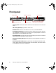
8507328.book Page 4 Thursday, February 15, 2001 11:28 AM Back panel Power connector Mouse port Keyboard port Serial port LAN2 port LAN1 port Video port Expansion card slots (2) Power connector connects the server power cord. The other end of the power cord plugs into an AC outlet, uninterruptible power supply (UPS), or power strip. Mouse port connects a PS/2-compatible mouse. LAN2 port lets you connect to a network. The adjacent indicator LEDs show LAN activity (green) and 100 Mbit speed (amber).
8507328.book Page 5 Thursday, February 15, 2001 11:28 AM Interior of system Air baffle Expansion cards Riser card System board Power supply Fan 2 Blower 2 Fan 1 Blower 1 Hot-plug backplane Hot-plug drive bays Diskette drive Control panel board CD drive (optional) Expansion cards you can install as many as two full-length PCI expansion cards. Riser card supports as many as two full-length PCI expansion cards. System board see “System board” on page 6. Fans provide cooling for the system.
8507328.book Page 6 Thursday, February 15, 2001 11:28 AM Hot-plug bays support up to three 1-inch high, 3.5-inch Ultra160 SCA SCSI hard drives. Empty drive bays contain empty carriers to control airflow and EMC characteristics. Diskette drive reads and writes 1.44-MB diskettes. CD drive (optional) plays data or audio CDs.
8507328.
8507328.book Page 8 Thursday, February 15, 2001 11:28 AM Hot-plug backplane Power connector Data connector Back SCSI connector SCSI ID 0 SCSI connector SCSI ID 1 SCSI connector SCSI ID 2 Front Power connector connects the power cable from the power supply. Data connector connects the SCSI cable from the RAID controller. SCSI drive connectors (3) connect the three SCA SCSI drives. Install drives in increasing order of SCSI ID.
8507328.book Page 9 Thursday, February 15, 2001 11:28 AM Control panel board LAN1 LED System fault LED Power LED Fault LED reset button Power button LAN2 LED Blower fault LED Fan fault LED USB port USB connector Front panel connector System fault LED glows amber when a hardware or system failure occurs. Pressing the fault LED reset button turns this LED off, but does not correct the fault. Power LED glows green when the server has power and flashes green when the server is in power saving mode.
8507328.book Page 10 Thursday, February 15, 2001 11:28 AM USB connector connects the control panel to the system board. Front panel connector connects the controls on the front panel with the system board. Riser card The riser card includes a PCI bridge to support the two PCI expansion slots through the edge connector on the system board. PCI Slot 2 PCI Slot 1 Chassis intrusion switch System board connector PCI expansion slots provide support for as many as two 64-bit, 66 MHz PCI expansion cards.
8507328.book Page 11 Thursday, February 15, 2001 11:28 AM 2 System Setup Setting up the server Use the instructions in the Gateway 7450R Rackmount Installation Guide that came with the server to assemble the server. You should prepare a safe working environment before assembling the server by following these guidelines: Important Keep the boxes and packing material. If you need to send the server to Gateway for repairs, you must use the original packaging or your warranty may be voided.
8507328.book Page 12 Thursday, February 15, 2001 11:28 AM ■ Plug the server into a wall outlet, power strip, or uninterruptible power supply (UPS). Warning For the power supply of this equipment, an approved power cord has to be used. For a rated current up to 6 A and an equipment weight up to 6 kg, a power cord not lighter than H05VV-F, 3 G, 0.75 mm2, has to be used. Warning Zum Netzanschluß dieses Gerätes ist eine geprüfte Leitung zu verwenden.
8507328.book Page 13 Thursday, February 15, 2001 11:28 AM 4 Turn on the server. The power LED on the control panel is green when the power is on. This same LED is amber when there is AC power connected to the server, but the server is off. If nothing happens when you turn on the system: ■ Make sure that the power cables are securely plugged in and that the power strip or UPS (if you are using one) is plugged in and turned on.
8507328.book Page 14 Thursday, February 15, 2001 11:28 AM If you need to return to the previous dialog box to change any of your entries, click Back. 4 Restart the server. The setup is complete. Important For all operating systems, refer to the appropriate operating system software manual for specific instructions. Turning off the server Every time you turn off the server, shut down the operating system first. You may lose data if you do not follow the proper procedure.
8507328.book Page 15 Thursday, February 15, 2001 11:28 AM Resetting the server If your server does not respond to keyboard or mouse input, you may have to close programs that are not responding. If closing unresponsive programs does not restore your server to normal operation, you may have to perform a forced shut down and restart the server. To close unresponsive programs and shut down the server in Windows NT: 1 Press CTRL+ALT+DEL. A window opens that lets you close a program that is not responding.
8507328.
8507328.book Page 17 Thursday, February 15, 2001 11:28 AM 3 Case Access Preventing static electricity discharge Before opening the server case, follow these precautions to prevent damage from static electricity. When opening your server case, always perform the following procedure. Caution Static electricity can permanently damage electronic components in your server. Prevent electrostatic damage to your server by following static electricity precautions every time you open your server case.
8507328.book Page 18 Thursday, February 15, 2001 11:28 AM ■ Always hold cards by their edges and their metal mounting brackets. Avoid touching components on the cards and the edge connectors that connect to expansion slots. Never slide cards or other parts over any surface. Opening the case Important All references to front, back, left, or right on the server are based on the server being in a normal position, as viewed from the front.
8507328.book Page 19 Thursday, February 15, 2001 11:28 AM 3 Remove the two thumbscrews from the top of the flanges at the sides of the front panel. Thumbscrew H PUS PU S H Thumbscrew Flange Flange 4 Slide the top panel slightly to the back. 5 Lift the panel up and away from the chassis.
8507328.book Page 20 Thursday, February 15, 2001 11:28 AM Closing the case Close the case as soon as you finish installing or removing components so that dust and dirt do not collect inside the server and to maintain the thermal characteristics of the server interior. Caution Operating the server with the top panel removed adversely affects the thermal characteristics of the server interior and can result in overheating of and possible damage to the hard drives or the processors.
8507328.book Page 21 Thursday, February 15, 2001 11:28 AM Replacing and Adding Internal Devices 4 Drives There are several types of drives and similar devices that can be installed in the server. Preparing to replace or add a drive One diskette drive and at least one 1-inch high, 3.5-inch hot-plug hard drive are included with the server. You can add an optional slimline CD drive and as many as two additional hot-plug drives for a total of three hot-plug drives.
8507328.book Page 22 Thursday, February 15, 2001 11:28 AM Drive cabling information The system includes two different types of drive cables. Each drive cable is clearly labeled, indicating the cable type and showing which end to connect to the appropriate connector on the system board and which end to connect to the drive. ■ Use the diskette drive cable to connect the diskette drive. ■ Use the SCSI LVD cable to connect the hot-plug backplane to the integrated SCSI controller on the system board.
8507328.book Page 23 Thursday, February 15, 2001 11:28 AM 4 Remove the diskette drive assembly by removing the two screws near the back of the drive. Slots Hooks Hooks 5 Slide the drive assembly back slightly to disengage the hooks on the drive bay from the slots on the diskette drive bracket, then pull the drive assembly out of the chassis. 6 If necessary, set any jumpers on the replacement drive assembly. (See your drive documentation for proper drive jumper settings and cable orientation.
8507328.book Page 24 Thursday, February 15, 2001 11:28 AM Installing a CD drive The CD drive bay is in the center of the front panel. If the server did not include a CD drive, a blank or “dummy” unit occupies the bay and must be removed. Important The CD drive assembly should include the bracket and small circuit board. If it does not, contact Client Care. To install your CD drive assembly: 1 Turn off the system and disconnect the power cord and all other external peripheral devices. 2 Open the case.
8507328.book Page 25 Thursday, February 15, 2001 11:28 AM 5 If necessary, set any jumpers on the CD drive assembly. (See your drive documentation for proper drive jumper settings and cable orientation.) 6 Place the CD drive assembly in the chassis. Make sure the hooks extend through the slots on the bracket, then slide the CD drive assembly forward. 7 Secure the CD drive assembly with the two screws you removed in Step 4.
8507328.book Page 26 Thursday, February 15, 2001 11:28 AM 4 Remove the two screws that secure the CD drive assembly to the chassis. Slots Hooks Hooks 5 Slide the drive assembly back slightly to disengage the hooks on the drive bay from the slots on the CD drive bracket, then pull the drive assembly out of the chassis. 6 If necessary, set any jumpers on the replacement drive. (See your drive documentation for proper drive jumper settings and cable orientation.
8507328.book Page 27 Thursday, February 15, 2001 11:28 AM Replacing a hot-plug drive The hot-plug drives are located along the bottom edge of the front panel as you face the system. The hot-plug bay supports as many as three 1-inch high, 3.5-inch SCSI hard drives. The hot-plug drives are assigned SCSI ID numbers by the hot-plug backplane with the drive on the left end of the hot-plug bay assigned SCSI ID 0.
8507328.book Page 28 Thursday, February 15, 2001 11:28 AM 3 Remove the drive from the drive bay by unclipping the retention lever and rotating the lever out away from the front of the system. Retention lever 4 Continue pulling outward until the drive is entirely out of the system. 5 Remove the six screws that secure the drive to the carrier. 6 Remove the drive from the carrier.
8507328.book Page 29 Thursday, February 15, 2001 11:28 AM 7 Install the new drive in the carrier using the six screws you removed in Step 5. Make sure the drive is oriented correctly. 8 Align the drive carrier with the slots at the sides of the drive bay. Leave the retention lever in the open position. 9 Push the drive all of the way into the drive bay until the connector at the back joins with the corresponding connector on the SCSI backplane, then firmly close the lever.
8507328.book Page 30 Thursday, February 15, 2001 11:28 AM The hot-plug drives are assigned SCSI ID numbers by the hot-plug backplane with the drive on the left end of the hot-plug bay assigned SCSI ID 0. The backplane assigns SCSI IDs to the other drives in order up to SCSI ID 2 on the right end of the hot-plug bay. See “Hot-plug backplane” on page 8 for the locations of the drives by SCSI ID number. Important Gateway tests and verifies the operation and compatibility of the drives we sell.
8507328.book Page 31 Thursday, February 15, 2001 11:28 AM 4 Align the drive carrier with the slots at the sides of the drive bay. Leave the retention lever in the open position. 5 Push the drive all of the way into the drive bay until the connector at the back joins with the corresponding connector on the SCSI backplane, then firmly close the lever. 6 Run any necessary utilities to setup the new drive. See the utility software documentation for details.
8507328.book Page 32 Thursday, February 15, 2001 11:28 AM Replacing memory To replace DIMMs: 1 Turn off the system and disconnect the power cord and all other external peripheral devices. 2 Open the case. See “Opening the case” on page 18 and “Preventing static electricity discharge” on page 17. 3 Pull open the socket clamps on each side of the DIMM socket, then lift the DIMM out of the socket. Store the DIMM in an anti-static container.
8507328.book Page 33 Thursday, February 15, 2001 11:28 AM Adding memory To add DIMMs: 1 Turn off the system and disconnect the power cord and all other external peripheral devices. 2 Open the case. See “Opening the case” on page 18 and “Preventing static electricity discharge” on page 17. 3 Pull open the socket clamps on each side of the DIMM socket. 4 Insert the new DIMM into the socket, aligning the two notches in the DIMM with the two notches in the DIMM socket.
8507328.book Page 34 Thursday, February 15, 2001 11:28 AM Processors The system is compatible with the Intel® Pentium® III 866 MHz and faster processors with 133 MHz front-side bus (FSB). As many as two processors may be installed in the system. You do not need to install additional voltage regulator modules (VRMs), because the VRMs for both processors are built into the system board. The server uses different heat sinks for the primary and secondary processors.
8507328.book Page 35 Thursday, February 15, 2001 11:28 AM 4 Unclip the heatsink by pressing down on the top of the clip, then pushing the top of the clip toward the heatsink. Clip Hook 5 Lift the heatsink off of the processor. 6 Remove the processor by pulling the lever arm slightly away from the processor socket, then lifting it to a ninety-degree angle. 1 2 7 Lift the old processor out of the socket.
8507328.book Page 36 Thursday, February 15, 2001 11:28 AM 9 Secure the new processor by pushing the lever arm all of the way down until it clicks into place. 10 Replace the heatsink. 11 Place the fixed end of the heatsink clip over the hook on the processor socket first, then press the hinged end of the clip over the hook on the other side of the processor socket. 12 Close the case. See “Closing the case” on page 20. 13 Reconnect the power cord and all other cords you removed, then turn on the system.
8507328.book Page 37 Thursday, February 15, 2001 11:28 AM To replace the secondary processor: 1 Turn off the system and disconnect the power cord and all external peripheral devices. 2 Open the case. See “Opening the case” on page 18 and “Preventing static electricity discharge” on page 17. 3 Unclip the heatsink by pressing down on the top of the clip, then pushing the top of the clip toward the heatsink.
8507328.book Page 38 Thursday, February 15, 2001 11:28 AM 6 Insert the new processor by aligning pin one on the processor and the socket, then place the processor into the socket. 1 Pin 1 2 7 Secure the new processor by pushing the lever arm all of the way down until it clicks into place. 8 Replace the heatsink. Make sure that the heatsink is oriented properly over the processor and socket. 9 Close the case. See “Closing the case” on page 20.
8507328.book Page 39 Thursday, February 15, 2001 11:28 AM Adding a secondary processor The system is compatible with the Intel® Pentium® III 866 MHz and faster processors with 133 MHz front-side bus (FSB). As many as two processors may be installed in the system. The second processor must match the first processor in speed or the system functions at the speed of the slowest processor. When adding a second processor order a processor upgrade kit from The Accessory Store on the Gateway Web site.
8507328.book Page 40 Thursday, February 15, 2001 11:28 AM 6 Place the secondary (large) heatsink over the processor and socket, making sure that it is oriented properly. 7 Place the fixed end of the clip over the hook on the back of the socket, then press the hinged end of the clip over the hook on the front of the socket. 8 Close the case. (See “Closing the case” on page 20.) 9 Reconnect the power cord and all other cords you removed, then turn on the system.
8507328.book Page 41 Thursday, February 15, 2001 11:28 AM Open the BIOS Setup utility and write down all the values in the various menus before replacing the battery. Replacing the battery resets the BIOS Setup utility to its default values. Warning Danger of explosion if battery is incorrectly replaced. Replace only with the same or equivalent type recommended by manufacturer. Dispose of used batteries according to manufacturer’s instructions. Warnung Explosionsgefahr bel falsch eingebautter batterie.
8507328.book Page 42 Thursday, February 15, 2001 11:28 AM 6 Remove the cable over the air baffle and pull the air baffle out of the server. Air baffle 7 Using your finger or a small, flat-bladed screwdriver, carefully press the small spring clip to remove the battery from its socket on the system board. Spring clip 8 Press the new battery in the socket with the positive pole up. Be sure you have pressed the battery down far enough for it to contact the base of the socket (it should snap into place).
8507328.book Page 43 Thursday, February 15, 2001 11:28 AM Expansion cards The server has two expansion slots on the riser card that can be used for a variety of expansion cards. These slots support 64-bit, 66 MHz PCI cards. Both slots will hold full-length, full-height cards. Replacing an expansion card You must install an expansion card in slot 1 before you can install an expansion card in slot 2.
8507328.book Page 44 Thursday, February 15, 2001 11:28 AM 6 Remove the card holder from the other end of the expansion card. Card holder 7 Remove the old expansion card from the slot. 8 Set any jumpers or switches on the new expansion card, then install the new expansion card in the empty slot.
8507328.book Page 45 Thursday, February 15, 2001 11:28 AM 9 If the card is full-length, insert the card extension into the card guide. The card extension in slot 1 fits below the card guide and the card extension in slot 2 fits into the groove in the card guide. Card guide Card extensions 10 Replace the card holder over the card guide and the end of the expansion card. See the illustration following Step 6. 11 Replace the screw in the expansion card bracket to secure the card.
8507328.book Page 46 Thursday, February 15, 2001 11:28 AM To add an expansion card: 1 Set any jumpers and switches on the card, if required in the card instructions. 2 Turn off the server, disconnect the power cord and all external peripheral devices. 3 Open the case. See “Opening the case” on page 18 and “Preventing static electricity discharge” on page 17. 4 Locate an available slot and remove the slot cover by removing the screw on the expansion card bracket, then remove the slot cover.
8507328.book Page 47 Thursday, February 15, 2001 11:28 AM 5 Remove the card holder from the other end of the expansion card. Card holder 6 Set any jumpers or switches on the expansion card, then install the expansion card in the empty slot. 7 If the card is full-length, insert the card extension into the card guide. The card extension in slot 1 fits below the card guide and the card extension in slot 2 fits into the groove in the card guide.
8507328.book Page 48 Thursday, February 15, 2001 11:28 AM 8 Replace the card holder over the card guide and the end of the expansion card. 9 Replace the screw in the expansion card bracket to secure the card. Expansion card bracket Screw Expansion card 10 Connect any cables to the card. See the card documentation for the proper cable orientation. 11 Close the case. See “Closing the case” on page 20. 12 Reconnect the peripherals and the power cord, then turn on the system.
8507328.book Page 49 Thursday, February 15, 2001 11:28 AM 3 Disconnect the cables from the power supply to all other internal parts. Note their positions and orientations so you can connect the cables from the new power supply. 4 Remove the air duct between the power supply and the number two blower.
8507328.book Page 50 Thursday, February 15, 2001 11:28 AM 5 Remove the three screws that secure the power supply to the back panel, then slide the power supply toward the front of the server to free it from the pin on the bottom of the server and lift it out of the chassis. Pin 6 Place the new power supply in the chassis making sure the pin on the bottom of the chassis passes through the hole on the power supply bracket. 7 Replace the screws you removed in Step 5 above.
8507328.book Page 51 Thursday, February 15, 2001 11:28 AM To replace a blower: 1 Use the system management software to determine which blower has failed. 2 Turn off the system and disconnect the power cord and external peripherals. 3 Open the case. See “Opening the case” on page 18 and “Preventing static electricity discharge” on page 17. 4 Unplug the correct blower cable from the system board and remove the cable from the cable clamps. 5 Lift the blower off of the pins on the bottom of the chassis.
8507328.book Page 52 Thursday, February 15, 2001 11:28 AM Replacing a fan Fan 1 is located between the expansion cards and the drive bays and fan 2 is located between the two blowers. See “Interior of system” on page 5 for the locations of the fans. To replace a fan: 1 Use the system management software to determine which fan has failed. 2 Turn off the system and disconnect the power cord and external peripherals. 3 Open the case.
8507328.book Page 53 Thursday, February 15, 2001 11:28 AM 7 Plug the fan connector into the connector on the system board and replace the cable in the cable clamps. Make sure the cable does not interfere with airflow and will not be pinched when you close the cover. 8 Close the case. See “Closing the case” on page 20. 9 Reconnect the power cord and external peripherals, then turn on the system.
8507328.book Page 54 Thursday, February 15, 2001 11:28 AM 5 Install the new control panel board by replacing the three screws you removed in Step 4. 6 Plug the front panel cables into the appropriate connectors on the control panel board. 7 Close the case. See “Closing the case” on page 20. 8 Reconnect the power cord and the external peripherals, then turn on the system. Replacing the hot-plug backplane The three drive hot-plug backplane is at the back of the hot-plug drive cage.
8507328.book Page 55 Thursday, February 15, 2001 11:28 AM 5 Remove the four screws that secure the hot-plug backplane assembly in the chassis, then lift the assembly out of the server. 6 Place the new backplane assembly in the chassis and secure it using the four screws you removed in Step 5. 7 Reconnect all cables on the backplane to the correct connectors. 8 Replace all hot-plug drives. Make sure that you replace them in the same slots that they were in before you removed them. 9 Close the case.
8507328.book Page 56 Thursday, February 15, 2001 11:28 AM To replace the riser card: 1 Turn off the system and disconnect the power cord and all external peripheral devices. 2 Open the case. See “Opening the case” on page 18 and “Preventing static electricity discharge” on page 17. 3 Remove any expansion cards installed in the system. See “Replacing an expansion card” on page 43. 4 Remove the two screws that secure the riser card assembly to the chassis.
8507328.book Page 57 Thursday, February 15, 2001 11:28 AM 6 Remove the two screws that secure the riser card to the bracket. 7 Slide the riser card to the left on the bracket to free it from the pins on the bracket, then pull the riser card off of the bracket. 8 Place the new riser card on the bracket and secure it with the two screws you removed in Step 6. 9 Insert the new riser card assembly into the chassis and insert the system board edge connector into the connector on the back of the riser card.
8507328.book Page 58 Thursday, February 15, 2001 11:28 AM 3 Remove all expansion cards from the system. See “Replacing an expansion card” on page 43. 4 Remove the two screws that secure the riser card assembly to the chassis. 5 Disconnect the riser card from the edge connector on the system board, then lift the riser card assembly out of the chassis. 6 Disconnect all cables from the system board. Note the locations and orientations of the cables as you remove them.
8507328.book Page 59 Thursday, February 15, 2001 11:28 AM 8 Remove the eight screws that secure the system board to the chassis, then lift the system board out of the chassis. 9 Remove the new system board from its anti-static bag and set any jumpers that you may need to set for your configuration. See “System board” on page 6 and “Setting the system board jumpers and switches” on page 64. 10 Place the new system board in the chassis. 11 Replace the eight screws you removed in Step 8.
8507328.book Page 60 Thursday, February 15, 2001 11:28 AM 15 Replace any expansion cards you removed from the system in Step 3. See “Replacing an expansion card” on page 43. 16 Close the case. See “Closing the case” on page 20. 17 Reconnect all peripherals and the power cord, then turn on the system.
8507328.book Page 61 Thursday, February 15, 2001 11:28 AM 5 Using the BIOS Setup Utility About the BIOS Setup utility The server BIOS has a built-in setup utility that lets you configure several basic system characteristics. The settings are stored in battery-backed RAM and are retained even when the power is off. Enter the BIOS Setup utility by restarting the server, then pressing F2 when prompted during the startup process. The Main BIOS Setup utility screen opens.
8507328.book Page 62 Thursday, February 15, 2001 11:28 AM As you select items on the Main menu or in submenus, you see specific information related to the current selection in the Item Specific Help box. The command bar shows the keystrokes necessary to access help, navigate through the menus, and perform other functions. ■ F1 opens the Help screen, providing general help for using the BIOS Setup utility.
8507328.book Page 63 Thursday, February 15, 2001 11:28 AM Updating the BIOS If you need a new version of the BIOS, you can download the BIOS update from the technical support area on the Gateway Web site (www.gatewayatwork.com) and install the new version from a diskette.
8507328.book Page 64 Thursday, February 15, 2001 11:28 AM 7 Turn off the server. 8 Remove the diskette from the drive. 9 Open the case. 10 Set switch SW1-3 back to the off position. 11 Close the case. 12 Turn on the server. 13 As the server boots, press F2 to open the BIOS Setup utility. Save and exit from the BIOS Setup utility, even if you made no changes to the settings. If the server does not boot properly, repeat the BIOS recovery procedure.
8507328.book Page 65 Thursday, February 15, 2001 11:28 AM Setting the switches Switch bank SW1 is a four-switch bank that lets you clear the password, update the BIOS, or recover from a failed BIOS update attempt. The four switches each have a different function as shown in the table below. For the location of switch bank SW1, see “System board” on page 6.
8507328.
8507328.book Page 67 Thursday, February 15, 2001 11:28 AM 6 Managing the Server Avoiding power source problems Surge suppressors, line conditioners, and uninterruptible power supplies can help protect the server against power source problems. Surge suppressors During a power surge, the voltage level of electricity coming into the server can increase far above normal levels and cause data loss or system damage.
8507328.book Page 68 Thursday, February 15, 2001 11:28 AM Line conditioners A line conditioner protects the server from the small fluctuations in voltage from an electrical supply. Most systems can handle this variation (line noise) without problems. However, some electrical sources include more line noise than normal. Line noise can also be a problem if the server is located near, or shares a circuit with, a device that causes electromagnetic interference, such as a television or a motor.
8507328.book Page 69 Thursday, February 15, 2001 11:28 AM Use Check Disk from once a week to once a month, depending on how often you use the server. Also use Check Disk if you have any hard drive problems. To use Check Disk: 1 Double-click the My Computer icon. The My Computer window opens. 2 Right-click the drive you want to check. 3 Select Properties. The drive’s properties window opens. 4 Click the Tools tab. 5 At Error-checking, click Check Now. The Check Disk window opens.
8507328.book Page 70 Thursday, February 15, 2001 11:28 AM Backing up files Regularly backing up your files protects you from losing data and lets you keep fewer files on your hard drive. Back up old files to the network, a large capacity disk drive, or tape drive and delete the files from the hard drive. This server does not support the installation of an internal large capacity disk drive or tape storage drive.
8507328.book Page 71 Thursday, February 15, 2001 11:28 AM Deleting temporary Internet files As you visit Web sites, your browser stores temporary Internet files on your hard drive in a memory cache and a disk cache. Files in the memory cache are removed when you turn off your server. Files are saved in the disk cache until the space designated for the cache is full. See your browser’s Help files for instructions on emptying the disk cache.
8507328.book Page 72 Thursday, February 15, 2001 11:28 AM Protecting the server against viruses A virus is a program that attaches itself to a program or data file on a computer, then spreads from one computer to another. Viruses can damage data, cause computers to malfunction, and can display annoying or offensive messages. Some viruses can go unnoticed for long periods of time because they are activated by a certain date or time.
8507328.book Page 73 Thursday, February 15, 2001 11:28 AM System administration and control The server has two server-management tools that you can use to administer and control the server. These tools are ManageX Event Manager and the Simple Network Management Protocol (SNMP) agent.
8507328.book Page 74 Thursday, February 15, 2001 11:28 AM To install the SNMP agent in Windows NT: 1 Add the IP address or hostname of the server to the SNMP setup. This SNMP service routes SNMP service alerts to ManageX. 2 Install ManageX from the Server Companion CD (SCCD). 3 Run SETUP.EXE from the SCCD. The default directory is \Program Files\7450R Agent. 4 Restart the server. 5 Setup ManageX. See “Setting up ManageX” on page 75.
8507328.book Page 75 Thursday, February 15, 2001 11:28 AM 9 Select Other devices, then click Have Disk. 10 Browse the SCCD to find 7450R.inf. 11 Select the 7450R Driver. 12 If the server does not reboot automatically, reboot the server. 13 Setup ManageX (see “Setting up ManageX” on page 75). Setting up ManageX To setup ManageX: 1 Run ManageX. 2 Select WBEM Browser, Systems Management Server, then 7450R Components to see the server information. This step displays the WBEM Object detail window.
8507328.book Page 76 Thursday, February 15, 2001 11:28 AM System security You can also set security measures in the BIOS Setup utility which establishes passwords and automatic system lockouts. The system also includes server management software that monitors the chassis intrusion switch. Mechanical access and monitoring The system includes a chassis intrusion switch. When the top panel is opened, the switch transmits a signal to the system board, where server management software processes the signal.
07328.book Page 77 Thursday, February 15, 2001 11:28 AM Summary of software security features The following table lists the software security features and describes what protection each offers. In general, to enable or set the features listed here, you must run the BIOS Setup utility and go to the Security Menu. The table also refers to other Setup utility menus. For more information, see “About the BIOS Setup utility” on page 61.
8507328.book Page 78 Thursday, February 15, 2001 11:28 AM When you set up Windows NT, you are prompted to create a startup diskette. If you did not choose to create a startup diskette at that time, you may create one later by running the Windows NT upgrade/installation program. Perform this process by going to the DOS Command Prompt, changing to the C:\I386 subdirectory and typing winnt32/ox. Press ENTER and follow the prompts.
8507328.book Page 79 Thursday, February 15, 2001 11:28 AM 7 Troubleshooting Introduction If the server does not operate correctly, re-read the instructions for the procedures you have performed. If an error occurs within an application, refer to the documentation supplied with the software. This section identifies solutions to some possible problems. Troubleshooting checklist Before turning on the system, make sure that: ■ The power cord is connected to the power connector and an AC outlet.
8507328.book Page 80 Thursday, February 15, 2001 11:28 AM Troubleshooting guidelines As you troubleshoot the server, keep the following guidelines in mind: ■ Never remove the chassis cover while the server is turned on. ■ Do not attempt to open the monitor. Even if the power is disconnected, stored energy in the components can be dangerous. ■ If a peripheral does not work, make sure that all connections are secure. ■ If you see an error message on the screen, write it down, word for word.
8507328.book Page 81 Thursday, February 15, 2001 11:28 AM CD problems The system does not recognize the CD drive Probable cause Solution The CD is not intended for PC use Make sure that the disc is PC-compatible. The CD is loaded incorrectly Make sure that the label is facing up, then try again. The CD is scratched or dirty Try cleaning the CD with a lint-free cloth. Make sure the disk is not scratched.
8507328.book Page 82 Thursday, February 15, 2001 11:28 AM Memory and processor problems The system detected memory errors during start up Probable cause Solution Memory was added or removed, and the new configuration was not saved in the BIOS Setup utility Open the BIOS Setup utility and save the new memory configuration. The memory was installed incorrectly Make sure that the memory is properly seated and oriented. A memory chip is faulty Replace the card with the faulty chip.
8507328.book Page 83 Thursday, February 15, 2001 11:28 AM Probable cause Solution The device cables are not installed correctly Open the system, then check all cables between the controller and the device. The system does not recognize the diskette drive Probable cause Solution The diskette drive may be configured incorrectly Restart your server, then press F2 to enter the BIOS Setup utility. In the Boot | Removable Devices menu, make sure that the diskette drive parameters are set correctly.
8507328.book Page 84 Thursday, February 15, 2001 11:28 AM The system does not recognize an expansion card Probable cause Solution The interrupt or I/O address is set incorrectly Check the address configuration of the adapter card and make sure that it does not conflict with another card in the system. The card has not been configured through the software Configure the card with the appropriate software.
8507328.book Page 85 Thursday, February 15, 2001 11:28 AM Probable cause Solution The printer is not designated as the default printer If the printer that you are trying to print to is not the default printer, make sure that you have selected it through the program printer setup function. The printer has not been added to the system In the Printers window (Start | Settings | Printers), double-click Add Printer. Follow the on-screen instructions for adding the new printer.
8507328.book Page 86 Thursday, February 15, 2001 11:28 AM The mouse does not work Probable cause Solution The mouse is not plugged in or connected properly Make sure that the cable is plugged in correctly. The mouse driver did not load when the system started Load the appropriate mouse driver manually or contact technical support. The mouse is defective Try a mouse that you know is working.
8507328.book Page 87 Thursday, February 15, 2001 11:28 AM The image on the screen is dim or difficult to read Probable cause Solution The monitor brightness and contrast controls are turned down Adjust the brightness and contrast knobs until the text becomes clear. Sunlight is glaring off the display Position the monitor away from the sun or a window. The monitor may be old Replace the monitor.
8507328.book Page 88 Thursday, February 15, 2001 11:28 AM Probable cause Solution The surge protector or UPS is damaged Disconnect the monitor power cable, then connect it directly to the power source. The monitor is too close to a source of electrical interference Move the monitor away from sources of electrical interference, such as televisions, unshielded speakers, microwave ovens, fluorescent lights, and metal beams or shelves.
8507328.
8507328.
8507328.
8507328.
8507328.
8507328.
8507328.book Page 95 Thursday, February 15, 2001 11:28 AM Safety, Regulatory, and Notices A The Gateway 7450R Server originally shipped with a Class A rating according to FCC rules part 15. Later modifications may have improved the rating to Class B. To check the rating of the system as shipped to you, check the FCC label at the back of the chassis for the rating.
8507328.book Page 96 Thursday, February 15, 2001 11:28 AM ■ Some products are equipped with a three-wire power cord to make sure that the product is properly grounded when in use. The plug on this cord will only fit into a grounding-type outlet. This is a safety feature. If you are unable to insert the plug into an outlet, contact an electrician to install the appropriate outlet. Warning For the power supply of this equipment, an approved power cord has to be used.
8507328.book Page 97 Thursday, February 15, 2001 11:28 AM Warnings WARNING: English (US) AVERTISSEMENT: Français WARNUNG: Deutsch AVVERTENZA: Italiano ADVERTENCIAS: Español The power supply in this product contains no user-serviceable parts. There may be more than one supply in this product. Refer servicing only to qualified personnel. Le bloc d’alimentation de ce produit ne contient aucune pièce pouvant être réparée par l'utilisateur. Ce produit peut contenir plus d'un bloc d'alimentation.
8507328.book Page 98 Thursday, February 15, 2001 11:28 AM 98 WARNING: English (US) AVERTISSEMENT: Français WARNUNG: Deutsch AVVERTENZA: Italiano ADVERTENCIAS: Español For proper cooling and airflow, always reinstall the chassis covers before turning on the system. Operating the system without the covers in place can damage system parts. To install the covers: 1 Check first to make sure you have not left loose tools or parts inside the system.
8507328.book Page 99 Thursday, February 15, 2001 11:28 AM Regulatory compliance statements Rack Mounting If rack mounted units are installed in a closed or multi-unit rack assembly, they may require further evaluation by Certification Agencies. The following items must be considered: ■ The ambient within the rack may be greater than room ambient. Installation should be such that the amount of airflow required for safe operation is not compromised.
8507328.book Page 100 Thursday, February 15, 2001 11:28 AM Product: Gateway 7450R Server For unique identification of the product configuration, please submit the 10-digit serial number found on the product to the responsible party. This device complies with Part 15 of the FCC Rules.
8507328.book Page 101 Thursday, February 15, 2001 11:28 AM Canadian users ICES-003 This digital apparatus does not exceed the Class A limits for radio noise emissions from digital apparatus as set out in the radio interference regulations of Industry Canada. Le présent appareil numérique n’émet pas de bruits radioélectriques dépassant les limites applicables aux appareils numériques de Classe A prescrites dans le règlement sur le brouillage radioélectrique édicté par Industrie Canada.
8507328.book Page 102 Thursday, February 15, 2001 11:28 AM - EN 55024:1998 according to EN 61000-3-2:1995 EN 61000-3-3:1995 European Telecommunication Information (for products fitted with EU approved modems) Marking by the symbol indicates compliance of this equipment to the Telecom Terminal Equipment and Satellite Earth Stations Directive 98/13/EEC.
8507328.book Page 103 Thursday, February 15, 2001 11:28 AM Australia and New Zealand users EMI statement This device has been tested and found to comply with the limits for a Class A digital device, pursuant to the Australian/New Zealand standard AS/NZS 3548 set out by the Australian Communications Authority and Radio Spectrum Management Agency.
8507328.book Page 104 Thursday, February 15, 2001 11:28 AM Laser safety statement All Gateway systems equipped with CD and DVD drives comply with the appropriate safety standards, including IEC 825. The laser devices in these components are classified as “Class 1 Laser Products” under a US Department of Health and Human Services (DHHS) Radiation Performance Standard. Should the unit ever need servicing contact an authorized service location.
8507328.
8507328.
8507328.book Page 107 Thursday, February 15, 2001 11:28 AM B System Specifications System Specifications The following specifications are for the standard configuration. The server may contain optional equipment. All specifications are subject to change. Processors As many as two Intel® Pentium III™ processors operating at 866 MHz and faster Cache 256K on processor RAM Four DIMM sockets support up to 4.
8507328.book Page 108 Thursday, February 15, 2001 11:28 AM Server management Monitoring, alerting, and logging of critical system information obtained from embedded sensors on the system board, including thermal levels, voltage levels, fan speeds, and chassis intrusion monitoring. Expansion slots Two 64-bit, 66 MHz PCI slots on the riser card Drive Bays One CD drive bay (drive optional), one diskette drive bay, and three hot-plug bays (at least one is occupied by a 1-inch high hot-plug drive).
8507328.book Page 109 Thursday, February 15, 2001 11:28 AM Vibration Operating 0.0032 g2/Hz 5–200 Hz, -6dB/octave 200–500 Hz Nonoperating 0.015 g2/Hz 5–200 Hz, -6dB/octave 200–500 Hz Altitude Operating 10,000 ft. max Nonoperating 50,000 ft. max Heat dissipation 422 BTU (loaded) 988 BTU (maximum) Acoustic noise <55dB * Maximum temperature refers to the inlet air temperature, which is the ambient air temperature within the rack cabinet, not the air temperature within the room.
8507328.
8507328.
8507328.
8507328.
8507328.
8507328.
8507328.