User Guide Gateway 9315 Server
Contents 1 Checking Out Your Gateway Server . . . . . . . . . . . . . . . . . . . . . . . . . . . . . . . . . . . . 1 Front . . . . . . . . . . . . . . . . . . . . . . . . . . . . . . . . . . . . . . . . . . . . . . . . . . . . . . . . . . . . . . . . . . . . Control panel . . . . . . . . . . . . . . . . . . . . . . . . . . . . . . . . . . . . . . . . . . . . . . . . . . . . . . . . . . Back . . . . . . . . . . . . . . . . . . . . . . . . . . . . . . . . . . . . . . . . . . . . . . . . . . . . . . . . . . .
4 Installing Components . . . . . . . . . . . . . . . . . . . . . . . . . . . . . . . . . . . . . . . . . . . . . . . . 35 Preparing to install components . . . . . . . . . . . . . . . . . . . . . . . . . . . . . . . . . . . . . . . . . . . . . . Selecting a place to work . . . . . . . . . . . . . . . . . . . . . . . . . . . . . . . . . . . . . . . . . . . . . . . Gathering the tools you need . . . . . . . . . . . . . . . . . . . . . . . . . . . . . . . . . . . . . . . . . . . . Getting Help . . . . . . . .
Before calling Gateway Customer Care . . . . . . . . . . . . . . . . . . . . . . . . . . . . . . . . . . . Telephone support . . . . . . . . . . . . . . . . . . . . . . . . . . . . . . . . . . . . . . . . . . . . . . . . . . . . Tutoring and training . . . . . . . . . . . . . . . . . . . . . . . . . . . . . . . . . . . . . . . . . . . . . . . . . . . . . Safety guidelines . . . . . . . . . . . . . . . . . . . . . . . . . . . . . . . . . . . . . . . . . . . . . . . . . . . . . . . . Error messages . . . . .
iv www.gateway.
Chapter 1 Checking Out Your Gateway Server ■ Locating drives, ports, jacks, and controls ■ Locating system board components ■ Available help resources 1
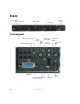
Front CD or DVD drive Hard drive Hard drive Control panel Hard drive Control panel LAN 1 activity indicator LAN 2 activity indicator Power button Hard drive activity LED Power/ sleep LED System ID button System fault LED Video port Non-maskable interrupt button (recessed) 2 www.gateway.
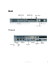
Back Low-profile PCI expansion card Full-height PCI expansion card Serial number Power connector I/O panel Power supply I/O panel Keyboard port PS/2 mouse port RJ-45 serial port USB ports LAN jacks Video port www.gateway.
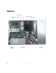
Interior CPU 2 socket Processor air duct DIMM slots PCI riser assembly 4 CPU 1 socket Fan module Power supply www.gateway.
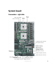
System board Connectors - right side CPU 2 fan header CPU 1 fan header CPU 1 socket CPU 2 socket +12V CPU power connector Fan board connector Diskette connector PCI fan connectors IDE connector 100-pin floppy/front panel/ATA connector IDE power connector Main power connector 50-pin front panel connector 34-pin front panel connector SATA 1 connector Front panel USB header OEM RMC connector Configuration jumpers Power supply connector SATA 0 connector www.gateway.
Connectors - left side DIMM slots Mouse (top) and Keyboard Serial port B (RJ-45) LAN 1 LAN 2 Video USB 1 USB 2 PCI riser card (low-profile) Diagnostic LEDs (4) PCI riser card (full-height) ID LED Battery Serial port A header Chassis intrusion header BIOS select jumper 6 www.gateway.
Getting Help In addition to your operating system’s documentation, you can use the following information resources to help you use your server. System Companion CD Use the System Companion CD to access file utilities, Windows 2003 Server drivers, and documentation for your server and its components. For more information, see Using Your System Companion CD. Gateway Web site Gateway provides a variety of information on its Web site to help you use your server. Visit the Gateway Web site at support.gateway.
8 www.gateway.
Chapter 2 Setting Up Your Server ■ Using your server safely ■ Installing your server into a cabinet ■ Starting and turning off your server ■ Setting up your operating system 9
Setting up the hardware To make sure that your working environment is safe: ■ Use a clean, dry, flat, stable surface for your server. Allow at least 6 inches at the back of the server for cabling and air circulation. ■ Use the instructions on your server’s setup poster to set up your hardware. ■ Use a grounded (three-prong) surge protector. A surge protector helps protect against AC power fluctuations.
Protecting from power source problems Surge protectors, line conditioners, and uninterruptible power supplies can help protect your server against power source problems. Surge protectors During a power surge, the voltage level of electricity coming into your server can increase to far above normal levels and cause data loss or server damage. Protect your server and peripheral devices by connecting them to a surge protector, which absorbs voltage surges and prevents them from reaching your server.
Uninterruptible power supplies Use an uninterruptible power supply (UPS) to protect your server from data loss during a total power failure. A UPS uses a battery to keep your server running temporarily during a power failure and lets you save your work and shut down your server. You cannot run your server for an extended period of time while using only the UPS. To buy a UPS, visit accessories.gateway.com. 12 www.gateway.
Mounting your server into a cabinet The cabinet mounting hardware included with your server should be used with EIA-310-D standard 4-post cabinets that have front and back vertical posts. The L-shaped cabinet mounting brackets can be used for mid-mounting on a 2-post cabinet, but that procedure is not covered here. If your cabinet is a different type, obtain mounting hardware from the cabinet manufacturer.
To mount your server in a cabinet: 1 2 Remove the two screws from each handle, then set the handles and screws aside. Align the slots in a server rail with the studs on the side of the server, then engage the slots with the studs and slide the rail back until it stops. (Your server may be different than the server shown in the example.
4 Place a disk guide over the disk guide screw hole towards the back of the server. Disk guide screw hole 5 Install a small screw through the disk guide and tighten the screw. Attach the remaining disk guide on the other side of the server. Disk guide Disk guide screw www.gateway.
16 6 Attach a nut bar to the inside of the two back cabinet posts using medium screws, but do not completely tighten the screws (leave them loose enough to allow insertion of the cabinet rail in the next step). 7 Insert the slotted foot at the back of each cabinet rail between the nut bar and the post, then tighten the screws. www.gateway.
8 With the front of the server facing you, lift the server and insert it into the cabinet from the front, then position the disk guides so they fit into the cabinet rails. (Your server may be different than the server shown in the example.) 9 Install a nut bar or mounting nuts on the front cabinet posts. Nut bar or mounting nuts 10 Push the server toward the back of the cabinet until the front of the server rails touch the front cabinet posts, then secure with two screws through each server rail.
Installing the bezel Important The bezel is held in place by the server handles. The handles are also used to slide the server in and out of the rack cabinet when mounted using the optional rails. To install the bezel: 1 With the server pulled out from the cabinet, align the holes in the handle with the holes in the front side of the server. 2 Attach the handles to the sides of the server with two mounting screws on each side. (Your server may be different than the server shown in the example.
6 Use a screw through each handle to secure the server to the cabinet posts. 7 Remove the bezel lock keys from the inside of the bezel, then snap on the bezel with the control panel area at the right. 8 To lock the bezel, insert the key into the lock and rotate it ¼ turn clockwise. To unlock it, rotate the key ¼ turn counter-clockwise. Removing the server from a cabinet To remove the server from a cabinet: Warning 1 2 Screws are required to support the front of the server.
Starting your server Before you start your server for the first time: ■ Make sure that the server and monitor are plugged into a power outlet or surge protector and that the surge protector (if you are using one) is turned on. ■ Make sure that all cables are connected securely to the correct ports and jacks on the back of the server. Caution When you connect peripheral devices to the server, make sure that your server and devices are turned off and the power cords are unplugged.
When the power LED is... It means... Green (steady on) The server is turned on. Green (blinking) The server is in sleep mode. Off The server is turned off. When the system fault LED is... It means... Green (steady on) The server is operating normally. Green (blinking) The server is operating in a degraded condition. Orange (steady on) The server is in a critical or unrecoverable condition. Orange (blinking) The server is in a noncritical condition. Off POST failure or full system stop.
Turning off your server Every time you turn off your server, first shut down the operating system. You may lose data if you do not follow the correct procedure. To turn off the server: 1 See the operating system’s documentation or online help for instructions on shutting down the operating system. Whenever possible, you should use the operating system’s shut down procedure instead of pressing the power button. Warning 2 The power button on the server does not turn off server AC power.
Configuring the RJ-45 serial port The RJ-45 serial port connector can be configured to support either a Data Set Ready (DSR), or a Data Carrier Detect (DCD) signal. The default configuration for your server supports DSR signals. To change the configuration from DSR to DCD signal support, a jumper (J8A3) must be changed on the system board. To change the RJ-45 serial port configuration to DCD signal support: 1 Follow the instructions in “Preventing static electricity discharge” on page 37.
Setting up the operating system If you ordered your server with the operating system already installed by Gateway, in most cases it is completely installed and the basic settings are already configured. The Windows Small Business Server operating system may require additional installation, depending on the version you ordered. See your operating system’s documentation for instructions on completing the installation or configuring advanced settings for your specific network.
Chapter 3 Maintaining Your Server ■ Caring for your server ■ Recording the BIOS configuration ■ Managing your server and network 25
Caring for your server To extend the life of your server: ■ Be careful not to bump or drop your server. ■ When transporting your server, we recommend that you put it in the original packaging materials. ■ Keep your server and magnetic media away from equipment that generates magnetic fields, such as unshielded speakers. ■ Avoid subjecting your server to extreme temperatures. Do not expose your server to heating ducts or other heat-generating objects.
■ Use a damp, lint-free cloth to clean your server and other parts of your server system. Do not use abrasive or solvent cleaners because they can damage the finish on components. ■ Keep the cooling vents free of dust. With your server turned off and unplugged, brush the dust away from the vents with a damp cloth, but be careful not to drip any water into the vents.
Preparing for system recovery If your system files are corrupted, you may not be able to start the server from the hard drive. Startup diskettes are diskettes that let you start the server and attempt to fix the problem. See your operating system’s documentation or online help for instructions on creating startup diskettes. Some operating systems also let you create an emergency repair diskette to back up critical operating system files.
System administration Gateway Systems Manager Gateway Systems Manager lets you manage multiple computers on a Windows™ network from a single window, then implement commands and policies across the network with a single action. With Gateway Systems Manager, you can run system management tasks which are triggered by certain events or conditions. Printed documentation comes with the Gateway Systems Manager CD. You can find additional documentation in the program’s online help.
4 5 Type the password and press ENTER, then type it again and press ENTER. Save your changes and close the BIOS Setup utility. To remove a BIOS security password: 1 Restart your server, then press F2 when the Gateway logo screen appears during startup. The BIOS Setup utility opens. 2 3 4 Select the Security menu, then select the password to remove. Enter the current password, then press ENTER. For the new password, leave the password field blank, then press ENTER. The password is removed.
Identifying your server While you are working on a cabinet that contains several slim servers, it can be difficult to keep track of which server or servers you are currently working on. The System ID indicator is a blue LED that you can turn on to help you locate the correct server. Your server has a System ID indicator in the front and in the back. In addition to the following procedure, the ID LED can also be turned on by using the Gateway Systems Manager software.
Updating the baseboard management controller firmware The baseboard management controller (BMC) performs several system management functions such as: ■ Monitoring server components (FRU) and sensor data records (SDR) (the information provided depends on the option selected) ■ Managing nonvolatile storage for the system event log and sensor data records ■ Interfacing with the emergency management port to send alerts and interact with remote management systems.
3 4 When the System Companion CD menu opens, select the FRU/SDR utility. Select one of the following options (if in doubt, choose the second option and update both): Update just the SDR repository - Select this option when sensor information needs to be changed. For example, if the CPU is upgraded to a higher speed or if memory is replaced. -ORUpdate the FRUs and the SDR repository - Select this option if have installed additional hardware. For example, additional memory.
34 www.gateway.
Chapter 4 Installing Components ■ Opening and closing the server case ■ Installing and replacing major server components 35
Preparing to install components Important You must open your server case to install components. If you are not comfortable with these procedures, get help from a computer service technician or contact Gateway Customer Care.
Preventing static electricity discharge The components inside your server are extremely sensitive to static electricity, also known as electrostatic discharge (ESD). Warning To avoid exposure to dangerous electrical voltages and moving parts, turn off your server and unplug the power cord and modem cable before opening the server case. Caution ESD can permanently damage electrostatic discharge-sensitive components in the server.
Opening the server case Because the components inside your server are extremely sensitive to static electricity, make sure that you follow the instructions at the beginning of this chapter to avoid static electricity damage. Caution For correct cooling and air flow, always reinstall the top panel before you turn on the server. Operating the server without the panel in place will cause the server to overheat.
6 Press and hold the panel release button, then slide the top panel toward the back of the server about 1/2 inch. Panel release button 7 Lift the top panel away from the server. Closing the server case Caution Whenever you add or remove components from your server, make sure that the various cables, both data and power, are routed correctly before reinstalling the top panel.
40 3 Slide the top panel toward the front of the server until it clicks into place. 4 5 6 Replace the shipping screw (if required). Replace the bezel (if required). Reconnect the power cord and all other cables. www.gateway.
Removing and installing air ducts, air dams, and baffle Your server has been engineered to provide correct airflow in the chassis for sufficient cooling of drives, processors, and power supplies. As your server configuration changes, the airflow within the chassis will need to be modified to accommodate those changes. Caution To ensure continued, reliable operation, always operate your server with the appropriate air ducts, air dams, and baffle in place.
Installing the processor air duct To install the processor air duct: 1 Place the processor air duct over the CPU sockets. The front edge of the air duct should contact the fan module and the top of the installed air duct should be flush with the top of the power supply. 2 Follow the instructions in “Closing the server case” on page 39. Removing the air baffle Caution To ensure continued, reliable operation, always operate your server with the appropriate air ducts, air dams, and baffle in place.
Important 3 Take note of the cable routing under and around the air baffle. You will need to re-route these cables when the baffle is reinstalled. Pull up on the air baffle to remove it from the server chassis. www.gateway.
Installing the air baffle Caution To ensure continued, reliable operation, always operate your server with the appropriate air ducts, air dams, and baffle in place. Failure to do this could result in equipment damage. To install the air baffle: 1 Place the air baffle into the chassis between the power supply and the hot-swap drive backplane, routing the cables as noted in the removal process. 2 3 Fit the tab that extends from the front of the baffle under the drive bay area.
Installing and removing drives Your server’s basic configuration includes one CD or DVD drive and as many as three SATA fixed hard drives. SATA hot-swap hard drives and a hot-swap backplane are optional. A USB diskette drive is also included (but not installed in the server). As you prepare to install drives, remember: ■ You must install a diskette drive in the left converted hard drive bay.
46 5 Remove the rails from the diskette drive conversion kit carrier by removing the four screws that secure the rails to the carrier. 6 Slide the diskette drive into the drive carrier. The back of the drive should go into the carrier first with the bottom of the drive facing down. 7 Align the holes in the sides of the diskette drive with the holes in the carrier and attach the drive to the carrier with the two screws that came with the diskette drive conversion kit. www.gateway.
8 Reattach the rails to the sides of the carrier with the four screws you previously removed. 9 Open the connector on the back of the diskette drive by pulling up on the connector cover. 10 Insert one end of the 26-pin diskette drive flat flex cable into the connector, then push down on the connector cover to lock it into place. 11 Insert the new drive assembly into the hard drive bay until it clicks into place. www.gateway.
48 12 Open the connector labeled Floppy Con on the backplane by pulling up on the connector cover. 13 Insert the other end of the diskette flat flex cable into the backplane connector, then push in on the connector cover to lock the cable into place. 14 15 16 Reinstall the bezel, if required, by snapping it into place on the front of the chassis. Follow the instructions in “Closing the server case” on page 39. Reconnect all power cords and peripheral device cables, then turn on the server. www.
Removing a diskette drive from the converted hard drive bay To remove a diskette drive from the converted drive bay: 1 Follow the instructions in “Preventing static electricity discharge” on page 37. Make sure that you turn off the server, then unplug the power cord and all other cables connected to the server. Caution The diskette drive is not hot-swappable. Before installing or removing the drive, make sure that power is turned off and the power cord is unplugged.
Installing a CD or DVD drive To install a CD or DVD drive: 1 Follow the instructions in “Preventing static electricity discharge” on page 37. Make sure that you turn off the server, then unplug the power cord and all other cables connected to the server. Caution 2 3 4 The CD or DVD drive is not hot-swappable. Before installing or removing the drive, make sure that power is turned off and the power cord is unplugged. Follow the instructions in “Opening the server case” on page 38.
6 Align the connector on the interposer board with the connector on the back of the CD or DVD drive, then attach the board to the drive with two screws (included with your server). 7 8 Attach the 44-pin CD drive cable to the back of the interposer board. 9 Connect the other end of the 44-pin cable into the connector on the backplane or the system board. 10 11 12 Reinstall the bezel, if required, by snapping it into place on the front of the chassis.
Removing a CD or DVD drive To removing a CD or DVD drive: 1 Follow the instructions in “Preventing static electricity discharge” on page 37. Make sure that you turn off the server, then unplug the power cord and all other cables connected to the server. Caution The CD or DVD drive is not hot-swappable. Before installing or removing the drive, make sure that power is turned off and the power cord is unplugged. 2 3 4 5 Follow the instructions in “Opening the server case” on page 38.
Installing or replacing a hard drive Use this procedure to add or replace hard drives in a drive bay. Your server supports as many as three 1-inch high 3.5-inch (fixed or hot-swap) SATA hard drives. You can purchase additional drives through your Gateway Sales representative. Important Gateway tests and verifies the operation and compatibility of the drives it sells. Especially in a hot-swap or mission-critical environment, additional or replacement drives must conform to Gateway standards.
54 5 Remove the four screws that attach the plastic retention device or the previously installed hard drive to the drive carrier. Two screws are at each side of the retention device or the hard drive. Store the plastic retention device for future use. 6 With the drive circuit-side down, position the connector end of the drive so that it is facing the back of the carrier. 7 Attach the hard drive to the carrier using the four screws removed from the carrier.
9 If it is not already installed, connect the SATA power cable adapter (supplied with the fixed drive kit) to the 3x2 power supply cable from your power supply. 10 For each drive you install, route one SATA data cable from the server board or add-in card to the hard drive, with the right-angle end of the SATA data cable connected to the server board or add-in card SATA connector.
11 Connect the loose end of the data cable to the rear of the SATA drive. Air baffle tab Air baffle back cutout Air baffle cutout Air baffle 56 www.gateway.
Important Power cables for drives installed to the right side of the air baffle must be routed beneath the front cutout in the underside of the air baffle. The power cable for a drive installed to the left of the air baffle does not need to be routed under the air baffle. You may need to remove the air baffle to route cables underneath it. Air baffle Air baffle cutout 12 13 14 15 Connect the SATA power cable adapter end(s) to the rear of the SATA drive.
Removing a fixed SATA hard drive Use these instructions only if you have installed the fixed drive kit. Caution Fixed drives are not hot swappable. Before installing or removing the drive, make sure that power is turned off and the power cord is unplugged. To remove a fixed SATA hard drive: 1 Follow the instructions in “Preventing static electricity discharge” on page 37. Make sure that you turn off the server, then unplug the power cord and all other cables connected to the server.
Installing a hot-swap hard drive To install a hot-swap hard drive: 1 Unlock the bezel (if necessary) and remove it by pulling it from the chassis. Caution Before you remove a failed drive, use the appropriate software and utilities installed on the server to stop all activity on the failed drive. Instructions for using the software are provided by the software manufacturer. Failure to do so may destroy the data on the drive.
If you are adding a new drive, remove the four screws that secure the hard drive spacer to the drive tray, then remove the spacer from the tray. 60 5 Line up the screw holes in the new drive with the holes in the side of the drive tray, then secure the drive to the tray with the four screws you removed in Step 4. 6 Make sure that the tray’s release lever is open, then slide the new drive into the empty hot-swap bay.
Configuring your onboard RAID solution Your server comes equipped with an onboard, chipset SATA RAID solution, which supports RAID levels 0 (striping) and 1 (mirroring). The onboard RAID solution can be enabled in the BIOS (page 133) and configured by launching the RAID BIOS console during the boot process. Configuring the onboard SATA RAID solution Level Description and use Pros Cons Number of drives Fault Tolerant 0 Data divided into blocks and distributed sequentially (pure striping).
9 Press and hold the CTRL key, then press the E key. The RAID BIOS console will open. Important 10 11 When you press CTRL + E to configure the SATA RAID, you will see the following error message: Error (0146): Insufficient Memory to Shadow PCI ROM. This error message can be ignored. Configure the RAID options, then exit the RAID BIOS console. Reboot the server. To configure the SATA RAID solution: 1 Open the BIOS Setup utility as described in the previous procedure.
5 Press the SPACEBAR to select the array. The Logical Drive Configuration screen opens. 6 7 Select the physical drives to associate with the current array, then press the SPACEBAR. 8 9 10 11 12 Set the RAID level for the logical drive by highlighting RAID and pressing ENTER. The available RAID levels for the current logical drive are shown. Select a RAID level, then press ENTER. Set the RAID logical drive size and stripe size.
Filling empty drive bays Empty drive bays in the server must be filled by filler panels, empty drive carriers, or empty drive trays, as appropriate. With the bezel removed, install the appropriate carrier or filler panel, then replace the bezel by snapping it into place on the front of the server. 64 www.gateway.
Installing memory Your server supports from 256 MB to 12 GB* of total DDR333 or DDR266 memory. Supported DIMM sizes include 256 MB, 512 MB, 1 GB, and 2 GB. Caution Modules must be installed in banks in identical pairs. Use only DDR266 or DDR333 compliant, 184-pin, SDRAM registered x72 ECC, LP (low profile) DIMM memory modules. Install memory first into Bank 1, then Bank 2, then Bank 3. If memory is installed incorrectly, your server will not start.
Supported DDR266 DIMM populations Bank 3 - DIMMs 3A and 3B Bank 2 - DIMMs 2A and 2B Bank 1 - DIMMs 1A and 1B Single row Single row Single row Empty Single row Single row Empty Empty Single row Double row Double row Double row Empty Double row Double row Empty Empty Double row Double row Single row Single row Double row Double row Single row Empty Double row Single row Supported DDR333 DIMM populations Bank 3 - DIMMs 3A and 3B Bank 2 - DIMMs 2A and 2B Bank 1 - DIMMs 1A and 1B
maintained as a spare, only 75% of the installed memory is usable. For example, if six 2 GB DIMMs are installed, only four are actively used (the other two are used as spares), so the maximum usable memory for this configuration would be 8 GB. A DIMM fault LED adjacent to the DIMM slot will light orange to indicate the failed memory module. To install or replace memory: 1 Follow the instructions in “Preventing static electricity discharge” on page 37.
68 6 Turn on the server, then make sure that the operating system completely loads. If you receive an error, see “Memory” on page 120. 7 Follow the instructions in “Updating the FRU/SDR” on page 32. www.gateway.
Removing and Installing PCI expansion cards Caution The PCI riser assembly and individual PCI expansion cards are not hot-swappable. Before installing or removing the any part of the assembly, make sure that power is turned off and the power cord is unplugged. Removing and installing the PCI riser assembly To remove and install the PCI riser assembly: 1 Follow the instructions in “Preventing static electricity discharge” on page 37.
5 If you are installing or replacing a PCI expansion card, follow the instructions in “Removing and installing a PCI expansion card” on page 71. Caution Do not touch the contacts on the bottom part of the expansion card. Touching the contacts can cause electrostatic damage to the card. - OR If you are installing or replacing the PCI riser connector, follow the instructions in “Removing and installing a PCI riser connector” on page 72.
Removing and installing a PCI expansion card To remove and install a PCI expansion card: 1 Follow the instructions in “Preventing static electricity discharge” on page 37. Make sure that you turn off the server, then unplug the power cord and all other cables connected to the server. 2 3 4 Follow the instructions in “Opening the server case” on page 38. 5 If you are replacing a card, remove the old expansion card.
8 9 10 Install the PCI riser assembly back into the server by following the instructions in “Removing and installing the PCI riser assembly” on page 69. Follow the instructions in “Closing the server case” on page 39. See the card’s documentation for software installation instructions.
5 Push back on the blue release lever at the end of the PCI riser connector. While holding the lever back, push firmly on the other edge of the board to disengage the board from the riser. PCI riser connector Riser retention pin Riser locking lever 6 7 Place the PCI riser connector in a static-free bag for future use. 8 Press and hold the blue riser locking lever, then place the PCI riser connector onto the retention pins.
74 9 Slide the PCI riser connector to the right to lock it into place, then release the blue locking lever. 10 Install PCI expansion cards by following the instructions in “Removing and installing a PCI expansion card” on page 71. 11 Install the PCI riser assembly by following the instructions in “Removing and installing the PCI riser assembly” on page 69. 12 Follow the instructions in “Closing the server case” on page 39. www.gateway.
Replacing a system fan Caution The system fans are not hot-swappable. Before installing or removing a system fan, make sure that power is turned off and the power cord is unplugged. To replace the fan module: 1 Follow the instructions in “Preventing static electricity discharge” on page 37. Make sure that you turn off the server, then unplug the power cord and all other cables connected to the server. 2 3 4 Follow the instructions in “Opening the server case” on page 38.
Installing a processor The 9315 server is compatible with Intel® Xeon processors with a front side bus frequency of 800 MHz and a minimum speed of 2.8 GHz. The server automatically detects the processors each time you turn it on. Whenever you install new processors, you should first install the most current version of the BIOS. For instructions, see “Updating the BIOS” on page 93. Warning Processors and heat sinks may be hot if the computer has been running.
5 If you are installing a processor, proceed to Step 7. - OR If you are replacing a processor, loosen the four captive screws on the corners of the heat sink, then twist the heat sink slightly to break the seal between the heat sink and remove it from the processor. Caution 6 Do not force the heat sink from the processor. Doing so could damage the processor. Rotate the processor release lever a full 135° to release the processor, then lift the processor out of the socket. www.gateway.
7 If you are installing a second processor for the first time, remove the air dam from the processor air duct. Caution 8 78 If you do not remove the air dam from the processor air duct, the second processor may overheat, resulting in loss of data and possible damage to your server.
Important If you install two processors onto the system board, the processors must be the same speeds, revision, core voltage, and bus speed. 9 Install the new processor into the CPU socket, then press the processor locking lever down until it lays flat against the CPU socket. 10 Place the heat sink over the processor, lining up the four captive screws with the four posts surrounding the processor. Caution The heat sink has Thermal Interface Material (TIM) located on the bottom of it.
Replacing the power supply Warning The power supply in this server contains no user-serviceable parts. Only a qualified computer technician should service the power supply. Your server comes with a 3-wire AC power cord fitted with the correct plug style for your region. If this plug does not match the connector on your surge protector, UPS, or wall outlet, do not attempt to modify the plug in any way. Use a surge protector, UPS, or wall outlet that is appropriate for the supplied AC power cord.
6 Lift the front edge of the power supply, then pull it toward the front of the server to disengage it from the retention clips at the back of the server. 7 8 Lift the power supply out of the case. 9 Connect the power signal cable, the main power cable, and the CPU power cable to the system board. Place the replacement power supply into the chassis, then slide it towards the back of the server to engage it beneath the two retention clips at the back of the chassis.
Installing or replacing the hot-swap backplane Your server may not have a hot-swap backplane. If your server was ordered with fixed drives, it will not have a hot-swap backplane. To install or replace the hot-swap backplane: 1 Follow the instructions in “Preventing static electricity discharge” on page 37. Make sure that you turn off the server, then unplug the power cord and all other cables connected to the server.
7 Loosen the blue captive screw on the right side of the backplane, then slide the backplane to the right until it stops. 8 Lift the backplane from the server and place it in a static-free bag for future use. Caution Lift the backplane by the edges only. Damage may result if you pull on any board components. 9 Align the new backplane’s keyhole slots with the mounting posts on the floor of the server case, then slide the backplane to the left until it stops.
Replacing the CMOS battery If the server clock does not keep time or the settings in the BIOS Setup utility are not saved when you turn off the server, replace the CMOS battery with an equivalent battery. Warning Danger of explosion if battery is incorrectly replaced. Replace only with the same or equivalent type recommended by the manufacturer. Dispose of or recycle used batteries by taking them to a hazardous waste facility. Follow all local regulations for correct battery disposal.
7 Push the battery retention clip away from the battery until the battery lifts up, then remove the old battery. You can use a screwdriver to help lift the battery. 8 Make sure that the positive (+) side of the new battery is facing up, then press the new battery into the socket until it snaps into place. 9 10 Follow the instructions in “Closing the server case” on page 39. 11 12 Restore any BIOS settings that you wrote down in Step 3.
Replacing the control panel Caution The control panel is not hot-swappable. Before installing or removing the control panel, make sure that power is turned off and the power cord is unplugged. To replace the control panel: 1 Follow the instructions in “Preventing static electricity discharge” on page 37. Make sure that you turn off the server, then unplug the power cord and all other cables connected to the server. 2 3 4 Unlock the bezel, then remove it by pulling it straight off the server.
6 Slide the replacement control panel into the server far enough to connect the front panel and USB cables. If you disconnected the cables from the system board or backplane, reconnect them. 7 8 9 Slide the control panel the rest of the way into the server, until it clicks into place. Follow the instructions in “Closing the server case” on page 39. Replace the bezel on the front of the server. www.gateway.
Replacing the system board To replace the system board: 1 Follow the instructions in “Preventing static electricity discharge” on page 37. Make sure that you turn off the server, then unplug the power cord and all other cables connected to the server. 2 3 4 Follow the instructions in “Opening the server case” on page 38. 5 Remove the PCI riser assembly by following the instructions in “Removing and installing the PCI riser assembly” on page 69.
9 Slide the system board toward the front of the server. If the board is difficult to move, push on the back I/O port panel for added leverage. 10 11 Lift the board away from the case. 12 Replace the 9 system board screws you removed in Step 8. Insert the new system board into the case, then slide the board toward the back of the case until the holes in the board line up with the threaded standoffs on the case. www.gateway.
90 13 Reinstall the memory by following the instructions in “Installing memory” on page 65. 14 Reinstall the processors by following the instructions in “Installing a processor” on page 76. 15 Reinstall the fan module by following the instructions in “Replacing a system fan” on page 75. 16 17 Reattach the cables you removed in Step 7. 18 19 20 Follow the instructions in “Installing the processor air duct” on page 42.
Chapter 5 Using the BIOS Setup Utility ■ Opening the BIOS Setup utility ■ Updating the BIOS ■ Resetting the BIOS settings to their factory defaults ■ Resetting the BIOS passwords 91
Opening the BIOS Setup utility The BIOS Setup utility stores basic settings for your server. These settings include basic hardware configuration, resource settings, and password security. These settings are stored and saved even when the power is off. Caution The options in the BIOS Setup utility have been set at the factory for optimal performance. Changes to these settings will affect the performance of your server. Before changing any settings, write them down in case you need to restore them later.
Updating the BIOS If you need a new version of the BIOS, you can download the BIOS update from Gateway, then install the new version from a diskette. To update the BIOS: 1 2 Print the appendix for “BIOS Settings” on page 131. 3 4 5 6 Record any custom BIOS settings on your printout. 7 Follow the instructions in “Updating the FRU/SDR” on page 32. Restart your server, then press F2 when the Gateway logo screen appears during startup. Download the BIOS update from support.gateway.com.
3 Remove the jumper across pins 1-2 of jumper J1A4 (at the left back of the system board), then place the jumper across pins 2-3. 4 5 Follow the instructions in “Closing the server case” on page 39. 6 Turn off the server, then disconnect the power cords and all other cables connected to the server. 7 8 9 Follow the instructions in “Opening the server case” on page 38. Reconnect the power cords and turn on the server. The BIOS is forced to boot from the lower partition.
To recover the old BIOS: 1 2 Turn on or restart the server. Press and hold CTRL+HOME. The old BIOS is recovered. To manually recover the BIOS: 1 Turn off the server, then disconnect the power cords and all other cables connected to the server. 2 Follow the instructions in “Opening the server case” on page 44. Caution Moving the jumper while the power is on can damage your server. Always turn off the server and unplug the power cords and all other cables before changing the jumper.
5 Insert a DOS-bootable USB disk-on-key or DOS-bootable CD containing a valid BIOS image. 6 Reconnect the power cords and turn on the server. The BIOS recovery is initiated. While the BIOS is being recovered, the monitor displays a blue screen and the server will beep continually. The process is complete when the server stops beeping. 7 8 9 10 11 12 96 Remove the bootable USB disk-on-key or CD. Turn off the server, then disconnect the power cords and all other cables connected to the server.
Resetting the BIOS You can use two methods to clear all BIOS Setup settings and return them to the factory defaults: ■ Press the power and reset buttons on the front of the server. ■ Move the Clear BIOS jumper on the system board. To reset the BIOS using the power and reset buttons: 1 2 Print the appendix for BIOS Settings in this guide. 3 4 Record any custom BIOS settings on your printout. 5 Release both buttons at the same time. The BIOS is reset.
7 Place a jumper across the Force Erase pins (1-2) of jumper J1H5 (CMOS Clr). 8 9 Reconnect the power cords and turn on the server. The BIOS settings are cleared. 10 11 Turn off the server, then disconnect the power cords and all other cables connected to the server. Place the jumper back onto pins 2-3. Follow the instructions in “Closing the server case” on page 39. Resetting BIOS passwords To reset BIOS password(s), you must either reset and clear all BIOS settings or use the Password Clear jumper.
Caution Moving the jumper while the power is on can damage your server. Always turn off the server and unplug the power cords and all other cables before changing the jumper. 3 Remove the jumper across pins 2-3 of jumper J1H2 (Pass Clr), then place the jumper across pins 1-2. 4 5 Reconnect the power cords and turn on the server. The BIOS password(s) is cleared. 6 7 Place the jumper back onto pins 2-3. Turn off the server, then disconnect the power cords and all other cables connected to the server.
100 www.gateway.
Chapter 6 Troubleshooting ■ Getting telephone support and training ■ Interpreting error messages and codes ■ Troubleshooting If the suggestions in this chapter do not correct the problem, see “Telephone support” on page 102 for more information about how to get help.
Telephone support Before calling Gateway Customer Care If you have a technical problem with your server, follow these recommendations before contacting Gateway Customer Care: 102 ■ Make sure that your server is connected correctly to a grounded AC outlet that is supplying power. ■ If a peripheral device, such as a keyboard or mouse, does not appear to work, make sure that all cables are plugged in securely and plugged into the correct port or jack.
Telephone support Gateway offers a wide range of customer service, technical support, and information services. Telephone numbers You can access the following services through your telephone to get answers to your questions: Resource Service description NEW How to reach Gateway’s fee-based software tutorial service Get tutorial assistance for software issues.
Safety guidelines While troubleshooting your server, follow these safety guidelines: ■ Never remove the top panel while your server is turned on and while the modem cable and the power cords are connected. ■ Do not attempt to open the monitor. To do so is extremely dangerous. Even if the power is disconnected, energy stored in the monitor components can be dangerous. Also, opening the monitor voids its warranty. ■ Make sure that you are grounded correctly before opening the server.
Error messages These messages often indicate procedural errors such as typing an incorrect keystroke or trying to save a file to a write-protected diskette. Some messages, however, may indicate a problem that requires further troubleshooting. Diskette drive 0 seek to track 0 failed ■ Restart your server, then open the BIOS Setup utility by pressing and holding F2 while your server restarts. Make sure that the drive settings are correct.
■ If you do not know the password, you may need to reinstall the software you are trying to access. ■ System startup passwords are stored in BIOS. If this password has been set and you do not know it, you may be able to reset the password through system board jumper settings. For instructions, see “Resetting BIOS passwords” on page 98. Memory errors were detected while the system started up ■ See “Memory errors were detected during server start up” on page 120 for a possible solution.
Troubleshooting First steps Try these steps first before going to the following sections: ■ Make sure that the power cord is connected to your server and an AC outlet and that the AC outlet is supplying power. ■ If you use a surge protector or a UPS, make sure that it is turned on and is rated to handle the power required by your server.
■ Remove the top panel by following the instructions in “Opening the server case” on page 38, then make sure that all cables inside the case are attached securely. Also, make sure that the colored cable edges are aligned correctly and that the connectors do not miss any pins.
Beeps Description Troubleshooting steps 4 System board timer not operational. Possible system board malfunction. To eliminate the possibility of an add in-card problem, remove all expansion cards. ■ ■ 5 A processor on the system board generated an error. If the beep code occurs even when all expansion cards have been removed, the system board is at fault. If the beep code does not occur when the expansion cards have been removed, one of the cards is causing the problem.
LED information The system board in this server includes LEDs that can assist you in troubleshooting your system.
POST code checkpoints The following table shows the checkpoints, LED codes, and task description of events that may occur during the POST portion of the BIOS: Check point Diagnostic LED decoder G=Green, R=Red, O=Orange Description 03 Off Off G G Disable NMI, Parity, video for EGA, and DMA controllers. Initialize BIOS, POST, Runtime data area. Also initialize BIOS modules on POST entry and GPNV area. Initialized CMOS as mentioned in the Kernel Variable “wCMOSFlags.
Check point Diagnostic LED decoder G=Green, R=Red, O=Orange Description 0E G Testing and initialization of different Input Devices. Also, update the Kernel Variables. G G Off Trap the INT09h vector, so that the POST INT09h handler gets control for IRQ1. Uncompress all available language, BIOS logo, and Silent logo modules. 13 Off Off G O Early POST initialization of chipset registers. 24 Off G R Off Uncompress and initialize any platform specific BIOS modules.
Check point Diagnostic LED decoder G=Green, R=Red, O=Orange Description 52 Off R G R Update CMOS memory size from memory found in memory test. Allocates memory for Extended BIOS Data Area from base memory. 60 Off R R Off Initialize NUM-LOCK status and programs the KBD typematic rate. 75 Off O R O Initialize Int-13 and prepare for IPL detection. 78 G R R R Initialize IPL devices controlled by BIOS and option ROMs. 7A G R O R Initialize remaining option ROMs.
Check point Diagnostic LED decoder G=Green, R=Red, O=Orange Description AB O Off O G Prepare BBS in Int 19 boot. AC O G R Off End of POST initialization of chipset registers. B1 R Off R O Save system context for ACPI. 00 Off Off Off Off Pass control to OS Loader (typically INT19h). 61-70 - - - - OEM POST Error. This range is reserved for chipset vendors and system manufacturers. The error associated with this value may be different from one platform to the next.
Check point Diagnostic LED decoder G=Green, R=Red, O=Orange Description D6 R O G R Both key sequence and OEM-specific method is checked to determine if BIOS recovery is forced. Main BIOS checksum is tested. If BIOS recovery is necessary, control flows to checkpoint E0. See Bootblock Recovery Code Checkpoints section of document for more information. D7 R O G O Restore CPUID value back into register. The Bootblock-Runtime interface module is moved to system memory and control is given to it.
Check point Diagnostic LED decoder G=Green, R=Red, O=Orange Description EF O O O G Read error occurred on media. Jump back to checkpoint EB. F0 R R R R Search for pre-defined recovery file name in root directory. F1 R R R O Recovery file not found. F2 R R O R Start reading FAT table and analyze FAT to find the clusters occupied by the recovery file. F3 R R O O Start reading the recovery file cluster by cluster. F5 R O R O Disable L1 cache.
DIM code checkpoints The Device Initialization Manager (DIM) gets control at various times during BIOS POST to initialize different system buses. The following table describes the main checkpoints where the DIM module is accessed. Checkpoint Description 2A Initialize different buses and perform the following functions: ■ ■ ■ 38 Reset, Detect, and Disable (function 0) — Disables all device nodes, PCI devices, and PnP ISA cards. It also assigns PCI bus numbers.
BIOS The settings in the BIOS Setup utility are not retained ■ Replace the CMOS battery. For instructions, see “Replacing the CMOS battery” on page 84. CD drive Your server does not recognize a CD or the CD drive ■ Restart your server, then open the BIOS Setup utility by pressing and holding F2 while your server restarts. Make sure that the IDE controllers are enabled. For more information, see “Using the BIOS Setup Utility” on page 91. ■ Reinstall the device driver.
Expansion cards Your server does not recognize an expansion card ■ Restart your server. ■ Make sure that you have installed the necessary software or driver. For instructions, see the card’s documentation. ■ Reseat the expansion card and riser card. For instructions, see “Removing and Installing PCI expansion cards” on page 69. ■ If another slot of the correct size is available, install the card in a different slot.
The master boot record is corrupted ■ In a Windows network operating system, repair the master boot record using FDISK. To repair the master boot record: ■ At a DOS command prompt, type fdisk/mbr, then press ENTER. Internet See also Modem. You cannot connect to the Internet ■ Make sure that your account with your Internet Service Provider (ISP) is set up correctly. Contact your ISP technical support for help. ■ Make sure that you do not have a problem with your modem.
Your modem does not dial or does not connect ■ Make sure that your server is connected to the telephone line and the telephone line has a dial tone. ■ Make sure that the modem cable is less than 6 feet (1.8 meters) long. ■ Remove any line splitters or surge protectors from your telephone line, then check for a dial tone by plugging a telephone into the telephone jack.
Your 56K modem does not connect at 56K Current FCC regulations restrict actual data transfer rates over public telephone lines to 53K. Other factors, such as line noise, telephone service provider equipment, or ISP limitations, may lower the speed even further. If your system has a v.90 modem, the speed at which you can upload (send) data is limited to 33.6K. If your system has a v.92 modem, the speed at which you can upload data is limited to 48K. Your ISP may not support 48K uploads.
A horizontal line or wire is visible across the monitor screen The monitor may use thin damper wires, located approximately 1/3 of the way from the upper and lower screen edges, to stabilize the internal aperture grille. These wires are most obvious when the monitor displays a white background. The aperture grille allows more light to pass through the screen for brighter colors and greater luminescence.
124 www.gateway.
Appendix A Server Specifications The following specifications are for the standard configuration. Your server may contain optional equipment. All specifications are subject to change.
System specifications Case size 26.46 × 16.93 × 1.7 inches (67.21 × 43 × 4.32 cm) (without handles) Weight Varies by configuration. A fully loaded server weighs about 31 lbs. (14.
System board specifications Processor Dual socket 604 package 800 MHz front side bus Supports as many as two Intel Xeon CPUs (2.
Environmental specifications The following specifications identify maximum environmental conditions. At no time should the server run under conditions which violate these specifications. Variable Temperature Requirements Maximum rate of change: 18°F (10°C) per hour Nonoperating: -40° to 158°F (-40° to 70°C) Operating: 50° to 95°F (10° to 35°C); derated 0.9°F (0.5°C) for every 1,000 feet (305 meters).
Additional specifications For more information about your server, such as memory size, hard drive size, and processor type, visit Gateway’s eSupport page at support.gateway.com. The eSupport page also has links to additional Gateway documentation and detailed specifications for your own server. www.gateway.
130 www.gateway.
Appendix B BIOS Settings If you ever need to restore your BIOS settings, such as after a system board change, a record of the settings will make the process much easier. You can print this appendix, then record your custom BIOS settings on the printout. Only settings which can be changed are listed. For a complete list of viewable BIOS settings, run the BIOS Setup utility.
To view all BIOS settings: 1 2 Restart your server 3 Select menus and submenus to display setting information. Press F2 when the Gateway logo screen appears during startup. The BIOS Setup utility opens.
BIOS menu BIOS submenu Setting Value Max CPUID Value Limit Enabled Disabled Hyper-Threading Technology Intel Speed Step™ Tech Enabled Disabled Automatic Disabled IDE Configuration Onboard P-ATA Channels Disabled Primary Secondary Both Onboard S-ATA Channels Disabled Enabled Configure S-ATA as RAID Disabled Enabled S-ATA Ports Definition A1-3rd/A2-4th M A1-4th/A2-3rd M Mixed P-ATA/S-ATA Selects Mixed P-ATA / S-ATA submenu for configuring mixed P-ATA and S-ATA Primary IDE Master Selects IDE
BIOS menu BIOS submenu Setting Value Secondary IDE Slave Selects IDE Device Configuration submenu with additional device details/settings Third IDE Master Selects IDE Device Configuration submenu with additional device details/settings Fourth IDE Master Selects IDE Device Configuration submenu with additional device details/settings Hard Disk Write Protect Disabled Enabled IDE Detect Time Out (Sec) 0, 5, 10, 15, 20, 25, 30, 35 ATA(PI) 80-Pin Cable Detection Host & Device Host Device Floppy C
BIOS menu BIOS submenu Setting Value Serial Port B Address Disabled 3F8/IRQ4 2F8/IRQ3 3E8/IRQ4 2E8/IRQ3 USB Configuration USB Devices Enabled (List of USB devices detected by BIOS) USB Function Disabled Enabled Legacy USB Support Disabled Keyboard only Auto Keyboard and Mouse Port 60/64 Emulation Disabled Enabled USB 2.0 Controller Enabled Disabled USB 2.
BIOS menu BIOS submenu Setting Value Onboard NIC 1 ROM Disabled Enabled Onboard NIC 2 (Right) Disabled Enabled Onboard NIC 2 ROM Disabled Enabled Slot 1 Option ROM Disabled Enabled Slot 3 Option ROM Disabled Enabled Slot 4 Option ROM Disabled Enabled Memory Configuration DIMM 1A (Information) Installed Not Installed Disabled Spare DIMM 1B (Information) Installed Not Installed Disabled Spare DIMM 2A (Information) Installed Not Installed Disabled Spare DIMM 2B (Information) Installed No
BIOS menu BIOS submenu Setting Value DIMM 3B (Information) Installed Not Installed Disabled Spare Extended Memory Test 1 MB 1 KB Every Location Disabled Memory Retest Enabled Disabled Memory Remap Feature Enabled Disabled Memory Sparing Spare (Disabled provides the most memory space. Sparing reserves memory to replace failures.
BIOS menu BIOS submenu Setting Value Scan User Flash Area Disabled Enabled Boot Device Priority 1st Boot Device Varies (Specifies boot sequence from the available devices. A device enclosed in parenthesis has been disabled.) nth Boot Device Varies (Specifies boot sequence from the available devices. A device enclosed in parenthesis has been disabled.) 1st Drive Varies (Specifies boot sequence from the available devices.) nth Drive Varies (Specifies boot sequence from the available devices.
BIOS menu BIOS submenu Setting Value 1st Drive Varies (Specifies boot sequence from the available devices.) nth Drive Varies (Specifies boot sequence from the available devices.
BIOS menu BIOS submenu Setting Value Secure Mode Hot Key (Ctrl-Alt-) [Z] Secure Mode Boot Disabled [L] Enabled Front Panel Switch Inhibit Disabled Enabled NMI Control Disabled Enabled Server System Management 140 Server Board Part Number Varies Server Board Serial Number Varies NIC 1 MAC Address Varies NIC 2 MAC Address Varies System Part Number Varies System Serial Number Varies Chassis Part Number Varies Chassis Serial Number Varies BIOS Version BIOS ID string (excluding bu
BIOS menu BIOS submenu Setting Value BIOS Redirection Port Disabled Serial Console Features Serial A Serial B Baud Rate 9600 19.2K 38.4K 57.6K 115.
BIOS menu BIOS submenu Setting Value FSB Error Logging Disabled Enabled Hublink Error Logging Disabled Enabled Server (Cont’d) Assert NMI or SERR Disabled Enabled Assert NMI or PERR Disabled Enabled Resume on AC Power Loss Stays Off Power On Last State (not supported) (When set to “Stays Off,” “Power Switch Inhibit” is disabled) FRB-2 Policy Disable BSP (not supported) Do not disable BSP (not supported) Retry on Next Boot Disable FRB2 Timer Late POST Timeout Disabled 5 minutes 10 minutes 15
BIOS menu BIOS submenu Setting Value PXE OS Boot Timeout Disabled 5 minutes 10 minutes 15 minutes 20 minutes OS Watchdog Timer Policy Stay On Reset Power Off Platform Event Filtering Enabled Disabled Exit Save Changes and Exit (F10) Discard Changes and Exit (ESC key) Discard Changes (F7) Load Setup Defaults (F9) Load Custom Defaults Save Custom Defaults The following 2nd level submenus are accessed from the submenu indicated in the first column.
BIOS submenu BIOS 2nd level submenu Setting Value 3rd and 4th ATA Channels A1-3rd/A2-4th M A1-4th/A2-3rd M None BIOS submenu BIOS 2nd level submenu Setting Value Device Device information Vendor Device vendor Size Device size LBA Mode Device LBA mode Block Mode Device block mode PIO Mode Device PIO mode Async DMA Device Async DMA mode Ultra DMA Device Ultra DMA mode S.M.A.R.T. Device S.M.A.R.T.
BIOS submenu BIOS 2nd level submenu Setting Value PIO Mode Auto 0 1 2 3 4 DMA Mode Auto SWDMA 0-2 MWDMA 0-2 UWDMA 0-5 S.M.A.R.T. Auto Disabled Enabled 32Bit Data Transfer Disabled Enabled BIOS submenu BIOS 2nd level submenu Setting Value USB Mass Storage Reset Delay 10 Sec USB Configuration (Cont’d) USB Mass Storage Device Configuration 20 Sec 30 Sec 40 Sec Device #1 www.gateway.com Displayed if a device is detected. Includes a DeviceID string returned by the USB device.
BIOS submenu BIOS 2nd level submenu Setting Value Emulation Type Auto Floppy Forced FDD Hard Disk CDROM Device #n Displayed if a device is detected. Includes a DeviceID string returned by the USB device. Emulation Type Auto Floppy Forced FDD Hard Disk CDROM 146 www.gateway.
Appendix C Safety, Regulatory, and Legal Information ■ Safety information ■ Legal and Regulatory Information 147
Important safety information Your Gateway system is designed and tested to meet the latest standards for safety of information technology equipment. However, to ensure safe use of this product, it is important that the safety instructions marked on the product and in the documentation are followed. Warning Always follow these instructions to help guard against personal injury and damage to your Gateway system.
Important Warning Do not use Gateway products in areas classified as hazardous locations. Such areas include patient care areas of medical and dental facilities, oxygen-laden environments, or industrial facilities. To reduce the risk of fire, use only No. 26 AWG or larger telecommunications line cord. www.gateway.
Regulatory compliance statements United States of America Federal Communications Commission (FCC) Unintentional emitter per FCC Part 15 FCC Part 15 Class A Statement The server is designated as complying with Class A requirements if it bares the following text on the rating label: This device complies with Part 15 of the FCC Rules. Operation is subject to the following two conditions: (1) This device may not cause harmful interference.
The United States Telephone Consumer Protection Act of 1991 makes it unlawful for any person to use a computer or other electronic device to send any message via a telephone fax machine unless such message clearly contains, in a margin at the top or bottom of each transmitted page or on the first page of the transmission, the date and time it is sent, an identification of the business, other entity, or other individual sending the message, and the telephone number of the sending machine or such business, ot
Users should make sure, for their own protection, that the electrical ground connections of the power utility, telephone lines, and internal metallic water pipe system, if present, are connected together. This precaution may be particularly important in rural areas. Warning To avoid electrical shock or equipment malfunction do not attempt to make electrical ground connections by yourself. Contact the appropriate inspection authority or an electrician, as appropriate.
Laser safety statement All Gateway systems equipped with CD and DVD drives comply with the appropriate safety standards, including IEC 825. The laser devices in these components are classified as “Class 1 Laser Products” under a US Department of Health and Human Services (DHHS) Radiation Performance Standard. Should the unit ever need servicing, contact an authorized service location.
Notices Copyright © 2005 Gateway, Inc. All Rights Reserved 7565 Irvine Center Drive Irvine, CA 92618-2930 USA All Rights Reserved This publication is protected by copyright and all rights are reserved. No part of it may be reproduced or transmitted by any means or in any form, without prior consent in writing from Gateway. The information in this manual has been carefully checked and is believed to be accurate. However, changes are made periodically.
Index A accessories safety precautions 148 ACPI runtime checkpoints 117 add-in card see card adding see installing removing see also installing administrator password 29 Advanced menu BIOS Setup utility 92 air baffle installing 44 removing 42 air dams installing 41 removing 41 air ducts installing 41 removing 41 B backplane installing 82 location 4 baffle removing 41 baseboard management controller 32 battery location 6 replacing 84 troubleshooting 107 beep codes 108 bezel installing 18 BIOS recovering 94
114 cleaning case 26 keyboard 27 screen 27 closing case 39 CMOS battery see battery configuration jumper 5, 6 configuring onboard RAID 61 RJ-45 serial port 23 connections diskette drive 5, 6 IDE 5, 6 keyboard 3 LAN 3 monitor 3 mouse 3 network 3 power 3, 5, 6 PS/2 3 RJ-45 5, 6 SATA 5 serial 3 USB 2, 3 VGA 2, 3 control panel 2 location 2 replacing 86 cover panel removing 38 replacing 39 CPU installing 76 CPU sockets location 5 bootblock recovery code checkpoints 115 DIM code checkpoints 117 POST code checkp
eSupport 129 Exit menu BIOS Setup utility 92 expansion card see card F fan module connector 5, 6 location 4 filling empty drive bays 64 finding specifications 126, 129 firmware updating 32 front panel connector 5, 6 identifying your server 31 indicators 2, 3, 21, 31 information LED 110 initial hardware settings 24 installing add-in card 69 air baffle 44 backplane 82 battery 84 bezel 18 card 69 CD drive 50 CD or DVD drive 50 diskette drive (converted hard drive bay) 45 G Gateway Customer Care 102 Learnin
port 3 troubleshooting 120 L LAN jack 3 LED diagnostic 110 indicators 2, 21 information 110 system board 110 line conditioners 11 location CPU sockets 4 fan module 4 memory slots 4 power supply 4 lock Kensington 3 key 2, 29, 38 location 2, 3 M Main menu BIOS Setup utility 92 maintenance cleaning 26 cleaning case 26 cleaning keyboard 27 cleaning screen 27 Gateway Systems Manager 29 general guidelines 26 recording BIOS configuration 28 master boot record 120 memory installing 65 location 5, 6 online sparing
LED 2, 21 line conditioners 11 main connector 5, 6 protecting from surges 11 reset button 2 source problems 11 static electricity 37 surge protectors 11 troubleshooting 123 uninterruptible power supply (UPS) 12 power distribution board location 4 power supply installing 80 location 4 manageability connector 5, 6 replacing 80 uninterruptible 12 power-on self-test 21 processor heat sink 76 installing 76 location 4 replacing 76 troubleshooting 123 processor air duct installing 42 removing 41 PS/2 port 3 R rac
setting up hardware 10 operating system 24 safety precautions 10, 26, 148 settings initial hardware 24 Setup utility see BIOS Setup utility slots memory 5, 6 sparing memory online 66 specifications additional 129 environmental 128 system 126 system board 127 starting the server 20 static electricity 37 status indicator 21 supervisor password see administrator password surge protector 11 system 126 administration 29 control 29 ID indicator 2, 3, 31 management 29 security 29 specifications 126 startup 20 syst
U uninterruptible power supply (UPS) 12 updating baseboard management controller firmware 32 BIOS 93 firmware 32 UPS 12 USB ports internal connector 5, 6 location 2, 3 user password 29 utilities BIOS Setup 91 V VGA port 2, 3 Video connectors 6 W Web site Gateway 7 www.gateway.
162 www.gateway.
A MAN 9315 1U USR GDE R0 01/05