Contents 1 Checking Out Your Gateway Server . . . . . . . . . . . . . . . . . . . . . . . . . . . . . 1 Front . . . . . . . . . . . . . . . . . . . . . . . . . . . . . . . . . . . . . . . . . . . . . . . . . . . . . . . . . . . . . Control panel . . . . . . . . . . . . . . . . . . . . . . . . . . . . . . . . . . . . . . . . . . . . . . . . . . . . Back . . . . . . . . . . . . . . . . . . . . . . . . . . . . . . . . . . . . . . . . . . . . . . . . . . . . . . . . . . . . . . Interior . . . . . . . . . . . .
Installing Components. . . . . . . . . . . . . . . . . . . . . . . . . . . . . . . . . . . . . . . . . . .43 Preparing to install components . . . . . . . . . . . . . . . . . . . . . . . . . . . . . . . . . . . . . . . .44 Selecting a place to work . . . . . . . . . . . . . . . . . . . . . . . . . . . . . . . . . . . . . . . . . .44 Gathering the tools you need . . . . . . . . . . . . . . . . . . . . . . . . . . . . . . . . . . . . . .44 Getting Help . . . . . . . . . . . . . . . . . . . . . . . . . . . .
Diskette drive . . . . . . . . . . . . . . . . . . . . . . . . . . . . . . . . . . . . . . . . . . . . . . . . . Expansion cards . . . . . . . . . . . . . . . . . . . . . . . . . . . . . . . . . . . . . . . . . . . . . . . Hard drive . . . . . . . . . . . . . . . . . . . . . . . . . . . . . . . . . . . . . . . . . . . . . . . . . . . . Internet . . . . . . . . . . . . . . . . . . . . . . . . . . . . . . . . . . . . . . . . . . . . . . . . . . . . . . Keyboard . . . . . . . . . . . . . . . . . . . . . . . .
iv
Checking Out Your Gateway Server 1 Read this chapter to learn: ■ Where drives, ports, jacks, and controls are located ■ Where system board components are located ■ What help resources are available 1
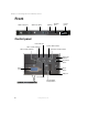
Chapter 1: Checking Out Your Gateway Server Front SCSI hard drive 1 SCSI hard drive 2 CD drive Diskette drive Control panel Control panel Power indicator LAN 1 activity indicator System fault indicator Hard drive activity indicator LAN 2 activity indicator System ID indicator System ID button VGA port Reset button USB port Power button Non-maskable interrupt button 2 www.gateway.
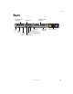
Back Back Low-profile PCI expansion USB port Full-height PCI expansion LAN 2 jack USB port VGA port Serial RJ-45 port External SCSI System ID indicator Power connector PS/2 mouse/keyboard port LAN 1 jack www.gateway.
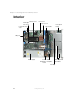
Chapter 1: Checking Out Your Gateway Server Interior Memory slots Full-height riser card Processor 1 Processor 2 Fan module Low-profile riser card Front panel board I/O ports Power supply Power SCSI distribution backplane board Flex bay 4 www.gateway.
System board System board Connectors PCI riser card (low-profile) Auxiliary power SCSI Fan module power PCI riser card (full-height) Front panel USB www.gateway.
Chapter 1: Checking Out Your Gateway Server Getting Help In addition to your operating system’s documentation, you can use the following information resources to help you use your server. Server Companion CD Use the Server Companion CD to access file utilities, Windows 2000 Server drivers, and documentation for your server and its components. For more information, see Using Your Server Companion CD. Gateway Web site Gateway provides a variety of information on its Web site to help you use your server.
Setting Up Your Server 2 Read this chapter to learn how to: ■ Use your server safely ■ Install your server into a cabinet ■ Start and turn off your server ■ Set up your operating system 7
Chapter 2: Setting Up Your Server Setting up the hardware To make sure that your working environment is safe: ■ Use a clean, dry, flat, stable surface for your server. Allow at least 6 inches at the rear of the server for cabling and air circulation. ■ Use the instructions on your server’s setup poster to set up your hardware. ■ Use a grounded (three-prong) surge protector. A surge protector helps protect against AC power fluctuations.
Protecting from power source problems Protecting from power source problems Surge protectors, line conditioners, and uninterruptible power supplies can help protect your server against power source problems. Surge protectors During a power surge, the voltage level of electricity coming into your server can increase to far above normal levels and cause data loss or server damage.
Chapter 2: Setting Up Your Server Line conditioners A line conditioner protects your server from the small fluctuations in voltage from an electrical supply. Most servers can handle this variation, called line noise, without problems. However, some electrical sources include more line noise than normal. Line noise can also be a problem if your server is located near, or shares a circuit with, a device that causes electromagnetic interference, such as a television or a motor.
Mounting your server into a cabinet Mounting your server into a cabinet The cabinet mounting hardware included with your server should be used with standard 4-post cabinets that have front and back vertical posts. The L-shaped cabinet mounting brackets can be used for mid-mounting on a 2-post cabinet, but that procedure is not covered here. If your cabinet is a different type, obtain mounting hardware from the cabinet manufacturer.
Chapter 2: Setting Up Your Server To mount your server in a cabinet: 1 Remove the two screws from each handle, then set the handles and screws aside. Screws 2 12 Align the holes in a server rail with the tabs on the side of the server, then place the rail against the server and slide the rail as far forward as it will go. Both server rails are identical, so you can use either rail on either side of the server. www.gateway.
Mounting your server into a cabinet 3 Use one of the small screws to fasten the rail to the server, then attach the remaining rail to the other side of the server. Screw 4 Place a disk guide over the disk guide screw hole towards the back of the server. Screw hole www.gateway.
Chapter 2: Setting Up Your Server 5 Insert a small screw through the disk guide and tighten the screw. Attach the remaining disk guide to the other side of the server. Screw 6 14 Attach a nut bar to the inside of the two rear cabinet posts using medium screws, but do not completely tighten the screws (leave them loose enough to allow insertion of the cabinet rail in the next step). www.gateway.
Mounting your server into a cabinet 7 Insert the slotted foot of a cabinet rail between each nut bar and post, then tighten the screws. Warning Lifting the server and attaching it to the rack is a two-person job. If needed, use an appropriate lifting device. A fully loaded Gateway 955 server weighs about 30 lbs. (13.6 kg). 8 With the front of the server facing you, lift the server, insert it into the cabinet from the front, then position the disk guides so they fit in the cabinet rails.
Chapter 2: Setting Up Your Server 10 Attach one of the server rails to the front cabinet post using two of the medium screws and one nut bar, then attach the remaining rail to the other cabinet post. Warning 16 Screws are required to support the front of the server. You must support the server while installing or removing the front screws and while sliding the server on or off the cabinet rails. www.gateway.
Mounting your server into a cabinet Installing the front cover Important The front cover is held in place by the server handles. If you are not installing the front cover, you do not need to install the handles. To install the front cover (optional): 1 Insert one of the large screws into the front screw hole on the handle, then insert a spacer onto the part of the screw protruding from the back of the handle.
Chapter 2: Setting Up Your Server 18 3 Align the screw on the handle with the center hole in the server rail, then tighten the screw. 4 5 Attach the remaining handle to the other side of the server. Remove the front cover lock keys from the inside of the front cover, then snap on the front cover. www.gateway.
Mounting your server into a cabinet 6 To lock the front cover, insert the key into the lock and rotate it ¼ turn clockwise. To unlock it, rotate the key ¼ turn counter-clockwise. Lock Unlock Removing the server from a cabinet To remove the server from a cabinet: Warning Screws are required to support the front of the server. You must support the server while removing the front screws and while sliding the server off the cabinet rails. 1 2 3 Remove the front cover, if installed.
Chapter 2: Setting Up Your Server Starting your server Before you start your server for the first time: ■ Make sure that the server and monitor are plugged into a power outlet or surge protector and that the surge protector (if you are using one) is turned on. ■ Make sure that all cables are connected securely to the correct ports and jacks on the back of the server.
Starting your server When the power indicator is... It means... Green (steady on) The server is turned on. Green (blinking) The server is in sleep mode. Off The server is turned off. When the system fault indicator is... It means... Green (steady on) The server is operating normally. Green (blinking) The server is operating in a degraded condition. Orange (steady on) The server is in a critical or unrecoverable condition. Orange (blinking) The server is in a noncritical condition.
Chapter 2: Setting Up Your Server Understanding the power-on self-test When you turn on your server, the power-on self-test (POST) routine checks the server memory and components. If POST finds any problems, the server displays error messages. Write down any error messages that you see, then see “Error messages” on page 100 and “Beep codes” on page 103 for troubleshooting information. Turning off your server Every time you turn off your server, first shut down the operating system.
Setting up the operating system Setting up the operating system If you ordered your server with the operating system already installed by Gateway, it is completely installed and the basic settings are already configured. See your operating system’s documentation for instructions on configuring advanced settings for your specific network. If you are installing an operating system because it was not already installed by Gateway, see the appropriate installation guide for instructions. www.gateway.
Chapter 2: Setting Up Your Server 24 www.gateway.
Maintaining Your Server 3 Read this chapter to learn how to: ■ Care for your server ■ Record the BIOS configuration ■ Manage your server and network 25
Chapter 3: Maintaining Your Server Caring for your server To extend the life of your server: ■ Be careful not to bump or drop your server. ■ When transporting your server, we recommend that you put it in the original packaging materials. ■ Keep your server and magnetic media away from equipment that generates magnetic fields, such as unshielded speakers. ■ Avoid subjecting your server to extreme temperatures. Do not expose your server to heating ducts or other heat-generating objects.
Caring for your server Cleaning tips ■ Always turn off your server and other peripheral devices before cleaning any components. Warning When you shut down your server, the power turns off, but some electrical current still flows through your server. To avoid possible injury from electrical shock, unplug the power cord and all other cables connected to the server. ■ Use a damp, lint-free cloth to clean your server and other parts of your server system.
Chapter 3: Maintaining Your Server Preparing for system recovery If your system files are corrupted, you may not be able to start the server from the hard drive. Startup diskettes are diskettes that let you start the server and attempt to fix the problem. See your operating system’s documentation or online help for instructions on creating startup diskettes. Some operating systems also let you create an emergency repair diskette to back up critical operating system files.
System administration System administration Gateway Server Manager Gateway Server Manager lets you manage multiple computers on a Windows™ network from a single window, then implement commands and policies across the network with a single action. With Gateway Server Manager, you can run system management tasks which are triggered by certain events or conditions. Printed documentation comes with the Gateway Server Manager CD. You can find additional documentation in the program’s online help.
Chapter 3: Maintaining Your Server Using BIOS security passwords To prevent unauthorized use of the server, you can set server startup passwords. Set up an administrator password to prevent unauthorized access to the BIOS Setup utility. For information about resetting BIOS passwords, see “Resetting BIOS passwords” on page 93. To set the BIOS security passwords: 1 Restart your server, then press F2 when the Gateway logo screen appears during startup. The BIOS Setup utility opens.
Using your Server Companion CD Using your Server Companion CD You can use your Server Companion CD to: ■ Install hardware drivers ■ Install programs ■ View server documentation Instructions for using the CD are provided in Using Your Server Companion CD. www.gateway.
Chapter 3: Maintaining Your Server Identifying your server While you are working on a cabinet that contains several slim servers, it can be difficult to keep track of which server or servers you are currently working on. The System ID indicator is a blue LED that you can turn on to help you locate the correct server. Your server has a System ID indicator in the front and in the back. To turn on the System ID indicator: 1 Press the System ID button. The two blue System ID indicators turn on.
Updating the baseboard management controller firmware Updating the baseboard management controller firmware The baseboard management controller (BMC) performs several system management functions such as: ■ Monitoring server components and sensors ■ Managing nonvolatile storage for the system event log and sensor data records ■ Interfacing with the emergency management port (RJ-45 serial on back panel) and LAN 1 port to send alerts and interact with remote management systems.
Chapter 3: Maintaining Your Server To update the BMC firmware: 1 Follow the instructions in “Preventing static electricity discharge” on page 45. Make sure that you disconnect the power cord, and wait until the Standby power LED turns off. Caution If you do not disconnect the power cord when instructed to in this procedure, the BMC firmware will not update. Pins 1-2 Standby power LED 34 2 3 4 Follow the instructions in “Opening the server case” on page 46. 5 Create a DOS-bootable diskette.
Updating the baseboard management controller firmware 6 7 8 9 10 Download the BMC update file from support.gateway.com. Follow the instructions included with the update file. Turn off the server, then disconnect the power cord and wait for the Standby power LED to turn off. Follow the instructions in “Opening the server case” on page 46. Move the BMC Write Enable jumper back to pins 2-3. Pins 2-3 11 Follow the instructions in “Closing the server case” on page 48, then reconnect the power cord. www.
Chapter 3: Maintaining Your Server Using the System Setup Utility The System Setup Utility (SSU) lets you: ■ View FRU information ■ View sensor data records ■ Set up the server to send alerts for platform events ■ Set up the server for out-of-band (OOB) access through Gateway Server Manager Important The SSU does not work within a DOS window running under an operating system such as Windows.
Using the System Setup Utility Viewing sensor data records To view the Sensor Data Records (SDR): 1 Boot your server from the Server Companion CD, then select System Setup Utility from the menu. The System Setup Utility starts. 2 3 In the SSU Main window, click SDR Manager. 4 Click an SDR. Information for that SDR is displayed. Click a category in the left pane. The category expands to show a list of SDRs for that category.
Chapter 3: Maintaining Your Server 5 Click the remote access mode from the LAN Access Mode list: ■ Always Available—A remote system can initiate a LAN connection regardless of the state of the server. ■ Restricted—A remote system can initiate a LAN connection, but cannot perform control operations such as turn off power, reset, or front panel NMI (non-maskable interrupt). ■ Disabled—Remote systems are not allowed to initiate LAN connections.
Using the System Setup Utility 4 To require a password for remote access, type the password in the Enter New Password box and in the Verify New Password box. Passwords can be from 1 to 16 characters long, using any ASCII character in the range 32-126. To clear the password, leave both boxes blank. You can also clear the password by clicking Options, then Clear LAN Password. 5 In the Modem Ring Time box, type the number of 500 ms intervals that the BMC should wait before answering an incoming call.
Chapter 3: Maintaining Your Server Setting up paging alerts To set up paging alerts: 1 Boot your server from the Server Companion CD, then select System Setup Utility from the menu. The System Setup Utility starts. 2 Install an external modem on the serial RJ-45 port on the back of your server. 3 4 5 In the SSU Main window, click Platform Event Manager (PEM). In the PEM window, click Configure EMP.
Using the System Setup Utility 11 In the Paging String box, type the telephone number to dial for the page and the message you want sent with the page. The maximum length for the paging string is determined at runtime from firmware. You will be notified if the string is truncated. Following a save, the actual string saved is displayed in the edit box. 12 13 Click Options, then click Configure Event Actions.
Chapter 3: Maintaining Your Server 5 In the SNMP Community String box, you can type an optional string for the community field in the Header section of the SNMP trap sent for an alert. The string must be from 5 to 16 characters. The default string is public. 6 In the IP Setup box, click either: ■ DHCP—The IP address for the server is automatically assigned by the DHCP (dynamic host control protocol) server on the network. The Host, Gateway, and Subnet Mask boxes in the dialog box are ignored.
Installing Components 4 Read this chapter to learn how to: ■ Open and close the server case ■ Install drives ■ Install expansion cards and memory modules ■ Install processors ■ Replace the power supply ■ Replace the SCSI backplane ■ Replace the fan module ■ Replace the front panel board and power distribution board ■ Replace the system board and CMOS battery You must open your server case to install components.
Chapter 4: Installing Components Preparing to install components Selecting a place to work Work on your server in an area that: ■ Is clean (avoid dusty areas) ■ Is a low-static environment (avoid carpeted areas) ■ Has a stable surface on which to set your server ■ Has enough room to place all of your server parts ■ Is near a grounded outlet so you can test your server after installation ■ Is near a telephone (in case you need help from Gateway Technical Support).
Preventing static electricity discharge Preventing static electricity discharge The components inside your server are extremely sensitive to static electricity, also known as electrostatic discharge (ESD). Warning ESD can permanently damage electrostatic discharge-sensitive components in the server. Prevent ESD damage by following ESD guidelines every time you open the server case.
Chapter 4: Installing Components Opening the server case Because the components inside your server are extremely sensitive to static electricity, make sure that you follow the instructions at the beginning of this chapter to avoid static electricity damage. Warning For correct cooling and air flow, always reinstall the top panel before you turn on the server. Operating the server without the panel in place will cause the server to overheat.
Opening the server case 5 Press and hold the panel release button, then slide the top panel toward the back of the server about 1/2 inch. Panel release button 6 Lift the top panel away from the server. www.gateway.
Chapter 4: Installing Components Closing the server case To close the server case: 48 1 Make sure that all of the internal cables are arranged inside the case so they will not be pinched when you close the case. 2 3 4 Slide the top panel’s edges into the server. Slide the top panel toward the front of the server until it clicks into place. Reconnect the power cord and all other cables. www.gateway.
Installing drives Installing drives Your server’s basic configuration includes one combination CD/diskette drive and as many as three SCSI hard drives. As you prepare to install drives, remember: ■ Before you install a drive, see the drive’s documentation for information on configuring the drive, setting drive jumpers, and attaching cables. ■ You may need to configure the drives you install using the BIOS Setup utility. Press F2 at startup to open the BIOS Setup utility.
Chapter 4: Installing Components 50 3 While holding the locking handle, pull the drive out of the server. 4 Insert the new drive into the Flex Bay, then press it in until the drive faceplate is flush with the front of the server. 5 6 Rotate the locking handle down. Reconnect all power cords and peripheral device cables, then turn on the server. www.gateway.
Installing drives Installing a hot-swap SCSI hard drive into the Flex Bay To install a hot-swap hard drive into the Flex Bay: 1 Follow the instructions in “Preventing static electricity discharge” on page 45. 2 Rotate the combination drive’s locking handle up. 3 While holding the locking handle, pull the drive out of the server. www.gateway.
Chapter 4: Installing Components 52 4 Insert the Flex Bay plug into the top left area of the front control panel. The Flex Bay plug comes in your server’s accessory box. 5 Install the hard drive into the hot-swap drive tray. For instructions, see “Installing a hard drive” on page 54. 6 Make sure that the tray’s release lever is fully open, then slide the tray and drive into the Flex Bay. www.gateway.
Installing drives 7 8 Press the lever closed to lock the drive into place. Reconnect all power cords and peripheral device cables, then turn on the server. After the hard drive is installed and the server is turned on, the hard drive in the Flex Bay is hot-swappable. www.gateway.
Chapter 4: Installing Components Installing a hard drive Use this procedure to add or replace hard drives in the hot-swap bay. Your server supports up to three 1-inch high 3.5-inch SCA SCSI hard drives. You can purchase additional SCSI drives through your Gateway sales or Technical Support representative. Important Gateway tests and verifies the operation and compatibility of the drives it sells.
Installing drives 2 Press the green release button on the hot-swap tray lever, then swing the lever open all the way. 3 Pull the tray straight out of the server. www.gateway.
Chapter 4: Installing Components 4 If you are replacing a hard drive, remove the four screws that secure the old hard drive to the drive tray, then remove the drive from the tray. Screw Screw Screw Screw - OR If you are adding a new drive, remove the four screws that secure the hard drive spacer to the drive tray, then remove the spacer from the tray. Screw Screw Screw Screw 56 www.gateway.
Installing drives 5 Line up the screw holes in the new drive with the holes in the side of the drive tray, then secure the drive to the tray with the four screws you removed in Step 4. 6 Make sure that the tray’s release lever is open, then slide the new drive into the empty hot-swap bay. 7 Close the drive’s release lever. www.gateway.
Chapter 4: Installing Components Installing memory Modules must be installed in identical pairs. Use only low-profile (LP) 1.2-inch, DDR-266 compliant, SDRAM registered ECC, DIMM memory modules. First install modules into Bank 1, then Bank 2, then Bank 3. Supports up to 12 GB total memory. Caution Modules must be installed in identical pairs. Use only low-profile (LP) 1.2-inch, DDR-266 compliant, SDRAM registered ECC, DIMM memory modules. Install memory first into Bank 1, Bank 2, then Bank 3.
Installing memory To install or replace memory: 1 Follow the instructions in “Preventing static electricity discharge” on page 45. 2 3 Follow the instructions in “Opening the server case” on page 46. 4 Align the notch on the new module with the notch in the memory module slot and press the module firmly into the slot. The tabs on the sides of the memory slot should secure the memory module automatically. 5 6 Follow the instructions in “Closing the server case” on page 48.
Chapter 4: Installing Components Installing PCI expansion cards Full-height riser card Low-profile riser card To replace, add, or reseat a PCI expansion card: 60 1 Follow the instructions in “Preventing static electricity discharge” on page 45. 2 3 Follow the instructions in “Opening the server case” on page 46. If you are replacing a card, disconnect any cables that are attached to the old card. www.gateway.
Installing PCI expansion cards 4 Locate the appropriate riser card, then lift the riser card from the system board by lifting the blue plastic loop and the end of the riser card closest to the front of the server. 5 Pull the card locking clip open, then swing the locking clip away from the riser card. 6 If you are replacing a card, remove the old expansion card. You can slightly seesaw the card end-to-end to loosen the card, but do not bend the card sideways.
Chapter 4: Installing Components 62 7 If this is the first time the slot will be used for an expansion card, remove the slot’s EMI shield from the riser card by pushing it toward the back of the riser card. 8 Insert the new card into the card slot. You can slightly seesaw the card end-to-end to help insert the card, but do not bend the card sideways. www.gateway.
Installing PCI expansion cards 9 Rotate the card locking clip closed. 10 Connect any cables to the card following the instructions in the card’s documentation. 11 12 13 Press the riser card back into the server. Follow the instructions in “Closing the server case” on page 48. See the card’s documentation for software installation instructions. www.gateway.
Chapter 4: Installing Components Replacing the fan module To replace the fan module: 64 1 Follow the instructions in “Preventing static electricity discharge” on page 45. 2 3 Follow the instructions in “Opening the server case” on page 46. 4 Unplug the fan module’s power cable from the system board. Lift the air baffle away from the server. www.gateway.
Replacing the fan module 5 Press the module’s release button, then lift the module away from the server. 6 Insert one end of the new fan module under the module guide located on the right side of the case near the processors. Fan module guide www.gateway.
Chapter 4: Installing Components 7 Press the module down until it clicks into place, then plug the fan module’s power cable into the system board. 8 Insert the air baffle’s mounting post into the mounting post hole. Make sure that the data cable is routed under the baffle. Air baffle mounting post hole 9 66 Follow the instructions in “Closing the server case” on page 48. www.gateway.
Installing a processor Installing a processor The server is compatible with Intel® Xeon processors. The server automatically detects the processors each time you turn on the server. Whenever you install new processors, you should first install the most current version of the BIOS. For instructions, see “Updating the BIOS” on page 91. Important You must have a processor in the Processor 1 socket, or your server will not start.
Chapter 4: Installing Components 68 4 Lift the transparent air duct away from the processor sockets. 5 Remove the fan module. For instructions, see “Replacing the fan module” on page 64. 6 Press down on the heat sink locking clip’s lever to detach the clip on the lever’s side, then slide the clip toward the opposite end and remove it from the heat sink. www.gateway.
Installing a processor 7 8 Remove the remaining clip. Remove the heat sink. Important 9 The heat sink mounting paste may harden over time and hold the heat sink securely to the processor. If removing the heat sink also pulls the processor out of the processor socket, the processor should still be undamaged. Continue with the procedure. Rotate the processor release lever a full 135° to release the processor, then lift the processor out of the socket. www.gateway.
Chapter 4: Installing Components 10 If you are installing a processor into an empty processor socket that has an air dam installed, pinch the sides of the air dam together and lift it away from the socket.
Replacing the power supply Replacing the power supply Warning The power supply in this server contains no user-serviceable parts. Only a qualified computer technician should service the power supply. Your server comes with a 3-wire AC power cord fitted with the correct plug style for your region. If this plug does not match the connector on your surge protector, UPS, or wall outlet, do not attempt to modify the plug in any way.
Chapter 4: Installing Components 4 72 Slide the power supply toward the back of the server until the power supply disconnects from the server. www.gateway.
Replacing the power supply 5 Lift the power supply out of the case. 6 Lay the new power supply onto the metal tabs, then slide it toward the front of the server until the back of the power supply is secured behind the metal tabs. 7 Follow the instructions in “Closing the server case” on page 48. www.gateway.
Chapter 4: Installing Components Replacing the SCSI backplane To replace the SCSI backplane: 74 1 Follow the instructions in “Preventing static electricity discharge” on page 45. 2 3 Follow the instructions in “Opening the server case” on page 46. 4 Remove the fan module. For instructions, see “Replacing the fan module” on page 64. 5 Remove the cables from the backplane board, then remove the thumbscrew.
Replacing the SCSI backplane 6 Slide the backplane about 1/8 inch to the right, then lift it away from the server. 7 Align the new backplane’s keyhole slots with the mounting posts on the floor of the server case, then slide the backplane 1/8 inch to the left. Keyhole slot mounting post 8 Install the thumbscrew to secure the backplane to the server, then reattach the cables you removed in Step 5. www.gateway.
Chapter 4: Installing Components 9 10 11 76 Install the drives back into the server. Make sure that you replace the drives in the same bays you removed them from in Step 3. Reinstall the fan module. Follow the instructions in “Closing the server case” on page 48. www.gateway.
Replacing the CMOS battery Replacing the CMOS battery If the server clock does not keep time or the settings in the BIOS Setup utility are not saved when you turn off the server, replace the CMOS battery with an equivalent battery. Warning Danger of explosion if battery is incorrectly replaced. Replace only with the same or equivalent type recommended by the manufacturer. Dispose of or recycle used batteries by taking them to a hazardous waste facility.
Chapter 4: Installing Components 6 Locate the old battery on the system board and note its orientation. You will need to install the new battery the same way. CMOS battery 78 7 Push the battery retention clip away from the battery until the battery lifts up, then remove the old battery. You can use a screwdriver to help lift the battery. 8 Make sure that the positive (+) side of the new battery is facing up, then press the new battery into the socket until it snaps into place.
Replacing the power distribution board Replacing the power distribution board 1 Follow the instructions in “Preventing static electricity discharge” on page 45. 2 3 Follow the instructions in “Opening the server case” on page 46. Remove each of the drives from server, including any drive in the Flex Bay. For instructions, see “Installing a hard drive” on page 54 and “Replacing the CD/diskette drive in the Flex Bay” on page 49. 4 Remove the power supply.
Chapter 4: Installing Components 8 Pull the power distribution board toward the front of your server until it disconnects from the system board. 9 Plug the new power distribution board into the system board, then reconnect the power distribution board cables. 10 11 12 13 80 Reinstall the SCSI backplane, then reinstall the power supply. Reinstall the air baffle and fan module. Reinstall the drives. Follow the instructions in “Closing the server case” on page 48. www.gateway.
Replacing the front panel board Replacing the front panel board 1 Follow the instructions in “Preventing static electricity discharge” on page 45. 2 3 Follow the instructions in “Opening the server case” on page 46. Remove the two cables from the front panel board, then remove the thumbscrew. www.gateway.
Chapter 4: Installing Components 4 82 Lift the back of the board 1/8 inch, then pull it toward the back of your server. www.gateway.
Replacing the front panel board 5 Insert the new front panel board so the light pipes align with their corresponding holes in the front panel. Warning Forcing the board into place without carefully guiding the light pipes into their holes will damage the light pipes. Light pipes 6 Install the thumbscrew to secure the board to the server, then reconnect the cables. 7 Follow the instructions in “Closing the server case” on page 48. www.gateway.
Chapter 4: Installing Components Replacing the system board To replace the system board: 84 1 Follow the instructions in “Preventing static electricity discharge” on page 45. 2 3 Follow the instructions in “Opening the server case” on page 46. 4 Remove the riser cards. For instructions, see “Installing PCI expansion cards” on page 60. 5 Remove the fan module. For instructions, see “Replacing the fan module” on page 64. 6 Remove the heat sinks and processors.
Replacing the system board 8 Remove the three screws that secure the system board to the server. Screws 9 Remove the eight screws that secure the heat sink brackets to the system board, then remove the brackets. Screws Screws Screws Screws www.gateway.
Chapter 4: Installing Components 10 Slide the system board toward the front of the server. If the board is difficult to move, push on the rear I/O port panel for added leverage. 11 12 Lift the board away from the case. Insert the new system board into the case, then slide the board toward the back of the case so the board is held under the system board guides. Guide 86 www.gateway.
Replacing the system board 13 14 15 16 Replace the three system board screws you removed in Step 8. 17 18 Follow the instructions in “Closing the server case” on page 48. 19 Check BIOS settings to make sure that they detect the server’s new hardware, then save your changes (if any) and close the BIOS Setup utility. 20 If your server does not start after installing the new system board, contact Technical Support. For more information, see “Getting Help” on page 6. Reinstall the heat sink brackets.
Chapter 4: Installing Components 88 www.gateway.
Using the BIOS Setup Utility 5 Read this chapter to learn how to: ■ Open the BIOS Setup utility ■ Update the BIOS ■ Reset the BIOS settings to their factory defaults ■ Reset the BIOS passwords 89
Chapter 5: Using the BIOS Setup Utility Opening the BIOS Setup utility The BIOS Setup utility stores basic settings for your server. These settings include basic hardware configuration, resource settings, and password security. These settings are stored and saved even when the power is off. Caution The options in the BIOS Setup utility have been set at the factory for optimal performance. Changes to these settings will affect the performance of your server.
Updating the BIOS Updating the BIOS If you need a new version of the BIOS, you can download the BIOS update from Gateway, then install the new version from a diskette. To update the BIOS: 1 2 3 4 5 6 Print the appendix for “BIOS Settings” on page 119. Restart your server, then press F2 when the Gateway logo screen appears during startup. Record any custom BIOS settings on your printout. Download the BIOS update from support.gateway.com. Follow the instructions in the self-extracting BIOS update file.
Chapter 5: Using the BIOS Setup Utility Resetting the BIOS You can use two methods to clear all BIOS Setup settings and return them to the factory defaults: ■ Press the power and reset buttons on the front of the server. ■ Move the Clear BIOS jumper on the system board. To reset the BIOS using the power and reset buttons: 1 2 Print the appendix for BIOS Settings in this guide. Restart your server, then press F2 when the Gateway logo screen appears during startup.
Resetting the BIOS Warning 7 Moving the jumper while the power is on can damage your server. Always turn off the server and unplug the power cord and all other cables before changing the jumper. Place a jumper across the CLR/CMOS pins of jumper J1D4, then remove the jumper. The BIOS settings are cleared. CLR/CMOS (clear BIOS) pins 8 Follow the instructions in “Closing the server case” on page 48. Resetting BIOS passwords To reset BIOS passwords, you must reset and clear all BIOS settings.
Chapter 5: Using the BIOS Setup Utility 94 www.gateway.
Troubleshooting 6 Read this chapter to learn how to: ■ Get telephone support and training ■ Interpret error messages and codes ■ Troubleshoot If the suggestions in this chapter do not correct the problem, see “Telephone support” on page 96 for more information about how to get help.
Chapter 6: Troubleshooting Telephone support Before calling Gateway Technical Support If you have a technical problem with your server, follow these recommendations before contacting Gateway Technical Support: 96 ■ Make sure that your server is connected correctly to a grounded AC outlet that is supplying power. ■ If a peripheral device, such as a keyboard or mouse, does not appear to work, make sure that all cables are plugged in securely and plugged into the correct port or jack.
Telephone support Telephone support Gateway offers a wide range of customer service, technical support, and information services. Telephone numbers You can access the following services through your telephone to get answers to your questions: Resource Service description How to reach Fax on demand support Order a catalog of documents on common problems, then order documents by document numbers. The documents will be faxed to you.
Chapter 6: Troubleshooting Tutoring and training Gateway's Technical Support professionals cannot provide hardware and software training. Instead, Gateway recommends the following training resources. Resource Service description For more information In-store training at Gateway stores Our friendly and knowledgeable software trainers can teach you how to use the Internet and the most popular software programs, including Microsoft Word, Excel, and PowerPoint. www.gateway.
Safety guidelines Safety guidelines While troubleshooting your server, follow these safety guidelines: ■ Never remove the top panel while your server is turned on and while the modem cable and the power cord is connected. ■ Do not attempt to open the monitor. To do so is extremely dangerous. Even if the power is disconnected, energy stored in the monitor components can be dangerous. Also, opening the monitor voids its warranty. ■ Make sure that you are grounded correctly before opening the server.
Chapter 6: Troubleshooting Error messages These messages often indicate procedural errors such as typing an incorrect keystroke or trying to save a file to a write-protected diskette. Some messages, however, may indicate a problem that requires further troubleshooting. Diskette drive 0 seek to track 0 failed ■ Restart your server, then open the BIOS Setup utility by pressing and holding F2 while your server restarts. Make sure that the drive settings are correct.
Error messages Invalid partition table ■ The master boot record may be corrupt. For troubleshooting information, see “The master boot record is corrupted” on page 107. Invalid password ■ Enter your password again. Some passwords are case sensitive. ■ If you do not know the password, you may need to reinstall the software you are trying to access. ■ System startup passwords are stored in BIOS.
Chapter 6: Troubleshooting Troubleshooting First steps Try these steps first before going to the following sections: ■ Make sure that the power cord is connected to your server and an AC outlet and that the AC outlet is supplying power. ■ If you use a surge protector or a UPS, make sure that it is turned on and is rated to handle the power required by your server.
Troubleshooting Battery replacement If you have problems after installing a new CMOS battery, try each of the following items, closing the case and restarting the server after each try: ■ Restart your server, then open the BIOS Setup utility by pressing and holding F2 while your server restarts. Correct any discrepancies. ■ Remove the top panel by following the instructions in “Opening the server case” on page 46, then make sure that all cables inside the case are attached securely.
Chapter 6: Troubleshooting Beeps Description Troubleshooting steps 1 The memory refresh circuitry on the system board is faulty. Reseat the memory or replace with modules you know are good. 2 Parity cannot be reset. Same as for 1 beep. 3 Base memory test failure. Same as for 1 beep. 4 System timer is not operational. Remove all expansion cards. ■ ■ 5 Processor failure detected.
Troubleshooting BIOS The settings in the BIOS Setup utility are not retained ■ Replace the CMOS battery. For instructions, see “Replacing the CMOS battery” on page 77. CD drive Your server does not recognize a CD or the CD drive ■ Restart your server, then open the BIOS Setup utility by pressing and holding F2 while your server restarts. Make sure that the IDE controllers are enabled. For more information, see “Using the BIOS Setup Utility” on page 89. ■ Reinstall the device driver.
Chapter 6: Troubleshooting The diskette drive LED is lit continuously ■ Remove the diskette from the drive. If the light stays on, try restarting your server. ■ Turn off your server, then remove the combination drive and push it in again to make sure the drive is seated correctly. For instructions, see “Replacing the CD/diskette drive in the Flex Bay” on page 49. Expansion cards Your server does not recognize an expansion card ■ Restart your server.
Troubleshooting Your server does not recognize a SCSI drive ■ Make sure that the SCSI controller is enabled in the BIOS Setup utility. ■ Reinstall the device driver. For instructions, see Using Your Server Companion CD. ■ Change the drive’s SCSI address to one that is not being used by your server. For more information about SCSI device configurations, see your drive’s documentation. ■ Run SCSI Verify in the SCSI BIOS.
Chapter 6: Troubleshooting Keyboard Liquid has been spilled into the keyboard ■ If you spilled liquid in the keyboard, turn off your server and unplug the keyboard. Clean the keyboard and turn it upside down to drain it. Let the keyboard dry before using it again. If the keyboard does not work after it dries, you may need to replace it. This type of damage is not covered by your server’s warranty.
Troubleshooting To check the dialing properties in Windows: 1 In Windows 2000 Server, click Start, Settings, then click Control Panel. The Control Panel window opens. - OR In Windows Server 2003, click Start, then click Control Panel. The Control Panel window opens. 2 Click/Double-click the Modems icon, then click Dialing Properties. The Dialing Properties dialog box opens. 3 Make sure that all settings are correct. ■ Make sure that you are not using a digital, rollover, or PBX line.
Chapter 6: Troubleshooting If your system has a v.90 modem, the speed at which you can upload (send) data is limited to 33.6K. If your system has a v.92 modem, the speed at which you can upload data is limited to 48K. Your ISP may not support 48K uploads. The modem is not recognized by your server ■ If the modem shares the telephone line with another device, make sure that the telephone line is not in use (for example, someone is on the telephone, or another modem is in use).
Troubleshooting A horizontal line or wire is visible across the monitor screen The monitor may use thin damper wires, located approximately 1/3 of the way from the upper and lower screen edges, to stabilize the internal aperture grille. These wires are most obvious when the monitor displays a white background. The aperture grille allows more light to pass through the screen for brighter colors and greater luminescence.
Chapter 6: Troubleshooting 112 www.gateway.
Server Specifications A The following specifications are for the standard configuration. Your server may contain optional equipment. All specifications are subject to change.
Appendix A: System specifications Case size 24.25 × 17 × 11/16 inches (61.6 × 43.2 × 1.75 cm) (without handles) Weight Varies by configuration. A fully loaded server weighs about 30 lbs. (13.6 kg) Fans One fan module, containing five 40 mm fans Ports ■ ■ ■ ■ ■ ■ Drives (standard) One drive module contains: ■ ■ 3.
System board specifications System board specifications Processor Dual socket 604 package 533 MHz system bus Supports as many as two Intel Xeon CPUs Chipset Intel E7501 ■ ■ ■ Memory ■ ■ PCI device/slot ■ ■ ■ ■ ■ ■ ■ SCSI ■ ■ ■ ACPI One full-length, full-height 64-bit PCI riser One low-profile (LP) 64-bit PCI riser On-board ATI Rage XL ■ LAN Six DIMM slots support from 256 MB to 12 GB total memory Use only low-profile (LP) 1.
Appendix A: Environmental specifications The following specifications identify maximum environmental conditions. At no time should the server run under conditions which violate these specifications. Variable Requirements Temperature Maximum rate of change: 18°F (10°C) per hour Nonoperating: -55° to 150°F (-48.3° to 65.5°C) Operating: 41° to 95°F (5° to 35°C); derated 0.9°F (0.5°C) for every 1,000 feet (305 meters).
Additional specifications Additional specifications For more information about your server, such as memory size, hard drive size, and processor type, visit Gateway’s eSupport page at support.gateway.com. The eSupport page also has links to additional Gateway documentation and detailed specifications for your own server. www.gateway.
Appendix A: 118 www.gateway.
BIOS Settings B If you ever need to restore your BIOS settings, such as after a system board change, a record of the settings will make the process much easier. You can print this appendix, then record your custom BIOS settings on the printout. Only settings which can be changed are listed. For a complete list of viewable BIOS settings, run the BIOS Setup utility. To view all BIOS settings: 1 Restart your server, then press F2 when the Gateway logo screen appears during startup.
Appendix B: BIOS menu BIOS submenu Setting Main System Time System Date Floppy A Hard Disk Pre-Delay Primary IDE Master Type Primary IDE Slave Type Secondary IDE Master Type Processor Settings Processor Retest Processor Settings Hyper-Threading Technology Language Advanced PCI Configuration USB Function PCI Configuration Onboard NIC Onboard NIC PCI Configuration Onboard NIC Onboard NIC 1 ROM PCI Configuration Onboard NIC Onboard NIC 2 ROM PCI Configuration Onboard SCSI Onboard SCS
BIOS menu BIOS submenu Setting Peripheral Configuration Serial 2 (RJ45) Address Peripheral Configuration Serial 2 (RJ45) Address Peripheral Configuration Diskette Controller Peripheral Configuration Legacy USB Support Peripheral Configuration Front Panel USB Memory Configuration Extended Memory Test Memory Configuration BANK #1 Memory Configuration BANK #2 Memory Configuration BANK #3 Memory Configuration Memory Retest Advanced Chipset Control Wake On Ring Advanced Chipset Control
Appendix B: BIOS menu BIOS submenu Setting Security Set Admin Password Password On Boot (setting available only when user password is set) Fixed Disk Boot Sector Video Blanking (setting available only when user password is set) Power Switch Inhibit NMI Control Server System Management Console Redirection BIOS Redirection Port ACPI Redirection Band Rate Flow Control Terminal Type Serial Port Connector Event Log Configuration Clear All Event Logs Event Log Configuration Event Logging Event Log Conf
BIOS menu BIOS submenu Setting Fault Reslient Booting Hard Disk OS Boot Timeout Fault Reslient Booting PXE OS Boot Timeout Value Assert NMI on PERR Assert NMI on SERR FRB-2 Policy POST Error Pause Boot Monitoring Boot Monitoring Policy Boot Boot Device Priority 1st Boot Device Boot Device Priority 2nd Boot Device Boot Device Priority 3rd Boot Device Boot Device Priority 4th Boot Device Removable Devices 1st ATAPI CDROM Drives 1st ATAPI CDROM www.gateway.
Appendix B: 124 www.gateway.
Safety, Regulatory, and Legal Information C Important safety information Your Gateway system is designed and tested to meet the latest standards for safety of information technology equipment. However, to ensure safe use of this product, it is important that the safety instructions marked on the product and in the documentation are followed. Warning Always follow these instructions to help guard against personal injury and damage to your Gateway system.
Appendix C: ■ The product should be operated only from the type of power source indicated on the rating label. ■ If your computer has a voltage selector switch, make sure that the switch is in the proper position for your area. The voltage selector switch is set at the factory to the correct voltage. ■ Openings in the computer case are provided for ventilation. Do not block or cover these openings.
Regulatory compliance statements United States of America Federal Communications Commission (FCC) Unintentional emitter per FCC Part 15 FCC Part 15 Class A Statement The server is designated as complying with Class A requirements if it bares the following text on the rating label: This device complies with Part 15 of the FCC Rules. Operation is subject to the following two conditions: (1) This device may not cause harmful interference.
Appendix C: If this device causes harm to the telephone network, the telephone company will notify you in advance that temporary discontinuance of service may be required. The telephone company may request that you disconnect the equipment until the problem is resolved. The telephone company may make changes in its facilities, equipment, operations, or procedures that could affect the operation of this equipment.
Canada Industry Canada (IC) Unintentional emitter per ICES-003 This digital apparatus does not exceed the Class A limits for radio noise emissions from digital apparatus as set out in the radio interference regulations of Industry Canada. Le présent appareil numérique n’émet pas de bruits radioélectriques dépassant les limites applicables aux appareils numériques de Classe A prescrites dans le règlement sur le brouillage radioélectrique édicté par Industrie Canada.
Appendix C: Laser safety statement All Gateway systems equipped with CD and DVD drives comply with the appropriate safety standards, including IEC 825. The laser devices in these components are classified as “Class 1 Laser Products” under a US Department of Health and Human Services (DHHS) Radiation Performance Standard. Should the unit ever need servicing, contact an authorized service location.
Notices Copyright © 2003 Gateway, Inc. All Rights Reserved 14303 Gateway Place Poway, CA 92064 USA All Rights Reserved This publication is protected by copyright and all rights are reserved. No part of it may be reproduced or transmitted by any means or in any form, without prior consent in writing from Gateway. The information in this manual has been carefully checked and is believed to be accurate. However, changes are made periodically. These changes are incorporated in newer publication editions.
Appendix C: 132 www.gateway.
Index Numerics 5.
RJ-45 5 SCSI 3, 5 serial 3 USB 2, 3 VGA 2, 3 cover panels removing 46 D DDR SDRAM see memory device drivers installing 31 DIMM see memory diskette drive connector 5 installing 49, 51 location 2 replacing 49, 51 troubleshooting 105 display troubleshooting 110 documentation Gateway Web site 6 Server Companion CD 31 drive bays location 2 drivers installing 31 drives CD 2, 49, 51 configuring 49 diskette 2, 49, 51 hard drive 2, 54 hot-swap 2, 4, 54 installing 49, 51, 54 installing diskette 51 RAID 2, 4, 54 repl
power supply 71 hot-swap drives fan 4, 5 installing 54 location 2 K I L I/O ports 4 IDE connectors 5 drive configuration 49 indicators 2, 3, 21, 32 installing add-in card 60 backplane 74 battery 77 card 60 CD drive 49, 51 diskette drive 49, 51 expansion cards 60 fan module 64 hard drive 54 heat sink 67 hot-swap drive 54 media drive 49, 51 memory 58 PCI card 60 power distribution board 79 power supply 71 processor 67 SCSI backplane 74 SCSI drive 54 system board 84 Internet connection troubleshooting 107
opening case 46 operating system setup 23 power supply installing 71 location 4 manageability connector 5 uninterruptible 10 power-on self-test 22 processor heat sink 67 installing 67 location 4 replacing 67 troubleshooting 111 PS/2 port 3 P R password resetting BIOS 93 supervisor 30 user 30 PCI card see card ports see connections POST (power-on self-test) 22 power auxiliary connector 5 button 2, 20, 22 cord connector 3, 5 indicator 2, 21 LED 2, 21 line conditioners 10 main connector 5 protecting from s
see memory security locking server 29 set passwords 30 setting up in BIOS 30 supervisor password 30 system 29 user passwords 30 using password 30 Security menu BIOS Setup utility 90 security switch connector location 5 serial number 96 serial port 3 Server Companion CD 6, 31 Server menu BIOS Setup utility 90 setting up hardware 8 operating system 23 safety precautions 8, 26, 125 Setup utility see BIOS Setup utility slots memory 5 specifications 114, 117 environmental 116 system board 115 SSU 36 starting ser
modem 108 monitor 110 power 111 power source problems 9 processor 111 safety guidelines 99 SCSI drive 107 technical support 96 telephone support 96 video 110 turning off server 22 turning on server 20 U uninterruptible power supply (UPS) 10 updating BIOS 91 updating the BIOS 91 UPS 10 USB ports internal connector 5 location 2, 3 user password 30 utilities BIOS Setup 89 V VGA port 2, 3 voltage regulator location 5 W Web site Gateway 6 138