Contents 1 Checking Out Your Gateway Server . . . . . . . . . . . . . . . . . . . . . . . . . . . . . 1 Front . . . . . . . . . . . . . . . . . . . . . . . . . . . . . . . . . . . . . . . . . . . . . . . . . . . . . . . . . . . . . Back . . . . . . . . . . . . . . . . . . . . . . . . . . . . . . . . . . . . . . . . . . . . . . . . . . . . . . . . . . . . . . Interior . . . . . . . . . . . . . . . . . . . . . . . . . . . . . . . . . . . . . . . . . . . . . . . . . . . . . . . . . . . . System board . . . . .
Creating an emergency repair diskette . . . . . . . . . . . . . . . . . . . . . . . . . . . . . . .32 Keeping a record of system configuration . . . . . . . . . . . . . . . . . . . . . . . . . . . . .35 System administration . . . . . . . . . . . . . . . . . . . . . . . . . . . . . . . . . . . . . . . . . . . . . . .36 ManageX Event Manager . . . . . . . . . . . . . . . . . . . . . . . . . . . . . . . . . . . . . . . . .36 Server security . . . . . . . . . . . . . . . . . . . . . . . . . . . . . . . . . . .
CD drive . . . . . . . . . . . . . . . . . . . . . . . . . . . . . . . . . . . . . . . . . . . . . . . . . . . . . Cleaning CDs . . . . . . . . . . . . . . . . . . . . . . . . . . . . . . . . . . . . . . . . . . . . . . . . . Diskette drive . . . . . . . . . . . . . . . . . . . . . . . . . . . . . . . . . . . . . . . . . . . . . . . . . Expansion cards . . . . . . . . . . . . . . . . . . . . . . . . . . . . . . . . . . . . . . . . . . . . . . . File management . . . . . . . . . . . . . . . . . . . . . . . .
iv
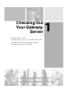
Checking Out Your Gateway Server 1 Read this chapter to learn: ■ Where drives, ports, jacks, and controls are located ■ Where system board components are located ■ What help resources are available 1
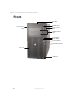
Chapter 1: Checking Out Your Gateway Server Front CD drive Diskette drive Cover release latch Cover release latch Additional drive bays Power button Reset button Power indicator Hard drive indicator Key lock USB ports 2 www.gateway.
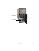
Front Hot-swap drives PCI card fan www.gateway.
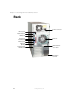
Chapter 1: Checking Out Your Gateway Server Back Power connector Mouse port Keyboard port USB ports Serial port Parallel port Monitor port Rear fan LAN jack (RJ-45) Card retention cover lever System board thumbscrew Kensington lock slot 4 www.gateway.
Interior Interior Cable clip Card retention cover release latch Rear fan SCSI backplane Cable clip Full-length card retention clip RAID bay fan PCI card fan www.gateway.
Chapter 1: Checking Out Your Gateway Server System board Left side Processor 1 Processor 2 Rear fan connector 64-bit PCI card slots 32-bit PCI card slot 6 www.gateway.
System board Right side Power supply manageability connector Auxiliary power connector Processor 1 fan connector Front panel connector SCSI manageability connector Main power connector Voltage regulator slot 1 Memory module slots Voltage regulator slot 2 Diskette drive connector Primary IDE connector Secondary IDE connector Intrusion switch connector SCSI 2 connector SCSI 1 connector Processor 2 fan connector Hot-swap bay fan connector CMOS battery Configuration jumper JP7 PCI card fan connector www.
Chapter 1: Checking Out Your Gateway Server Getting Help In addition to your operating system’s documentation, you can use the following information resources to help you use your server. Server Companion CD Use the Server Companion CD to access file utilities, Windows 2000 Server drivers, and documentation for your server and its components. For more information, see Using Your Server Companion CD.
Setting Up Your Server 2 Read this chapter to learn how to: ■ Use your server safely ■ Start and turn off your server ■ Restart (reboot) your server 9
Chapter 2: Setting Up Your Server Setting up the hardware To make sure that your working environment is safe: ■ Use a clean, dry, flat, stable surface for your server. Allow at least 6 inches at the rear of the server for cabling and air circulation. ■ Use the instructions on your server’s setup poster to set up your hardware. ■ Use a grounded (three-prong) surge protector. A surge protector helps protect against AC power fluctuations.
Protecting from power source problems Protecting from power source problems Surge protectors, line conditioners, and uninterruptible power supplies can help protect your server against power source problems. Surge protectors During a power surge, the voltage level of electricity coming into your server can increase to far above normal levels and cause data loss or server damage.
Chapter 2: Setting Up Your Server Line conditioners A line conditioner protects your server from the small fluctuations in voltage from an electrical supply. Most servers can handle this variation, called line noise, without problems. However, some electrical sources include more line noise than normal. Line noise can also be a problem if your server is located near, or shares a circuit with, a device that causes electromagnetic interference, such as a television or a motor.
Starting your server Starting your server Before you start your server for the first time: ■ Make sure that the server and monitor are plugged into a power outlet or surge protector and that the surge protector (if you are using one) is turned on. ■ Make sure that all cables are connected securely to the correct ports and jacks on the back of the server. Warning When you connect peripheral devices to the server, make sure that your server and devices are turned off and the power cord is unplugged.
Chapter 2: Setting Up Your Server When the power indicator is... It means... Green The server is turned on. Off The server is turned off. If nothing happens when you press the power button: 3 ■ Make sure that the power cord is plugged in securely and that your surge protector (if you are using one) is plugged in and turned on. ■ Make sure that the monitor is connected to the server, plugged into the power outlet or surge protector, and turned on.
Turning off your server Turning off your server Every time you turn off your server, first shut down the operating system. You may lose data if you do not follow the correct procedure. To turn off the server: 1 In Windows 2000 Server, click Start, then click Shut Down. The Shut Down Windows dialog box opens. Click the arrow button to open the What do you want the computer to do list, click Shut down, then click OK.
Chapter 2: Setting Up Your Server Restarting (rebooting) your server If your server does not respond to keyboard or mouse input, you may have to close programs that are not responding. If closing unresponsive programs does not restore your server to normal operation, you may have to restart (reboot) your server. To close unresponsive programs in Windows 2000 Server: 1 Press CTRL+ALT+DELETE, then click Task Manager. A window opens that lets you close a program that is not responding.
Setting up the operating system Setting up the operating system If you ordered your server with the operating system already installed by Gateway, Windows 2000 Server is completely installed and the basic settings are already configured. See your operating system’s documentation for instructions on configuring advanced settings for your specific network.
Chapter 2: Setting Up Your Server 18 www.gateway.
Maintaining Your Server 3 Read this chapter to learn how to: ■ Care for your server ■ Protect your server from viruses ■ Manage hard drive space ■ Clean your server ■ Prepare for system recovery ■ Perform system administration 19
Chapter 3: Maintaining Your Server Caring for your server To extend the life of your server: 20 ■ Be careful not to bump or drop your server, and do not put any objects on top of it. The case, although strong, is not made to support extra weight. ■ When transporting your server, we recommend that you put it in the original packaging materials. ■ Keep your server and magnetic media away from equipment that generates magnetic fields, such as unshielded stereo speakers.
Caring for your server Maintenance task Weekly When needed See...
Chapter 3: Maintaining Your Server Protecting your server from viruses A virus is a program that attaches itself to a file on a computer, then spreads from one computer to another. Viruses can damage data or cause your server to malfunction. Some viruses go undetected for a period of time because they are activated on a certain date. A server that can access the Internet is more likely to get a virus than one that cannot access the Internet.
Managing hard drive space Managing hard drive space Checking hard drive space If your server is running an operating system other than Windows 2000 Server, see the operating system’s documentation for instructions on checking hard drive space. To check hard drive space in Windows 2000 Server: 1 2 Double-click the My Computer icon. Right-click the drive that you want to check for available file space, then click Properties. Drive space information appears. www.gateway.
Chapter 3: Maintaining Your Server Using Disk Cleanup Delete unneeded files, such as temporary Windows files, to free hard drive space. If your server is running an operating system other than Windows 2000 Server, see the operating system’s documentation for instructions on deleting unnecessary files. To use Disk Cleanup in Windows 2000 Server: 1 2 Double-click the My Computer icon. 3 4 Click Disk Cleanup. The Disk Cleanup dialog box opens. 5 Click OK, then click Yes.
Managing hard drive space 3 Click the Tools tab. 4 5 Click Check Now. Click the options to use, then click Start. For help, press F1. Windows checks the drive for errors. This process may take several minutes. 6 Correct any problems that are found by following the on-screen instructions. After Windows has finished checking the drive for errors, it provides a summary of any problems that it may have found. 7 Click OK. www.gateway.
Chapter 3: Maintaining Your Server Defragmenting the hard drive When working with files, your operating system divides the file information into pieces and stores them in different places on the hard drive. This is called fragmentation, and it is normal. In order for your server to use a file, your operating system must search for the pieces of the file and put them back together. This process slows hard drive performance.
Managing hard drive space 3 Click the Tools tab. 4 5 Click Defragment Now. 6 Click Action, then click Defragment. Disk Defragmenter shows its progress on the screen. When finished, Disk Defragmenter asks if you want to quit the program. Click Close. Backing up files Backing up files and removing them from the hard drive frees space for new files on the hard drive. It also protects you from losing important information if the hard drive fails or you accidentally delete files.
Chapter 3: Maintaining Your Server Cleaning your server Keeping your server clean and the vents free from dust helps keep your server performing at its best.
Cleaning your server Cleaning the keyboard You should clean the keyboard occasionally by using an aerosol can of air with a narrow, straw-like extension to remove dust and lint trapped under the keys. If you spill liquid on the keyboard, turn off your server and turn the keyboard upside down. Let the liquid drain, then let the keyboard dry before trying to use it again. If the keyboard does not work after it dries, you may need to replace it.
Chapter 3: Maintaining Your Server Cleaning the mouse If the mouse pointer begins moving erratically across the screen or becomes difficult to control precisely, cleaning the mouse will likely improve its accuracy. If you have an optical mouse, clean the mouse by wiping the bottom of the mouse with a clean cloth. If you have a trackball mouse, follow these instructions. To clean your trackball mouse: 30 1 2 Turn the mouse upside down.
Cleaning your server 4 Clean the mouse rollers with a cotton swab dipped in isopropyl alcohol. Mouse rollers 5 Replace the mouse ball and lock the retaining ring into place. www.gateway.
Chapter 3: Maintaining Your Server Preparing for system recovery You should take precautions that will make it easier to reinstall or repair your operating system if system files become corrupted. These precautions make it easier to restart your server and recover damaged files. Creating startup diskettes If your system files are corrupted, you may not be able to start the server from the hard drive. Startup diskettes are diskettes that let you start the server and attempt to fix the problem.
Preparing for system recovery To create an emergency repair diskette in Windows 2000 Server: 1 Format one 3.5-inch 1.44 MB diskette and insert it into your server’s diskette drive. 2 3 Double-click the My Computer icon. 4 Right-click the C: drive, then click Properties. The Properties dialog box opens. Click the Tools tab. www.gateway.
Chapter 3: Maintaining Your Server 34 5 Click Backup Now. The Backup window opens. 6 Click Emergency Repair Disk. The Emergency Repair Diskette dialog box opens. 7 Click Also back up the registry to the repair directory, then click OK. The files are backed up to the diskette. www.gateway.
Preparing for system recovery Keeping a record of system configuration Recording your operating system configuration Some operating systems let you print a summary of the configuration of your server and the memory allocation. This printed summary can provide information you need to reset your system configuration correctly if the information is lost.
Chapter 3: Maintaining Your Server System administration ManageX Event Manager ManageX lets you manage multiple computers on a Windows 2000 Server or Novell Netware network from a single window, then implement commands and policies across the network with a single action. With ManageX you can run system management tasks which are triggered by certain events or conditions. You can find additional documentation for ManageX Event Manager on the Server Companion CD and the ManageX Event Manager CD.
System administration 3 Select the password to set according to the following table. Option Description Supervisor password To control access to system configuration, set a supervisor password. Using a supervisor password lets you make changes to any setting in the BIOS. Passwords can be cleared. To clear the passwords, see “Resetting BIOS passwords” on page 91. User password To control access to the server, set a user password.
Chapter 3: Maintaining Your Server Using your Server Companion CD You can use your Server Companion CD to: ■ Install hardware drivers ■ Install programs ■ View server documentation Instructions for using the CD are provided in Using Your Server Companion CD. 38 www.gateway.
Installing Components 4 Read this chapter to learn how to: ■ Open and close the server case ■ Install drives and memory modules ■ Install expansion cards ■ Install processors and replace voltage regulators ■ Replace the power supply ■ Replace the SCSI backplane ■ Replace the system board ■ Replace case fans ■ Replace the CMOS battery You must open your server case to install components.
Chapter 4: Installing Components Preparing to install components Selecting a place to work Work on your server in an area that: ■ Is clean (avoid dusty areas) ■ Is a low-static environment (avoid carpeted areas) ■ Has a stable surface on which to set your server ■ Has enough room to place all of your server parts ■ Is near a grounded outlet so you can test your server after installation ■ Is near a telephone (in case you need help from Gateway Technical Support).
Preventing static electricity discharge Preventing static electricity discharge The components inside your server are extremely sensitive to static electricity, also known as electrostatic discharge (ESD). Warning ESD can permanently damage electrostatic discharge-sensitive components in the server. Prevent ESD damage by following ESD guidelines every time you open the server case.
Chapter 4: Installing Components Opening the server case Because the components inside your server are extremely sensitive to static electricity, make sure that you follow the instructions at the beginning of this chapter to avoid static electricity damage. Warning For correct cooling and air flow, always reinstall the side panel and the air duct (if included) before you turn on the server. Operating the server without the cover in place can damage server components.
Opening the server case 5 6 For more stability, place the server on its side. Loosen the three captive thumbscrews that secure the side panel to the server. Thumbscrews 7 Slide the side panel toward the front of the case about ½ inch, then lift the panel away from the server. www.gateway.
Chapter 4: Installing Components 8 44 If your server has an air duct, pull the tab on the right until it releases the duct from the server, then lift the duct away from the server. www.gateway.
Closing the server case Closing the server case To close the server case: 1 2 For more stability, set the server case on its side. 3 4 Replace the air duct if one came with your server. 5 Tighten the three captive thumbscrews that secure the front of the cover to the server case. Make sure that all of the internal cables are arranged inside the case so they will not be pinched when you close the case.
Chapter 4: Installing Components 46 7 Align the notch in the bottom of the front cover with the rail on the front of the case, then swing the cover against the case. 8 9 Lock the front cover. Reconnect the power cord and all other cables. www.gateway.
Installing drives Installing drives Your server’s basic configuration includes one CD drive and one 3.5-inch diskette drive. Two additional 5.25-inch drive bays are also provided for more drives. Your server can have up to eight SCSI hard drives in the hot-swap bay behind the front access door. CD drive Diskette drive 5.25-inch drive bay 5.25-inch drive bay Hot-swap bay As you prepare to install drives, remember: ■ Do not use the top 5.
Chapter 4: Installing Components ■ ■ If cable-select is available (drive assignments will be marked on the cable), the IDE cable assigns the master/slave positions to the drives it connects. You can override these assignments using the jumpers on the drives. ■ If cable-select is not available and only one drive is attached to an IDE controller cable, configure the drive as master if it is a CD drive. If two drives of any type are attached to the cable, configure one as master and one as slave.
Installing drives If you are adding a new drive, remove the bay’s 3.5-inch drive adapter. To remove the adapter, press and hold the two locking clips against the adapter, then pull it out of the server. 4 Press the drive bay face plate release tabs inward, then pull the face plate away from the front cover. www.gateway.
Chapter 4: Installing Components 5 If you are adding a 3.5-inch hard drive, use the screws that came with your hard drive to secure the drive to the 3.5-inch drive adapter. Hard drive screws Hard drive screws - OR - 50 www.gateway.
Installing drives If you are replacing the 3.5-inch drive adapter with a new 5.25-inch drive, remove the two screws connecting each mounting rail to the adapter, remove the rails, then attach the rails to the sides of your new drive. Mounting rail screw Mounting rail screw Mounting rail screw Mounting rail screw Two screws for mounting the rail onto CD and diskette drives are stored on each rail. Screws for mounting onto most tape drives are stored in the case near the full-length card retention clips.
Chapter 4: Installing Components 7 8 52 If you are replacing a drive, disconnect the old drive’s cables. Press the old drive’s release latches against the drive, then pull the drive out of the bay. If you are removing a drive from one of the top two bays, first remove the 3.5-inch diskette drive so you can reach the 5.25-inch drive’s release latch. www.gateway.
Installing drives 9 Remove the screws that secure the mounting rails to the old drive, then use the screws to attach the rails to the new drive. Screw Screw Screws for mounting the rails onto most tape drives are stored in the case near the full-length card retention clips. Tape drive screws 10 Set any jumpers on the new drive. See the drive’s documentation for further instructions. www.gateway.
Chapter 4: Installing Components 54 11 12 Slide the new drive into the drive bay until the drive rails snap into place. 13 Follow the instructions in “Closing the server case” on page 45. Connect the drive cables following the instructions in the drive’s documentation. www.gateway.
Installing drives Installing a hard drive Use this procedure to add or replace hard drives in the hot-swap bay. Your server supports up to eight 1-inch high 3.5-inch SCA SCSI hard drives. You can purchase additional SCSI drives through your Gateway sales representative. Important The numbers on the left side of the hot-swap bay identify the SCSI ID of each drive. Install the topmost drives first. Gateway tests and verifies the operation and compatibility of the drives it sells.
Chapter 4: Installing Components 3 Pull the drive tray’s lever away from the server, then pull the tray straight out of the server. Caution 4 Before you remove a failed drive, use the appropriate software and utilities installed on the server to stop all activity on the failed drive. Instructions for using the software are provided by the software manufacturer. Failure to do so may destroy the data on the drive.
Installing drives 5 Line up the screw holes in the new drive with the holes in the side of the drive tray, then secure the drive to the tray with the four screws you removed in Step 4. 6 Make sure that the tray’s release lever is open, then slide the new drive into the empty hot-swap bay. 7 Close the drive’s release lever. www.gateway.
Chapter 4: Installing Components Installing memory When you upgrade your server memory, make sure that you install the correct type of memory module for your server. Your server uses PC2100 DDR SDRAM registered ECC DIMM memory. The following illustration shows the location of the memory modules on the system board. Warning Modules must be installed in identical pairs. Use only PC2100 DDR SDRAM registered ECC DIMM memory modules. Install memory first into slots 1 and 2, then into slots 3 and 4.
Installing memory To install or replace memory: 1 Follow the instructions in “Preventing static electricity discharge” on page 41. 2 3 Follow the instructions in “Opening the server case” on page 42. 4 Align the notch on the new module with the notch in the memory module slot and press the module firmly into the slot. The tabs on the sides of the memory slot should secure the memory module automatically. 5 6 Follow the instructions in “Closing the server case” on page 45.
Chapter 4: Installing Components Installing PCI expansion cards Your server uses the PCI-X bus. Use the following chart to determine the PCI slot you should install your expansion card into. PCI slot Description 1 Always runs at 64-bit/66 MHz. Supports 32-bit and 64-bit cards, 3.3 V or universal. 2-3 Paired slots. When only one card is installed in a slot of this pair, the slot can run at 64-bit/133 MHz. When two 64-bit/100 MHz cards are installed in this pair, the slot can run at 64-bit/100 MHz.
Installing PCI expansion cards To replace, add, or reseat a PCI expansion card: 1 Follow the instructions in “Preventing static electricity discharge” on page 41. 2 3 Follow the instructions in “Opening the server case” on page 42. 4 If you are removing a full-length card, pull back on the card retention clip that secures the end of the card. If you are replacing a card, disconnect any cables that are attached to the old card.
Chapter 4: Installing Components 5 Pull the card retention cover’s release lever, then swing the retention cover away from the expansion cards. Release lever Card retention cover 6 If you are replacing a card, remove the old expansion card. You can slightly seesaw the card end-to-end to loosen the card, but do not bend the card sideways. Warning 7 62 Do not touch the contacts on the bottom part of the expansion card. Touching the contacts can cause electrostatic damage to the card.
Installing PCI expansion cards 8 Push the card retention cover against the expansion cards until the retention cover clicks into place under the release lever. Release lever Card retention cover - OR Press on the card retention cover lever on the back of the server until the lever is flush with the back of the case. www.gateway.
Chapter 4: Installing Components 9 64 If you are installing a full-length card, press down on the card retention clip to secure the end of the card. 10 Connect any cables to the card following the instructions in the card documentation. 11 12 Follow the instructions in “Closing the server case” on page 45. See the card’s documentation for software installation instructions. www.gateway.
Installing a processor Installing a processor The server is compatible with Intel® Xeon processors with 512 KB cache. The server automatically detects the processors each time you turn on the server. Whenever you install new processors, you should first install the most current version of the BIOS. For more information, see “Updating the BIOS” on page 89. Important You must have a processor in the upper (processor 1) slot, or your server will not start.
Chapter 4: Installing Components 4 If your server has a passive heat sink, press down on the heat sink locking lever on each side, push them slightly away from the heat sink, then lift the levers out of the way. - OR If your server has a heat sink with a fan, press down on the heat sink locking lever on each side, push them slightly away from the heat sink, then lift the levers out of the way. Unplug the heat sink’s fan from its connector on the system board. 5 Remove the heat sink.
Installing a processor 6 Press down on the processor locking lever, push it slightly away from the processor, then rotate the lever a full 135° to release the processor. 7 8 Remove the old processor. Install the new processor into the processor socket.
Chapter 4: Installing Components 12 If your heat sink has a fan, plug the fan into the connector on the system board next to the heat sink. Processor 1 fan connector Processor 2 fan connector 13 If you have installed a new processor into the lower (processor 2) slot for the first time, you also need to install a voltage regulator for the processor. If you ordered the processor from Gateway, it came with a new voltage regulator.
Installing a voltage regulator Installing a voltage regulator To install a voltage regulator: 1 Follow the instructions in “Preventing static electricity discharge” on page 41. 2 3 Follow the instructions in “Opening the server case” on page 42. If you are installing a new voltage regulator, go to Step 5. - OR If you are replacing a voltage regulator, on each end of the voltage regulator support bracket, pinch the sides together, then lift the bracket away from the server.
Chapter 4: Installing Components Replacing the power supply Warning The power supply in this server contains no user-serviceable parts. Only a qualified computer technician should service the power supply. Your server is supplied with a 3-wire AC power cord fitted with the correct plug style for your region. If this plug does not match the connector on your surge protector, UPS, or wall outlet, do not attempt to modify the plug in any way.
Replacing the power supply 6 Remove the two screws that secure the power supply tray to the case. Screws 7 Slide the power supply tray out of the case. Make sure that none of the power cables snag on server components. 8 Remove the two screws on the back and the four screws on the front of the power supply that secure it to the tray, then remove the power supply from the tray. Screws Screws Screws www.gateway.
Chapter 4: Installing Components 72 9 Secure the new power supply to the tray with the six screws you removed. 10 Insert the new power supply’s cables into the case from the back, then slide the new power supply into the case. 11 Use the two screws you removed in Step 6 to secure the new power supply to the back of the server case. 12 Refer to the notes you made in Step 4 to reconnect all power cables to the system board, drives, and SCSI backplane.
Replacing the SCSI backplane Replacing the SCSI backplane Your server’s hot-swap cage can hold four SCSI drives. The cage is connected to a SCSI backplane. To replace the SCSI backplane: 1 Follow the instructions in “Preventing static electricity discharge” on page 41. 2 3 Follow the instructions in “Opening the server case” on page 42. 4 Remove each of the drives from the hot-swap cage, noting the position of each drive. For instructions, see “Installing a hard drive” on page 55.
Chapter 4: Installing Components 6 74 Slide the hot-swap cage out about two inches from the case. www.gateway.
Replacing the SCSI backplane 7 From inside the case, remove the power, SCSI, and manageability cables from the backplane. The manageability cable connector is visible after removing the SCSI and power cables. 8 Remove the hot-swap cage completely from the server. www.gateway.
Chapter 4: Installing Components 9 Loosen the captive thumbscrew that secures the backplane to the hot-swap cage. Thumbscrew 76 www.gateway.
Replacing the SCSI backplane 10 Slide the backplane up slightly, then lift it away from the hot-swap cage. 11 Place the new backplane onto the hot-swap cage, then tighten the thumbscrew. 12 Slide the hot-swap cage part-way into the hot-swap bay. Make sure that the side of the cage marked “Top” is oriented toward the top of the server case. 13 14 Reconnect the power, SCSI, and manageability cables to the backplane.
Chapter 4: Installing Components 78 15 16 Reinstall the fan. 17 Follow the instructions in “Closing the server case” on page 45. Install each of the drives back into the hot-swap cage. Make sure that you replace the drives in the correct order by referring to your notes from Step 4. www.gateway.
Replacing the system board Replacing the system board To replace the system board: 1 Follow the instructions in “Preventing static electricity discharge” on page 41. 2 3 Follow the instructions in “Opening the server case” on page 42. 4 To remove all of the expansion cards, follow the instructions in “Installing PCI expansion cards” on page 60. 5 To remove the heat sinks and processors, follow the instructions in “Installing a processor” on page 65.
Chapter 4: Installing Components 10 Remove the system board tray’s thumbscrew on the back of the case. System board tray thumbscrew 11 80 Slide the tray toward the front of the case. If the tray is difficult to move, push on the rear port panel for added leverage. www.gateway.
Replacing the system board 12 Lift the tray away from the case. 13 Insert the new system board tray into the case, then slide the tray toward the back of the case. 14 15 16 Tighten the system board tray thumbscrew on the back of the case. 17 To reinstall the expansion cards, follow the instructions in “Installing PCI expansion cards” on page 60. 18 19 20 Follow the instructions in “Closing the server case” on page 45.
Chapter 4: Installing Components Replacing a fan The pictures in this procedure show the hot-swap bay fan. All case fans can be replaced in the same manner. Important Make sure that you replace a fan with an identical replacement fan. The arrow on each fan indicates the direction of its air flow, and the arrow should point toward the rear of the case. To replace a fan: 1 Follow the instructions in “Preventing static electricity discharge” on page 41.
Replacing a fan 5 Insert the new fan’s mounting posts into the fan mounting slots, then slide the fan down until it snaps into place. 6 Reconnect the fan to the system board. Rear fan connector Hot-swap bay fan connector PCI fan connector 7 Follow the instructions in “Closing the server case” on page 45. www.gateway.
Chapter 4: Installing Components Replacing the CMOS battery If the server clock does not keep time or the settings in the BIOS Setup utility are not saved when you turn off the server, replace the CMOS battery with an equivalent battery. Warning Danger of explosion if battery is incorrectly replaced. Replace only with the same or equivalent type recommended by the manufacturer. Dispose of used batteries following the manufacturer’s instructions.
Replacing the CMOS battery 6 Locate the old battery on the system board and note its orientation. You will need to install the new battery the same way. Battery www.gateway.
Chapter 4: Installing Components 86 7 Push the battery retention clip away from the battery until the battery lifts up. You can use a screwdriver to help lift the battery. 8 9 Remove the old battery. Make sure that the positive (+) side of the new battery is facing up, then press the new battery into the socket until it snaps into place. 10 11 12 Follow the instructions in “Closing the server case” on page 45. 13 14 Restore any BIOS settings that you wrote down in Step 3. Turn on the server.
Using the BIOS Setup Utility 5 Read this chapter to learn how to: ■ Open the BIOS Setup utility ■ Update the BIOS ■ Reset the BIOS settings to their factory defaults ■ Reset the BIOS passwords 87
Chapter 5: Using the BIOS Setup Utility Opening the BIOS Setup utility The BIOS Setup utility stores basic settings for your server. These settings include basic hardware configuration, resource settings, and password security. These settings are stored and saved even when the power is off. Caution The options in the BIOS Setup utility have been set at the factory for optimal performance. Changes to these settings will affect the performance of your server.
Updating the BIOS Updating the BIOS If you need a new version of the BIOS, you can download the BIOS update from Gateway, then install the new version from a diskette. To update the BIOS: 1 2 3 4 5 6 Print the appendix for BIOS Settings in this guide. Download the BIOS update from support.gateway.com. Restart your server, then press F2 when the Gateway logo screen appears during startup. Record any custom BIOS settings on your printout. Follow the instructions in the self-extracting BIOS update file.
Chapter 5: Using the BIOS Setup Utility Resetting the BIOS The Clear BIOS jumper on the system board lets you clear all BIOS Setup settings and return them to the factory defaults. To reset the BIOS: 1 2 3 Print the appendix for BIOS Settings in this guide. 4 5 Record any custom BIOS settings on your printout. 6 Turn off the server, then disconnect the power cord and all other cables connected to the server. 7 Remove the side panel. For more information, see “Opening the server case” on page 42.
Resetting the BIOS 8 Remove the jumper across pins 2-3 of jumper JP7, then place the jumper across pins 1-2. The BIOS memory is cleared. Pin 1 Pin 2 Configuration jumper JP7 Pin 3 9 10 Place the jumper back onto pins 2-3. 11 Turn on the server. A message appears saying that the CMOS Date and Time are not set. 12 Press F1 to reset the BIOS to factory default settings. Close the case by following the instructions in “Closing the server case” on page 45.
Chapter 5: Using the BIOS Setup Utility 92 www.gateway.
Troubleshooting 6 Read this chapter to learn how to: ■ Interpret error messages and codes ■ Troubleshoot ■ Get telephone support and training If the suggestions in this chapter do not correct the problem, see “Telephone support” on page 117 for more information about how to get help.
Chapter 6: Troubleshooting Safety guidelines While troubleshooting your server, follow these safety guidelines: ■ Never remove the side panel while your server is turned on and while the modem cable and the power cord are connected. ■ Do not attempt to open the monitor. To do so is extremely dangerous. Even if the power is disconnected, energy stored in the monitor components can be dangerous. Also, opening the monitor voids the warranty.
Error messages Error messages These messages often indicate procedural errors such as typing an incorrect keystroke or trying to save a file to a write-protected diskette. Some messages, however, may indicate a problem that requires further troubleshooting. Access denied ■ Your diskette is write-protected. Move the write-protection tab over the window on the back of the diskette, or save to a new diskette. Bad command or file name ■ Make sure that you entered the right command.
Chapter 6: Troubleshooting Diskette read failed - press F1 to retry boot ■ Make sure that the startup diskette contains the command.com file. ■ Open the BIOS Setup utility, then make sure that your drive or controller is configured correctly. ■ Press F1 to restart the server. ■ Make sure that the diskette drive cable is connected securely. Error loading operating system ■ The master boot record may be corrupt. For troubleshooting information, see “The master boot record is corrupted” on page 106.
Error messages Invalid partition table ■ The master boot record may be corrupt. For troubleshooting information, see “The master boot record is corrupted” on page 106. Invalid password ■ Enter your password again. Some passwords are case sensitive. ■ If you do not know the password, you may need to reinstall the software you are trying to access. ■ Startup passwords are stored in BIOS.
Chapter 6: Troubleshooting Non-system disk or disk error ■ Eject the diskette, then press ENTER. ■ If the diskette is bootable, check it for errors with an error-checking program. ■ For troubleshooting information, see “You need to troubleshoot an IDE hard drive” on page 107. Not enough memory ■ Close all programs that are not currently in use. Required parameter missing ■ Make sure that you entered the right command.
Troubleshooting Troubleshooting First steps Try these steps first before going to the following sections: ■ Make sure that the power cord is connected to your server and an AC outlet and that the AC outlet is supplying power. ■ If you use a surge protector or a UPS, make sure that it is turned on and is rated to handle the power required by your server. ■ If a peripheral device, such as the keyboard or mouse, does not work, make sure that all connections are secure and plugged into the correct ports.
Chapter 6: Troubleshooting Battery replacement If you have problems after installing a new CMOS battery, try each of the following items, closing the case and restarting the server after each try: ■ Turn off the server and make sure that all exterior cables are attached and secured to the correct connectors. ■ Make sure that all power switches are on. If the server is plugged into a surge protector or UPS, make sure that it is turned on.
Troubleshooting A PCI expansion card (for example, a RAID controller) can also issue audible errors by itself, usually consisting of one long tone followed by a series of short tones. For more information on the beep codes issued, check the documentation for that device. Several POST routines issue a POST terminal error and shut down the system when they fail.
Chapter 6: Troubleshooting Beeps Description Troubleshooting steps 10 The shutdown register for CMOS RAM failed. Same as for 4 beeps. 11 The external cache is faulty. Same as for 4 beeps. BIOS The settings in the BIOS Setup utility are not retained ■ Replace the CMOS battery. For more information, see “Replacing the CMOS battery” on page 84. CD drive Your server does not recognize a CD or the CD drive 102 ■ Make sure that the CD label is facing up, then try again. ■ Try a different CD.
Troubleshooting Your CD drive tray does not open ■ Press a straightened paper clip wire into the CD drive’s manual eject hole. The drive tray opens. ■ If this problem happens frequently while the server is turned on, the drive may be defective. Cleaning CDs Clean CDs by wiping from the center to the edge, not around in a circle, using a product, such as a soft cloth, made especially for cleaning CDs. Diskette drive The diskette drive is not recognized ■ Restart your server.
Chapter 6: Troubleshooting ■ Delete unnecessary files on the diskette and try again. ■ Try a different diskette. Occasionally diskettes are flawed and cannot be read by the diskette drive. ■ Run error-checking on the diskette. For more information, see “Checking the hard drive for errors” on page 24. If errors are detected and corrected, try using the diskette again. The diskette drive LED is lit continuously ■ Remove the diskette from the drive. If the light stays on, try restarting your server.
Troubleshooting To restore files that were deleted in Windows 2000 Server: 1 2 Double-click the Recycle Bin icon. Right-click the file you want to restore, then click Restore. Hard drive You receive an “Insufficient disk space” error message ■ In Windows 2000 Server, delete unnecessary files from the disk using Disk Cleanup. For more information, see “Using Disk Cleanup” on page 24.
Chapter 6: Troubleshooting Your server does not recognize an IDE drive ■ Make sure that the IDE connectors are enabled in the BIOS Setup utility. To open the BIOS Setup utility, restart your server, then press and hold F2 while your server restarts. For more information, see “Using the BIOS Setup Utility” on page 87. ■ Reinstall the device driver. For more information, see Using Your Server Companion CD.
Troubleshooting To repair the master boot record: ■ At a DOS command prompt, type fdisk/mbr, then press ENTER. You need to troubleshoot an IDE hard drive ■ Use the GWScan utility to test a hard drive’s ability to read data and to measure seek times and transfer rates. GWScan can also repair some errors that may develop on IDE hard drives. To download the GWScan utility: ■ Search for the utility at support.gateway.com. For information about how to use GWScan, go to: ftp://ftp.gateway.
Chapter 6: Troubleshooting Connecting to a Web site takes too long Many factors can affect Internet performance: ■ Condition of the telephone lines in your business ■ Condition of the telephone lines and switches at your local telephone service ■ Condition of the Internet computers to which you connect and the number of users accessing those computers ■ Complexity of graphics and multimedia on Web pages ■ Having multiple Web browsers open, performing multiple downloads, and having multiple program
Troubleshooting Memory Memory errors were detected during server start up ■ Open your server and make sure that the memory modules are installed correctly. For more information, see “Installing memory” on page 58. ■ A memory module may be defective. If possible, try another memory module and see if the error repeats. Modem (telephone dial-up) Your modem does not dial or does not connect ■ Make sure that your server is connected to the telephone line and the telephone line has a dial tone.
Chapter 6: Troubleshooting ■ Check for line noise (scratchy, crackling, or popping sounds). Line noise is a common problem that can cause the modem to connect at a slower rate, abort downloads, or even disconnect. The faster the modem, the less line noise it can tolerate and still work correctly. Listen to the line using your telephone. Dial a single number (such as 1). When the dial tone stops, listen for line noise. Wiggle the modem cable to see if that makes a difference.
Troubleshooting ■ If the modem shares the telephone line with another device, make sure that the telephone line is not in use (for example, someone is on the telephone, or another modem is in use). ■ Shut down and restart your server. ■ In Windows 2000 Server, run Windows modem diagnostics. To run modem diagnostics in Windows 2000 Server: 1 2 Close all open programs. Click Start, Settings, then click Control Panel. The Control Panel window opens. 3 Double-click the Modems icon.
Chapter 6: Troubleshooting To turn down the modem volume in Windows 2000 Server: 1 Click Start, Settings, then click Control Panel. The Control Panel window opens. 2 Double-click the Modems icon. The Modems Properties dialog box opens. 3 4 Click the modem you want to adjust, then click Properties. Adjust the Speaker volume control, then click OK. Monitor The screen resolution is not correct ■ In Windows 2000 Server, change the screen resolution from the Display Properties dialog box.
Troubleshooting ■ You demagnetize the screen using the monitor’s degauss feature. For more information on degauss, see the monitor’s documentation. A horizontal line or wire is visible across the monitor screen The monitor may use a thin damper wire, located approximately 1/3 of the way down from the upper screen edge and 1/3 of the way up from the lower screen edge, to stabilize the internal aperture grille. These wires are most obvious when the monitor displays a white background.
Chapter 6: Troubleshooting Power You press the power button, but the server does not turn on ■ If the power button LED is green, the server is turned on, but you may not be seeing an image on the monitor. For monitor troubleshooting, see “Monitor” on page 112. ■ If your server is plugged into a surge protector or UPS, make sure that the surge protector or UPS is connected securely to an electrical outlet, turned on, and working correctly.
Troubleshooting ■ Reinstall the printer driver. For more information, see your printer’s documentation. You receive a “Printer queue is full” error message ■ Make sure that the printer is not set to work offline. ■ Stop and restart the spooler service. For more information, see your operating system’s documentation. To make sure that the printer is not set to work offline in Windows 2000: 1 2 3 Click Start, Settings, then click Printers. The Printers window opens.
Chapter 6: Troubleshooting 116 ■ If you have upgraded your server from one processor to two, you may need to reconfigure your operating system so it recognizes the additional processor. For more information, see your operating system’s documentation. ■ Make sure that a voltage regulator is installed for each processor on the system board. www.gateway.
Telephone support Telephone support Before calling Gateway Technical Support If you have a technical problem with your server, follow these recommendations before contacting Gateway Technical Support: ■ Make sure that your server is connected correctly to a grounded AC outlet that is supplying power. ■ If a peripheral device, such as a keyboard or mouse, does not appear to work, make sure that all cables are plugged in securely.
Chapter 6: Troubleshooting Telephone support Gateway offers a wide range of customer service, technical support, and information services. Automated troubleshooting system Service description How to reach Use an automated menu system and your telephone keypad to find answers to common problems.
Tutoring and training Tutoring and training Gateway's Technical Support professionals cannot provide hardware and software training. Instead, Gateway recommends the following training resources. Resource Service description For more information In-Store Training at Gateway stores Our friendly and knowledgeable software trainers can teach you how to use the Internet and the most popular software programs, including Microsoft Word, Excel, and PowerPoint. www.gateway.
Chapter 6: Troubleshooting 120 www.gateway.
Server Specifications A The following specifications are for the standard configuration. Your server may contain optional equipment. All specifications are subject to change.
Appendix A: System specifications Case size Tower: 7.75 × 18 × 17.5 inches (19.69 × 45.72 × 44.45 cm) Weight Varies by configuration Fans 3 chassis fans (speed adjustable) Ports ■ ■ ■ ■ ■ ■ ■ Drives (standard) ■ Card sizes Supports full-length, full-height PCI expansion cards Power supply 450 W PS/2 Operating systems Supports Windows 2000 Server ■ ■ Certifications 3.
System board specifications System board specifications Processor Dual 603-pin (E7500) or 604-pin (E7501) sockets 400 MHz (E7500) or 400 MHz/533 MHz (E7501) system bus Supports Intel Xeon CPU with 512 KB cache 1 VRM per processor, 9.1 compliant Chipset Intel E7500 or E7501 ■ ■ ■ ■ Memory 400 MHz (E7500) or 533 MHz (E7501) FSB Dual PC1600 (E7500) or PC2100 (E7501) DDR-SDRAM memory channels with ECC ATA-100 IDE interface, two channels USB 1.
Appendix A: Hardware Monitor Main logic board sensors: ■ ■ ■ 124 Voltage sensors Temperature sensors Adaptive fan speed control and fan speed detection www.gateway.
Environmental specifications Environmental specifications The following specifications identify maximum environmental conditions. At no time should the server run under conditions which violate these specifications. Variable Requirements Temperature Maximum rate of change: 18°F (10°C) per hour Nonoperating: -55° to 150°F (-48.3° to 65.5°C) Operating: 41° to 95°F (5° to 35°C); derated 0.9°F (0.
Appendix A: Video specifications ■ DDC 2B support ■ Integrated 230 MHz DAC ■ 4 MB memory (E7500) 8 MB memory (E7501) Resolution support Refresh Rate (Hz) Resolution 60 640 × 480 × 800 × 600 × 1024 × 768 × 1280 × 1024 1600 × 1200 126 43 × 66 72 75 × × × × × 70 × 76 85 90 100 × × × × × × × × × × × www.gateway.
Electronic specifications Electronic specifications Memory map Address Range (hex) Amount Function 0 to 07FFFFh 640 KB DOS region, base system memory 0A0000h to 0BFFFFh 128 KB Video or SMM memory 0C0000h and 0DFFFFh 128 KB Expansion card BIOS and buffer area 0E0000h to 0FFFFFh 128 KB System BIOS 0E0000h to 0EFFFFh 2 MB Extended system BIOS FC000000h to FFFFFFFFh 64 MB PCI memory space Interrupts The following table reflects a typical configuration, but you can change these interrupts.
Appendix A: Interrupt (IRQ) Description 5 USB 6 Diskette controller 7 Parallel 8 Real-time clock 9 ACPI SCI 10 11 12 Mouse controller 13 System interrupt/FERR 14 Primary IDE 15 Secondary IDE PCI interrupt routing PCI interrupt routing in PIC mode 128 Device Interrupt A Interrupt B Interrupt C Interrupt D Rage XL -ICH3 P IRQB Debug slot -ICH3 P IRQE -ICH3 P IRQF -ICH3 P IRQG -ICH3 P IRQH Intel 82544GC P1 IRQ 0 SCSI 7899W S1 IRQ 0 S1 IRQ 1 PCI slot 1 S1 IRQ 4 S1 IRQ 5
Additional specifications Additional specifications For more information about your server, such as memory size, hard drive size, and processor type, visit Gateway’s eSupport page at support.gateway.com. The eSupport page also has links to additional Gateway documentation and detailed specifications for your own server. www.gateway.
Appendix A: 130 www.gateway.
BIOS Settings B You can print this appendix, then record your custom BIOS settings on the printout. Only settings which can be changed are listed in this appendix. For a complete list of viewable BIOS settings, run the BIOS Setup utility. To view all BIOS settings: 1 2 Restart your server. 3 Select menus and submenus to display setting information. Press F2 when the Gateway logo screen appears during startup. The BIOS Setup utility opens.
Appendix B: BIOS Settings BIOS menu BIOS submenu Setting Main System Time System Date Advanced Plug & Play O/S Reset Config Data SuperIO Configuration OnBoard Floppy Controller Serial Port1 Address Parallel Port Address Parallel Port Mode ECP Mode DMA Channel Parallel Port Irq IDE Configuration OnBoard PCI IDE Controller IDE Configuration: Primary IDE Master Type LBA/Large Mode Block (Multi-Sector Transfer) PIO Mode DMA Mode S.M.A.R.T.
BIOS menu BIOS submenu Setting Value DMA Mode S.M.A.R.T. 32Bit Data Transfer ARMD Emulation Type IDE Configuration: Secondary IDE Master Type LBA/Large Mode Block (Multi-Sector Transfer) PIO Mode DMA Mode S.M.A.R.T. 32Bit Data Transfer ARMD Emulation Type IDE Configuration: Secondary IDE Slave Type LBA/Large Mode Block (Multi-Sector Transfer) PIO Mode DMA Mode S.M.A.R.T.
Appendix B: BIOS Settings BIOS menu BIOS submenu Setting Onboard SCSI Controller OnBoard VGA Device Legacy USB Support Remote Access Configuration Remote Access Power Power Button Mode AC Power Failure Standby Time Out Boot Quiet Boot Wait for ‘F1’ If Error Boot Device Priority 1st Boot Device 2nd Boot Device Removable Devices Security 1st Removable Device Supervisor Password User Password 134 www.gateway.
Safety, Regulatory, and Legal Information C Important safety information Your Gateway system is designed and tested to meet the latest standards for safety of information technology equipment. However, to ensure safe use of this product, it is important that the safety instructions marked on the product and in the documentation are followed. Warning Always follow these instructions to help guard against personal injury and damage to your Gateway system.
Appendix C: Safety, Regulatory, and Legal Information ■ If your computer has a voltage selector switch, make sure that the switch is in the proper position for your area. The voltage selector switch is set at the factory to the correct voltage. ■ Openings in the computer case are provided for ventilation. Do not block or cover these openings. Make sure you provide adequate space, at least 6 inches (15 cm), around the system for ventilation when you set up your work area.
Regulatory compliance statements United States of America Federal Communications Commission (FCC) Unintentional emitter per FCC Part 15 FCC Part 15 Class A Statement The server is designated as complying with Class A requirements if it bares the following text on the rating label: This device complies with Part 15 of the FCC Rules. Operation is subject to the following two conditions: (1) This device may not cause harmful interference.
Appendix C: Safety, Regulatory, and Legal Information If this device causes harm to the telephone network, the telephone company will notify you in advance that temporary discontinuance of service may be required. The telephone company may request that you disconnect the equipment until the problem is resolved. The telephone company may make changes in its facilities, equipment, operations, or procedures that could affect the operation of this equipment.
The Ringer Equivalence Number (REN) is used to determine the number of devices which may be connected to the telephone line. Excessive RENs on a telephone line may result in the devices not ringing in response to an incoming call. In most areas, the sum of RENs should not exceed five (5.0). To be certain of the number of devices that may be connected to a line, as determined by the total RENs, contact the local telephone company.
Appendix C: Safety, Regulatory, and Legal Information Canada Industry Canada (IC) Unintentional emitter per ICES-003 This digital apparatus does not exceed the Class A limits for radio noise emissions from digital apparatus as set out in the radio interference regulations of Industry Canada.
Laser safety statement All Gateway systems equipped with CD and DVD drives comply with the appropriate safety standards, including IEC 825. The laser devices in these components are classified as “Class 1 Laser Products” under a US Department of Health and Human Services (DHHS) Radiation Performance Standard. Should the unit ever need servicing, contact an authorized service location.
Appendix C: Safety, Regulatory, and Legal Information Notices Copyright © 2003 Gateway, Inc. All Rights Reserved 14303 Gateway Place Poway, CA 92064 USA All Rights Reserved This publication is protected by copyright and all rights are reserved. No part of it may be reproduced or transmitted by any means or in any form, without prior consent in writing from Gateway. The information in this manual has been carefully checked and is believed to be accurate. However, changes are made periodically.
Index Numerics 3.5-inch drive adapter 49 5.
CD cleaning 103 Server Companion 38 troubleshooting 102 CD drive installing 48 location 2 troubleshooting 102 cleaning CD 103 computer exterior 28 keyboard 29 mouse 30 screen 29 tape drive 29 closing case 45 unresponsive programs 16 CMOS battery see battery conditioner line 12 configuration jumper 7 connections diskette drive 7 fans 7 front panel 7 IDE 7 keyboard 4 LAN 4 lock slot 4 monitor 4 mouse 4 network 4 parallel 4 power 4, 7 RJ-45 7 SCSI 7 serial 4 USB 2, 4 VGA 4 converting to rackmount 10 cover pane
diskette 2, 48 hard drive 55 hot-swap 55 installing 47 installing 5.
connectors 7 drive configuration 47 IDE cables 47 IDE connector location 7 indicators 2, 14 installing 5.
troubleshooting 109 messages 95 modem connection speed 110 troubleshooting 109 monitor adjusting 14 cleaning 29 port 4 troubleshooting 112 motherboard see system board mouse cleaning 30 port 4 troubleshooting 113 power auxiliary connector 7 BIOS Setup utility 134 button 2, 13, 15, 16 cord connector 4, 7 indicator 2, 14 LED 2, 14 line conditioners 12 main connector 7 Power menu 134 protecting from surges 11 reset button 2 source problems 11 static electricity 41 surge protectors 11 troubleshooting 114 unint
see memory rear fan 4, 5 rebooting server 16 recovering BIOS 89 system 32 Recycle Bin 105 removing 5.
card 6 memory 7 processor 6 voltage regulator 7 specifications 122, 129 electronic 127 environmental 125 system board 123 video 126 starting server 13 startup diskettes 32 static electricity 41 supervisor password 36 surge protector 11 system 122 administration 36 control 36 management 36 recovery 32 security 36 specifications 122 startup 13 system board components 6, 7 installing 79 replacing 79 specifications 123 thumbscrew location 4 system configuration protecting with passwords 36 recording 35 system i
screen area 112 SCSI drive 106 technical support 117 telephone support 117 video 112 Web site connection speed 108 turning off server 15 turning on server 13 U uninterruptible power supply (UPS) 12 updating BIOS 89 UPS 12 USB ports location 2, 4 user password 36 utilities BIOS Setup 87 V VGA port 4 video resolution support 126 specifications 126 virus protection 22 voltage regulator installing 69 location 7 volume adjusting modem 112 W Web site Gateway 8 Windows restarting server 16 Windows 2000 Server i
A MAN 960 SYS GDE R1 12/02