ServerCover_FRONT.
8510702.book Page i Thursday, July 7, 2005 11:21 AM Contents 1 Checking Out Your Gateway Server . . . . . . . . . . . . . . . . . . . . . . . . . . . . . . . . . . . 1 Front . . . . . . . . . . . . . . . . . . . . . . . . . . . . . . . . . . . . . . . . . . . . . . . . . . . . . . . . . . . . . . . . . . . . Control panels . . . . . . . . . . . . . . . . . . . . . . . . . . . . . . . . . . . . . . . . . . . . . . . . . . . . . . . . . Back . . . . . . . . . . . . . . . . . . . . . . . . . . . . . . . . . .
8510702.book Page ii Thursday, July 7, 2005 11:21 AM Recording the BIOS configuration . . . . . . . . . . . . . . . . . . . . . . . . . . . . . . . . . . . . . . . . . 59 Caring for your server . . . . . . . . . . . . . . . . . . . . . . . . . . . . . . . . . . . . . . . . . . . . . . . . . . . . . 60 Cleaning your server . . . . . . . . . . . . . . . . . . . . . . . . . . . . . . . . . . . . . . . . . . . . . . . . . . . 60 4 Installing Components . . . . . . . . . . . . . . . . . . . . . . . . . . . . .
8510702.book Page iii Thursday, July 7, 2005 11:21 AM 5 Using the BIOS Setup Utility . . . . . . . . . . . . . . . . . . . . . . . . . . . . . . . . . . . . . . . . 153 Opening the BIOS Setup utility . . . . . . . . . . . . . . . . . . . . . . . . . . . . . . . . . . . . . . . . . . . . . Updating the BIOS . . . . . . . . . . . . . . . . . . . . . . . . . . . . . . . . . . . . . . . . . . . . . . . . . . . . . . . Rolling BIOS . . . . . . . . . . . . . . . . . . . . . . . . . . . . . . . . . . . . . . . .
8510702.book Page iv Thursday, July 7, 2005 11:21 AM Processor . . . . . . . . . . . . . . . . . . . . . . . . . . . . . . . . . . . . . . . . . . . . . . . . . . . . . . . . . . . Telephone support . . . . . . . . . . . . . . . . . . . . . . . . . . . . . . . . . . . . . . . . . . . . . . . . . . . . . . . Before calling Gateway Customer Care . . . . . . . . . . . . . . . . . . . . . . . . . . . . . . . . . . . Telephone support . . . . . . . . . . . . . . . . . . . . . . . . . . . . . . . . . . . . . . .
8510702.
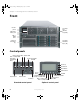
8510702.book Page 2 Thursday, July 7, 2005 11:21 AM Chapter 1: Checking Out Your Gateway Server Front Control panel Hot swap fans (behind faceplate) USB ports Video port CD or DVD drive 5.
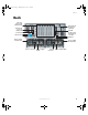
510702.book Page 3 Thursday, July 7, 2005 11:21 AM Back Back PCI slots (shown with EMI shields) Fiber channel module slot (optional) ID LED Gb network ports (2) USB ports RJ-45 Server management connector Serial port Monitor port ID button Power supply module latch Power supply module latch Power connector Power supply LEDs Power connector www.gateway.
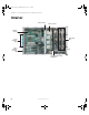
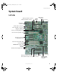
8510702.book Page 4 Thursday, July 7, 2005 11:21 AM Chapter 1: Checking Out Your Gateway Server Interior Center brace CPU Sockets System board Hot-swap fans Card retention clips Fiber module retention clip Front Hot-swap drive bay backplane 4 www.gateway.
8510702.
8510702.book Page 6 Thursday, July 7, 2005 11:21 AM Chapter 1: Checking Out Your Gateway Server Right side Front panel connector Power distribution board signal connect DC power connectors CPU 1 socket CPU 2 socket CPU 4 socket CPU 3 socket VRM 9.1 connector (processor cache) Chassis intrusion connector SCSI channel A connector SCSI channel B connector VRM 10.2L connector VRM 10.2LD connector RAID smart battery connector 6 www.gateway.
8510702.book Page 7 Thursday, July 7, 2005 11:21 AM Getting Help Getting Help In addition to your operating system’s documentation, you can use the following information resources to help you use your server. System Companion CD Use the System Companion CD to access file utilities, Windows 2003 Server drivers, and documentation for your server and its components. For more information, see Using Your System Companion CD.
8510702.book Page 8 Thursday, July 7, 2005 11:21 AM Chapter 1: Checking Out Your Gateway Server 8 www.gateway.
8510702.
8510702.book Page 10 Thursday, July 7, 2005 11:21 AM Chapter 2: Setting Up Your Server Setting up the hardware To make sure that your working environment is safe: ■ Use a clean, dry, flat, stable surface for your server. Allow at least 6 inches at the back of the server for cabling and air circulation. ■ Use the instructions on your server’s setup poster to set up your hardware. ■ Use an uninterruptible power supply (UPS) with surge protection for protection from power outages and power spikes.
8510702.book Page 11 Thursday, July 7, 2005 11:21 AM Setting up the hardware Converting to pedestal configuration To convert your server to a pedestal configuration, you need a pedestal conversion kit. To order the conversion kit, contact Gateway Customer Care, Gateway Sales, or visit accessories.gateway.com. For more information on contacting Customer Care, see “Telephone support” on page 223.
8510702.book Page 12 Thursday, July 7, 2005 11:21 AM Chapter 2: Setting Up Your Server 5 Turn the server over so the bottom is facing up, then position the outer cover, supplied with the conversion kit, on the bottom of the chassis. Screw Outer cover 6 12 Align the screw holes in the outer cover with the holes in the chassis and secure with the six screws provided with the kit. www.gateway.
8510702.book Page 13 Thursday, July 7, 2005 11:21 AM Setting up the hardware 7 Align each of the casters with its screw hole on the (new) bottom of the server and secure with one Phillips screw per caster (provided with caster assembly). Caster Screw 8 Remove the Torx screws securing the rack faceplate to the front of the chassis, then remove the faceplate.
8510702.book Page 14 Thursday, July 7, 2005 11:21 AM Chapter 2: Setting Up Your Server 14 10 Reinstall the optional control panel by following the instructions in “Removing and installing the control panel” on page 84. 11 Set the server upright on its casters and reconnect the data and power cables. www.gateway.
8510702.book Page 15 Thursday, July 7, 2005 11:21 AM Protecting from power source problems Protecting from power source problems Surge protectors, line conditioners, and uninterruptible power supplies can help protect your server against power source problems. Surge protectors During a power surge, the voltage level of electricity coming into your server can increase to far above normal levels and cause data loss or server damage.
8510702.book Page 16 Thursday, July 7, 2005 11:21 AM Chapter 2: Setting Up Your Server Starting your server Before you start your server for the first time: When you plug the AC power cords into the power supplies, wait for 20 to 30 seconds. The system will automatically power on for about 3 seconds, then power down. This allows the BMC to initialize the out-of-band management capabilities.
8510702.book Page 17 Thursday, July 7, 2005 11:21 AM Starting your server When the power/sleep LED is... It means... Green The server is turned on. Off The server is turned off (if ACPI is off). Slowly blinking Low power state — S1 (if ACPI is on). Off Low power state — S4/S5 (if ACPI is on). Important During the POST sequence, it takes from 3 to 10 minutes to see the first screen. This is normal and does not indicate an error or problem.
8510702.book Page 18 Thursday, July 7, 2005 11:21 AM Chapter 2: Setting Up Your Server ■ Boot Maintenance Manager - A menu of choices that lets you configure boot options and boot environment variables. ■ BIOS Setup Utility - Lets you configure the server BIOS settings. ■ POST Error Manager - Lets you view POST errors detected by the system.
8510702.book Page 19 Thursday, July 7, 2005 11:21 AM Starting your server 3 Press the up and down arrow keys to select the device you want to boot from, then press ENTER. Common choices include: ■ Removable Dev. (Removable device) ■ ATAPI CDROM (CD or DVD drive) ■ Hard Drive ■ IBA GE NIC (Network boot) Understanding the power-on self-test When you turn on your server, the power-on self-test (POST) routine checks the server memory and components.
8510702.book Page 20 Thursday, July 7, 2005 11:21 AM Chapter 2: Setting Up Your Server Controlling your server Local control Your server can be controlled locally by installing a USB keyboard and a USB mouse. There are USB connectors, as well as video connectors, on both the front and back of the server. There are no PS/2 connectors on this server. Remote control The BIOS supports redirection of both video and keyboard through a serial link (COM port) on this server.
8510702.book Page 21 Thursday, July 7, 2005 11:21 AM Controlling your server Keystroke mappings During console redirection, the remote terminal (which may be a dumb terminal or a system with a modem running a communication program) sends keystrokes to the local server. The local server passes video back over this same link. The keystroke mappings follow VT-UTF8 format with the following extensions. Setting up alias keys The DEL and CTRL + (function key) combinations are synonyms for the F2 or Setup key.
8510702.book Page 22 Thursday, July 7, 2005 11:21 AM Chapter 2: Setting Up Your Server Limitations The BIOS console redirection terminates after an EFI-aware operating system calls EFI Boot Service ExitBootServices. The operating system is responsible for continuing the console redirection after that point. BIOS console redirection is a text console and any graphical data, such as a logo, is not redirected.
8510702.book Page 23 Thursday, July 7, 2005 11:21 AM Controlling your server To configure the console: 1 2 3 Turn on the console system and let the operating system start. 4 When the Connect To window opens, click the COM port of the console to which the null modem cable is connected (for example, COM1). 5 When the COM1 Properties window opens, make the following settings: 6 7 Click Start, All Programs, Accessories, Communications, then click Hyperterminal.
8510702.book Page 24 Thursday, July 7, 2005 11:21 AM Chapter 2: Setting Up Your Server Turning off your server Every time you turn off your server, first shut down the operating system. You may lose data if you do not follow the correct procedure. To turn off the server: 1 See the operating system’s documentation or online help for instructions on shutting down the operating system. Whenever possible, you should use the operating system’s shut down procedure instead of pressing the power button.
8510702.book Page 25 Thursday, July 7, 2005 11:21 AM Setting up the operating system Setting up the operating system If you ordered your server with the operating system already installed by Gateway, in most cases it is completely installed and the basic settings are already configured. The Windows Small Business Server operating system may require additional installation, depending on the version you ordered.
8510702.book Page 26 Thursday, July 7, 2005 11:21 AM Chapter 2: Setting Up Your Server Initial hardware settings Your server comes from the manufacturer with the correct initial hardware settings to operate your server as configured. However, at some point you might want to change settings to reflect a tasking change, a change in security requirements, or the addition of new resources to your server.
8510702.book Page 27 Thursday, July 7, 2005 11:21 AM Configuring SCSI features Configuring SCSI features The LSI Logic MPT SCSI Setup Utility lets you configure your server’s SCSI features. For information on configuring your RAID solutions, see “Configuring your RAID solutions” on page 163. To access the LSI Logic MPT SCSI Setup Utility: 1 Press CTRL + C during POST, right after the memory test but prior to entering the System Options menu. The LSI Logic MPT SCSI Setup Utility main menu screen opens.
8510702.book Page 28 Thursday, July 7, 2005 11:21 AM Chapter 2: Setting Up Your Server 2 Press F2 to access the menu bar at the top of the screen, then press the HOME and END keys to select the Boot Adapter List. The Boot Adapter List screen opens. This list lets you add or remove boot adapters by highlighting the boot adapter and pressing the + or - key to change the status. 3 If you do not want to make any changes, press ESC to exit the utility.
8510702.book Page 29 Thursday, July 7, 2005 11:21 AM Configuring SCSI features 4 Use the up and down arrow keys to select one of the following options: ■ Cancel Exit - To cancel the exit and return to the adapter or device properties screen. ■ Save Changes then exit this menu - To save your changes and exit the menu. ■ Discard changes then exit this menu - To discard your changes and exit the menu. ■ Exit the Configuration Utility - To exit the utility entirely.
8510702.book Page 30 Thursday, July 7, 2005 11:21 AM Chapter 2: Setting Up Your Server 4 ■ Disable Integrated RAID (No or Yes) ■ Support Interrupt (Hook Interrupt (default) or Bypass Interrupt Hook) ■ (to restore the default configuration of the adapters) Press ESC to discard your changes and exit. - OR When you are finished making changes, press ENTER, The Exit menu screen will open.
8510702.book Page 31 Thursday, July 7, 2005 11:21 AM Configuring SCSI features To access and change the Adapter Properties List: 1 2 Follow the instructions in “To access the LSI Logic MPT SCSI Setup Utility:” on page 27. Use the up and down arrow keys to highlight the adapter to be configured, then press ENTER. The following message will be displayed: Scanning for devices...
8510702.book Page 32 Thursday, July 7, 2005 11:21 AM Chapter 2: Setting Up Your Server 4 ■ Secondary Cluster Server (No or Yes) ■ Termination Control (Auto) ■ (to discard the changes and restore the default configuration of the adapters) If you selected anything but , go to Step 6. - OR If you selected , press ENTER. The Device Properties screen opens.
8510702.book Page 33 Thursday, July 7, 2005 11:21 AM Configuring SCSI features 6 ■ Disconnect (On or Off) ■ SCSI Timeout (<10>) ■ Queue Tags (On or Off) ■ (to discard the changes and restore the default configuration) Press ESC to discard your changes and exit. - OR When you are finished making changes, press ENTER, The Exit menu screen will open.
8510702.book Page 34 Thursday, July 7, 2005 11:21 AM Chapter 2: Setting Up Your Server 34 www.gateway.
8510702.
8510702.book Page 36 Thursday, July 7, 2005 11:21 AM Chapter 3: Managing and Maintaining Your Server System administration Gateway Server Manager Gateway Server Manager lets you manage multiple computers on a Windows network from a single window, then implement commands and policies across the network with a single action. With Gateway Server Manager, you can run system management tasks which are triggered by certain events or conditions. Printed documentation comes with the Gateway Server Manager CD.
8510702.
8510702.
8510702.book Page 39 Thursday, July 7, 2005 11:21 AM System administration Menu Options Description Control the server Boot flags (select from available boot flags) Configure boot order ■ ■ Set the flag — one time reboot Reboot the system Power control ■ ■ Power control Power on Power off (graceful or hard) Reset Power control IPMI control IPMI control ■ ■ Power on Power off (graceful or hard) ■ Send the chipset a power control command.
8510702.book Page 40 Thursday, July 7, 2005 11:21 AM Chapter 3: Managing and Maintaining Your Server You can: ■ Enter either password to finish starting the server. ■ Enter the supervisor password to access the BIOS Setup utility. For information about resetting BIOS passwords, see “Resetting BIOS passwords” on page 161. To set the BIOS security passwords: 1 Restart your server, then press any key when the Gateway logo screen appears during startup. The System Options menu opens.
8510702.book Page 41 Thursday, July 7, 2005 11:21 AM Identifying your server Identifying your server While you are working on a cabinet that contains several slim servers, it can be difficult to keep track of which server or servers you are currently working on. The System ID indicator is a blue LED that you can turn on to help you locate the correct server. For the System ID indicator to turn on, the server does not need to be turned on, but it does need to be plugged in.
8510702.book Page 42 Thursday, July 7, 2005 11:21 AM Chapter 3: Managing and Maintaining Your Server Creating a DOS-bootable System Update Package (SUP) CD Several utilities available on this server require that you boot the server to DOS. A DOS-bootable SUP CD, containing the update files, provides a convenient way to accomplish this.
8510702.book Page 43 Thursday, July 7, 2005 11:21 AM Creating a DOS-bootable System Update Package (SUP) CD Booting from the SUP CD: 1 Restart your server, then press any key when the Gateway logo screen appears during startup. The System Options menu opens. 2 Select BIOS Setup utility, then press ENTER. The BIOS Setup utility opens. 3 Use the down arrow key to select Boot Manager, then press ENTER. The Boot Option menu opens. www.gateway.
8510702.book Page 44 Thursday, July 7, 2005 11:21 AM Chapter 3: Managing and Maintaining Your Server 4 Select the CD drive on the Boot Options menu, then press ENTER. The server will now boot to the CD drive. If the CD drive is not detected, see “CD or DVD drive” on page 214. 5 6 7 Insert the bootable CD into the CD drive. 8 9 Select BIOS Setup utility, then press ENTER. The BIOS Setup utility opens. 10 44 Exit the System Options menu and let the server continue to boot.
8510702.book Page 45 Thursday, July 7, 2005 11:21 AM Baseboard Management Controller (BMC) Baseboard Management Controller (BMC) The Baseboard Management Controller (BMC) monitors system platform management events and logs their occurrences in the non-volatile System Event Log (SEL). This includes events such as over temperature and over-voltage conditions, and fan failures.
8510702.
8510702.book Page 47 Thursday, July 7, 2005 11:21 AM Baseboard Management Controller (BMC) ■ PCI SMBus is accessible to the management controller. This allows PCI add-in cards that support manageability to log events to the System Event Log (SEL).
8510702.book Page 48 Thursday, July 7, 2005 11:21 AM Chapter 3: Managing and Maintaining Your Server To update the BMC firmware without Boot Block and Force Firmware updates: 1 Download the current SUP CD image from www.support.gateway.com and create a DOS-bootable SUP CD. For information on creating a SUP CD, see “Creating a DOS-bootable System Update Package (SUP) CD” on page 42. 2 3 Follow the instructions included in the ReadMe.txt file in the BMC folder.
8510702.book Page 49 Thursday, July 7, 2005 11:21 AM Baseboard Management Controller (BMC) 4 Move the shorting block from pins 2-3 to pins 1-2 on the Boot Block Update jumper (J1B1) on the IMM module. 1 2 3 1 2 3 J1B1 2 - 3 Default - Boot block protected 1 - 2 Boot block unprotected 5 Follow the instructions in “Closing the server case” on page 72, then reconnect the power cord. 6 Download the current SUP CD image from www.support.gateway.com and create a DOS-bootable SUP CD.
8510702.book Page 50 Thursday, July 7, 2005 11:21 AM Chapter 3: Managing and Maintaining Your Server 12 Move the shorting block from pins 1-2 to pins 2-3 on the Boot Block Update jumper (J1B1) on the IMM module. 13 14 Follow the instructions in “Closing the server case” on page 72. 15 16 Select BIOS Setup utility, then press ENTER. The BIOS Setup utility opens. 17 Restart your server, then press any key when the Gateway logo screen appears during startup. The System Options menu opens.
8510702.book Page 51 Thursday, July 7, 2005 11:21 AM Baseboard Management Controller (BMC) 3 Under Management, IPMI Configuration, click LAN and Serial Configuration, then LAN access, Use Custom LAN configuration to the BMC, Customize LAN options, LAN port 03, Edit. 4 Under IP Settings, enter the IP address, subnet mask, and other settings, then click Apply.
8510702.book Page 52 Thursday, July 7, 2005 11:21 AM Chapter 3: Managing and Maintaining Your Server 3 The web server displays the System Summary page after the user is authenticated. Using the Embedded Web Server scripting interface The Embedded Web Server can be accessed from a scripting language such as Perl or JavaScript. The client script sends a GET or POST request to the server. The server will return either an HTML web page or an XML response.
8510702.
8510702.book Page 54 Thursday, July 7, 2005 11:21 AM Chapter 3: Managing and Maintaining Your Server HTML Example In this example, the client-side page loads the page returned by the Embedded Web Server into a frame:
8510702.book Page 55 Thursday, July 7, 2005 11:21 AM Baseboard Management Controller (BMC) ■ Update the non-volatile storage device associated with the BMC that holds the SDR and FRU information ■ Generically handle FRU devices that might not be associated with the BMC ■ View and direct results to the standard output device Each time you update the FRU/SDR, we recommend that you check support.gateway.com for the most current version of the utility.
8510702.book Page 56 Thursday, July 7, 2005 11:21 AM Chapter 3: Managing and Maintaining Your Server 3 Open the DIAG folder and click SELVIEW.EXE. The SEL Viewer screen opens. 4 The following menu items are available: File - includes options for opening and saving system event log records, including: Open - lets you open an existing SEL data file for viewing. Save As - lets you save the SEL data to a file. Exit - lets you exit the SEL Viewer utility.
8510702.
8510702.book Page 58 Thursday, July 7, 2005 11:21 AM Chapter 3: Managing and Maintaining Your Server Using your System Companion CD You can use your System Companion CD to: ■ Install hardware drivers ■ Install programs ■ Access various utilities ■ View server documentation Instructions for using the CD are provided in Using Your System Companion CD, a booklet which is provided with the CD. 58 www.gateway.
8510702.book Page 59 Thursday, July 7, 2005 11:21 AM Preparing for system recovery Preparing for system recovery If your system files are corrupted, you may not be able to start the server from the hard drive. Startup diskettes are diskettes that let you start the server and attempt to fix the problem. See your operating system’s documentation or online help for instructions on creating startup diskettes.
8510702.book Page 60 Thursday, July 7, 2005 11:21 AM Chapter 3: Managing and Maintaining Your Server Caring for your server To extend the life of your server: ■ Be careful not to bump or drop your server. ■ When transporting your server, we recommend that you put it in the original packaging materials. ■ Keep your server and magnetic media away from equipment that generates magnetic fields. ■ Avoid subjecting your server to extreme temperatures.
8510702.book Page 61 Thursday, July 7, 2005 11:21 AM Caring for your server Cleaning tips ■ Always turn off your server and other peripheral devices before cleaning any components. Warning When you shut down your server, the power turns off, but some electrical current still flows through your server. To avoid possible injury from electrical shock, unplug the power cords and all other cables connected to the server.
8510702.book Page 62 Thursday, July 7, 2005 11:21 AM Chapter 3: Managing and Maintaining Your Server 62 www.gateway.
8510702.book Page 63 Thursday, July 7, 2005 11:21 AM Chapter 4 Installing Components • Opening and closing the server case • Installing and replacing major components You must open your server case to install components. If you are not comfortable with these procedures, get help from a more experienced computer user or computer service technician, or contact Gateway Customer Care.
8510702.
8510702.book Page 65 Thursday, July 7, 2005 11:21 AM Preventing static electricity discharge Preventing static electricity discharge The components inside your server are extremely sensitive to static electricity, also known as electrostatic discharge (ESD). Warning To avoid exposure to dangerous electrical voltages and moving parts, turn off your server and unplug the power cords and modem cable before opening the server case.
8510702.book Page 66 Thursday, July 7, 2005 11:21 AM Chapter 4: Installing Components Opening the server case Because the components inside your server are extremely sensitive to static electricity, make sure that you follow the instructions at the beginning of this chapter to avoid static electricity damage. Warning Caution The total power requirement for this server exceeds the 240 VA energy hazard limits that define an operator accessible area.
8510702.book Page 67 Thursday, July 7, 2005 11:21 AM Removing and installing the processor air baffle 3 Using a Phillips screwdriver, loosen the two captive screws on the faceplate securing the top cover to the server case. 4 When the screws are loose, slide the top cover toward the back of the case about ½ inch. 5 Lift the top cover away from the server and place it out of the way.
8510702.book Page 68 Thursday, July 7, 2005 11:21 AM Chapter 4: Installing Components ■ Change jumper settings ■ Remove or install the front panel I/O board To remove the processor air baffle: 1 2 3 Follow the instructions in “Preventing static electricity discharge” on page 65. Follow the instructions in “Opening the server case” on page 66. Lift the processor air baffle from the chassis. Processor air baffle 68 www.gateway.
8510702.book Page 69 Thursday, July 7, 2005 11:21 AM Removing and installing the center brace To install the processor air baffle: 1 2 Follow the instructions in “Preventing static electricity discharge” on page 65. Place the processor air baffle in the chassis.
8510702.book Page 70 Thursday, July 7, 2005 11:21 AM Chapter 4: Installing Components To remove the center brace: 1 2 3 Follow the instructions in “Preventing static electricity discharge” on page 65. 4 Move the two center brace locks (located on both sides of and behind the center brace) toward the back of the case to unlock the center brace. Follow the instructions in “Opening the server case” on page 66.
8510702.book Page 71 Thursday, July 7, 2005 11:21 AM Removing and installing the center brace To install the center brace: 1 Align the center brace with the guides on both sides of the case and with the full-length PCI expansion cards to the back, then lower the center brace into the case until it is fully seated. Center brace 2 Move the two center brace locks (located on both sides of and behind the center brace) toward the front of the case to lock the center brace into place.
8510702.book Page 72 Thursday, July 7, 2005 11:21 AM Chapter 4: Installing Components Closing the server case To close the server case: 72 1 Make sure that all of the internal cables are arranged inside the case so they will not be pinched when you close the case. 2 Align the tabs on the top cover with the slots in the chassis, then slide the top cover toward the front of the chassis until it meets the face plate.
8510702.book Page 73 Thursday, July 7, 2005 11:21 AM Installing drives Installing drives Your server’s basic configuration includes one CD (standard) or DVD (optional) drive. Your server also has two additional 5.25-inch drive bays, which can accommodate two half-height or one full height SCSI tape drive. Your server can have as many as ten, hot-swap SCSI drives in hot-swap drive bays. CD or DVD drive Hot-swap hard drive bays (10) 5.
8510702.book Page 74 Thursday, July 7, 2005 11:21 AM Chapter 4: Installing Components 2 3 Follow the instructions in “Opening the server case” on page 66. 4 Disconnect the SATA and power cables from the SATA-to-IDE converter board on the back of the CD or DVD drive. Remove the processor air baffle by following the instructions in “Removing and installing the processor air baffle” on page 67.
8510702.book Page 75 Thursday, July 7, 2005 11:21 AM Installing drives 7 Lift up on the right-rear corner of the CD or DVD drive to disengage it from the drive carrier, then remove it from the carrier. 8 Disconnect the SATA-to-IDE converter board from the back of the drive, then place the drive in an anti-static bag for storage. 9 Slide the empty drive carrier back into the server. - OR If you are replacing the drive, see “To install a CD or DVD drive:” on page 75, and begin at Step 6.
8510702.book Page 76 Thursday, July 7, 2005 11:21 AM Chapter 4: Installing Components 76 5 Remove the CD/DVD drive carrier from the server by following the instructions in “To remove the CD or DVD drive:” on page 73. 6 Remove the new drive from its packaging and place it, component-side down, on an ESD-protected work surface. 7 8 Record the model and serial numbers as necessary. 9 Place the left side of the drive into the drive carrier, then press down on the right side until it is firmly seated.
8510702.book Page 77 Thursday, July 7, 2005 11:21 AM Installing drives 12 Reconnect the front panel cable to the SCSI hot-swap backplane by following the instructions in “Replacing the SCSI hot-swap backplane” on page 139. 13 Replace the processor air baffle by following the instructions in “Removing and installing the processor air baffle” on page 67. 14 Follow the instructions in “Closing the server case” on page 72. Installing a fixed, removable-media drive in a 5.
8510702.book Page 78 Thursday, July 7, 2005 11:21 AM Chapter 4: Installing Components If you are adding a new drive to an available 5.25-inch device bay, remove the filler panel assembly from the bay by pressing and holding the two locking clips inward, then pulling the filler panel assembly out of the bay. 4 Remove the drive rails from the filler panel assembly by removing the screws holding the rails to the assembly, then go to Step 8.
8510702.book Page 79 Thursday, July 7, 2005 11:21 AM Installing drives 11 Slide the new drive into the drive bay until the drive rails snap into place. 12 Follow the instructions in “Closing the server case” on page 72. www.gateway.
10702.book Page 80 Thursday, July 7, 2005 11:21 AM Chapter 4: Installing Components Installing a hot-swap hard drive Use this procedure to add or replace hard drives in a hot-swap drive bay. Your server has room for as many as ten hot-swap drive carriers and each drive carrier holds a 1-inch high, Ultra320 SCSI, SCA-type hard drive, running at 15,000 RPM or slower. The SCSI backplane (and hot-swap drive bays) support only LVD (Low Voltage Differential) drives.
8510702.book Page 81 Thursday, July 7, 2005 11:21 AM Installing drives 2 If you are replacing a failed drive, determine which drive has failed by checking the drive status LEDs on the front of the drive carriers. Drive latch Drive status LED Caution Before you remove a failed drive, use the appropriate software and utilities installed on the server to stop all activity on the failed drive. Instructions for using the software are provided by the software manufacturer.
8510702.book Page 82 Thursday, July 7, 2005 11:21 AM Chapter 4: Installing Components - OR If you are adding a new drive, first remove the four screws securing the plastic retention device into the drive carrier, then remove the plastic retention device from the drive carrier. 5 82 Line up the screw holes in the new drive with the holes in the side of the drive carrier, then secure the drive to the carrier with the four screws you removed in Step 4. www.gateway.
8510702.book Page 83 Thursday, July 7, 2005 11:21 AM Installing drives 6 Make sure that the drive carrier’s release lever is open, then use the lever to slide the new drive into the empty hot-swap bay until it docks in the chassis. 7 Close the drive’s release lever by rotating the lever to the left to latch the drive carrier into position. www.gateway.
8510702.book Page 84 Thursday, July 7, 2005 11:21 AM Chapter 4: Installing Components Removing and installing the control panel Removal and installation of the control panel and front panel board is the same, regardless of whether your server is equipped with the standard control panel or the optional local control panel (LCP). To remove and install the control panel: 84 1 2 3 Follow the instructions in “Preventing static electricity discharge” on page 65.
8510702.book Page 85 Thursday, July 7, 2005 11:21 AM Memory Memory Your server has four PCI ×16 connectors on the system board for memory boards. Each memory board has sockets for four DIMMs and supports two DDR2 channels (with two DIMMs per channel). Memory boards support both single-rank and double-rank, registered DIMMs. One to four memory boards can be installed. Installing and removing memory boards Memory boards can be configured in either redundant or non-redundant configurations.
8510702.book Page 86 Thursday, July 7, 2005 11:21 AM Chapter 4: Installing Components ■ Cold memory add/replacement - If your server is not in a RAID or Mirrored configuration, memory boards can only be added or replaced when the system is turned off. For additional information, see “Cold removal and installation of memory boards” on page 89.
8510702.book Page 87 Thursday, July 7, 2005 11:21 AM Memory Hot removal and insertion of memory boards To replace a memory board or add memory while the system is on: 1 2 Follow the instructions in “Preventing static electricity discharge” on page 65. 3 Press the power button on the memory board you intend to replace. The orange Hot Plug Attention LED begins to flash. 4 When the orange Hot Plug Attention LED turns off, make sure the Power LED for the memory board is also off.
8510702.book Page 88 Thursday, July 7, 2005 11:21 AM Chapter 4: Installing Components Important 6 7 Pull up on the memory board handle and lift the memory board from the server. 8 Make sure the handle on the memory board is in the open/up position, then align the ends of memory board with the card guides at each end and insert the memory board into the memory board slot.
8510702.book Page 89 Thursday, July 7, 2005 11:21 AM Memory Cold removal and installation of memory boards To remove/replace a memory board while the system is off: 1 2 3 Follow the instructions in “Preventing static electricity discharge” on page 65. 4 Pull up on the memory board handle and lift the memory board from the server. 5 Install or replace DIMMs on the memory board by following the instructions in “Installing and removing DIMMs” on page 91.
8510702.book Page 90 Thursday, July 7, 2005 11:21 AM Chapter 4: Installing Components 7 8 Push the memory board handle down into the locked position. Follow the instructions in “Closing the server case” on page 72. To add a memory board while the system is off: 90 1 2 3 4 Follow the instructions in “Preventing static electricity discharge” on page 65.
8510702.book Page 91 Thursday, July 7, 2005 11:21 AM Memory Installing and removing DIMMs When you change the amount of memory in this server, memory must be added to, or removed from memory boards (see “Installing and removing memory boards” on page 85). When you upgrade your server memory, make sure that you install the correct type of memory. Your server supports from 512 MB to 64 GB total memory. Supported DIMM sizes include 256 MB, 512 MB, 1 GB, 2 GB and 4 GB.
8510702.book Page 92 Thursday, July 7, 2005 11:21 AM Chapter 4: Installing Components Caution Attempts to force non-DDR2 DIMMs into a socket on the memory board will result in damage to the DIMM, damage to the socket, or damage to both. Use extreme care when installing DIMMs. Applying too much pressure can damage the DIMM socket or the DIMM. DIMMs are keyed and can only be installed one way. Hold DIMMs by the edges. Do not touch the gold connectors or the components.
8510702.book Page 93 Thursday, July 7, 2005 11:21 AM Memory 4 Remove the DIMM cover from the memory board. a b c d 5 Pull out the DIMM cover latch. Press the DIMM cover tabs. Press the DIMM cover retainer tab. Lift the DIMM cover off the memory board. Pull the plastic tabs away from the sides of the memory sockets you intend to use. If you are removing or replacing a DIMM, remove the DIMM and place it in an anti-static bag.
8510702.book Page 94 Thursday, July 7, 2005 11:21 AM Chapter 4: Installing Components 6 Align the notch on the new module with the key in the memory module socket and press the module firmly into the socket. The tabs on the sides of the memory socket should secure the memory module automatically. 7 Reinstall the DIMM cover. a b c 94 Align the DIMM cover tabs with the top of the memory board. Press in the DIMM cover retainer tab. Press down on the DIMM cover until it clicks into place.
8510702.book Page 95 Thursday, July 7, 2005 11:21 AM Memory 10 Restart your server and open the BIOS Setup utility. Verify the System Memory listed in the Main menu. When you exit the BIOS Setup utility, make sure that the operating system loads completely. 11 Follow the instructions in “FRU/SDR Load utility” on page 54. Configuring memory options Memory sparing The chipset on the system board in the server supports memory sparing, which can provide a way to prevent data loss in case of DIMM failure.
8510702.book Page 96 Thursday, July 7, 2005 11:21 AM Chapter 4: Installing Components 7 Return to the Memory configuration menu and set the Sparing Threshold between 1 and 15. 8 Select View and Configure Memory Board x (where x is the memory board that is being configured). ■ 9 10 11 Make sure that the Board Status is Healthy. Set the Reserve Rank for Spare to Enabled. Press F10 to save your changes and exit. Press Y to confirm and the server reboots with the changes.
8510702.book Page 97 Thursday, July 7, 2005 11:21 AM Memory 7 8 Press F10 to save your changes and exit. Press Y to confirm and the server reboots with the changes. Memory mirroring If the server contains two or four memory boards with equal memory capacity, the system can be configured for memory mirroring. Using memory mirroring, the memory on one memory board in the server is mirrored by a second memory board.
8510702.book Page 98 Thursday, July 7, 2005 11:21 AM Chapter 4: Installing Components PCI expansion cards Your server uses the PCI-X bus. Use the following chart to determine the PCI slot into which you should install your expansion card. Caution Only PCI cards in slots 1 - 5 are hot-swappable. Do not attempt to install or remove PCI cards in slots 6 or 7 without turning off your server and disconnecting it from the AC power source.
8510702.book Page 99 Thursday, July 7, 2005 11:21 AM PCI expansion cards Hot installation or removal of PCI expansion cards Adjacent to each of the five hot-swap PCI slots are power LEDs and attention LEDs. The attention LEDs indicate the operational condition of the slot, and the power LEDs indicate the power condition of the slot. There is also an Attention button, located by the green arrow on the PCI divider label, which is used to initiate the sequence to hot-swap a card.
8510702.book Page 100 Thursday, July 7, 2005 11:21 AM Chapter 4: Installing Components 4 5 Highlight the device (card) to be removed, then click Stop. 6 Push the top of the card retention clip down slightly, then rotate it out the back of the case to open it. Wait for the PCI power LED adjacent to the selected PCI slot to turn off, then disconnect any cables that are attached to the card. Card retention clip 7 8 For full-length cards, press the front PCI card retainer to release the card.
8510702.book Page 101 Thursday, July 7, 2005 11:21 AM PCI expansion cards 10 11 Install an expansion slot cover over the empty slot, or install a replacement card in the slot. ■ To install an expansion slot cover, align the cover with the slot from the back of the chassis, then press the cover into the slot. Rotate the card retention clip into the chassis to the closed position. ■ To install a replacement card, see “To install a hot-swap PCI expansion card:” on page 102.
8510702.book Page 102 Thursday, July 7, 2005 11:21 AM Chapter 4: Installing Components 9 10 Install an expansion slot cover over the empty slot, or install a replacement card in the slot. ■ To install an expansion slot cover, align the cover with the slot from the back of the chassis, then press the cover into the slot. Rotate the card retention clip into the chassis to the closed position. ■ To install a replacement card, see “To install a hot-swap PCI expansion card:” on page 102.
8510702.book Page 103 Thursday, July 7, 2005 11:21 AM PCI expansion cards 6 Push the top of the card retention clip for the slot you are using down slightly, then rotate it out the back of the case to open it. 7 If necessary, remove the expansion slot cover for the slot you are using by sliding it up from inside the chassis. 8 Align the card with the slot, then press down to seat the card in the slot. If you are installing a full-length card, slide the front of the card into the front PCI card guide.
8510702.book Page 104 Thursday, July 7, 2005 11:21 AM Chapter 4: Installing Components If you are using the hardware hot-plug interface, press the attention button for the slot containing the new PCI card. Important 12 Wait for the power LED to turn on. Important 13 To abort the hot-plug operation, press the attention button again within five seconds. If the attention LED is blinking, a power fault has occurred.
8510702.book Page 105 Thursday, July 7, 2005 11:21 AM PCI expansion cards 7 Align the card with the slot, then press down to seat the card in the slot. If you are installing a full-length card, slide the front of the card into the front PCI card guide. You can slightly rock the card end-to-end to seat it, but do not bend the card sideways. 8 9 Rotate the card retention clip into the chassis to the closed position. Connect any required cabling to the card.
8510702.book Page 106 Thursday, July 7, 2005 11:21 AM Chapter 4: Installing Components Fibre channel module The fibre channel module (optional) is an intelligent, high-performance adapter with a Qlogic ISP2322 FC controller, designed for high-end server systems like this one. It combines a RISC processor with two 2 Gbps transceivers, a 64-bit, 133 MHz PCI-X interface, and a Fibre Channel Protocol Manager (FPM).
8510702.book Page 107 Thursday, July 7, 2005 11:21 AM Fibre channel module Activity Green LED Orange LED Red LED 2 Gbps link established Two flashes every 4 seconds Off Off 2 Gbps activity Two flashes every 4 seconds On Off Firmware error Varies Varies On Beacon* Constant flash Constant flash Constant flash * Beacon is used by the Qlogic SANSurfer FE HBA Manager software to identify a specific adapter in the system.
8510702.book Page 108 Thursday, July 7, 2005 11:21 AM Chapter 4: Installing Components Fibre channel HBA manager software The QLogic SANsurfer FC HBA Manager is a device management software suite for the installation, configuration, and management of QLogic-based HBAs. The software includes asset management, remote configuration, monitoring, physical identification (beacon), and loading of drivers onto multiple devices at one time.
8510702.book Page 109 Thursday, July 7, 2005 11:21 AM Fibre channel module 5 Push the top of the fibre channel module retention clip down slightly, then rotate it to the open position out the back of the case. 6 If you are removing the fibre channel module: a b c Pull up on the module to remove it from the slot on the system board. Place it in a static-free bag for storage.
8510702.book Page 110 Thursday, July 7, 2005 11:21 AM Chapter 4: Installing Components 7 110 If you are installing the fibre channel module: a If necessary, remove the expansion slot cover by pulling it up from inside the chassis. b Remove the fibre channel module from its anti-static bag, being careful not to touch the gold edge connectors at the bottom of the module. c d e Place the module on a clean, ESD-protected work surface.
8510702.book Page 111 Thursday, July 7, 2005 11:21 AM Processors Processors The server requires a minimum of one Intel® Xeon™ MP processor or one Intel Xeon MP processor with iL3 cache. The processors must be installed in sequential order, from CPU socket 1 through CPU socket 4. Each processor socket must have either a processor and heat sink, or a thermal blank installed The server automatically detects the processors each time you turn on the server.
8510702.book Page 112 Thursday, July 7, 2005 11:21 AM Chapter 4: Installing Components Important You must have a processor in the CPU_1 socket, or your server will not start. If you are upgrading your server from one processor to two (or more), you may need to reconfigure your operating system so it can recognize the additional processor. For more information, see your operating system’s documentation. To remove a processor: 112 1 Install the most current BIOS version.
8510702.book Page 113 Thursday, July 7, 2005 11:21 AM Processors 7 Remove the heat sink by lifting it from the processor. Caution The heat sink has Thermal Interface Material (TIM) on the bottom. Be careful not to damage this material when you remove the heat sink from the processor. If removing the heat sink also pulls the processor out of the processor socket, the processor could be damaged. Check the pins on the processor to make sure they are not bent or damaged.
8510702.book Page 114 Thursday, July 7, 2005 11:21 AM Chapter 4: Installing Components Caution A heat sink must be installed on the processor. Installing a processor without a heat sink could damage the processor. Thermal blanks must be present in all processor sockets where no processor is installed. If a processor is removed, a thermal blank must be installed in the empty socket.
8510702.book Page 115 Thursday, July 7, 2005 11:21 AM Processors 6 If a processor thermal blank is installed, remove it by loosening the four screws (one at each corner) and lifting the thermal blank from the processor socket. 7 Make sure that the processor release lever is in the open position. www.gateway.
8510702.book Page 116 Thursday, July 7, 2005 11:21 AM Chapter 4: Installing Components 8 Install the new processor into the processor socket. Make sure that: ■ You install the processors in order, from CPU socket 1 through CPU socket 4, with the new processor being installed in the next available socket ■ The triangular arrow on the corner of the processor aligns with the triangular hole on the corner of the processor socket ■ The processor is flush with the socket.
8510702.book Page 117 Thursday, July 7, 2005 11:21 AM Processors 10 Place the heat sink on the processor, making sure the thermal grease is applied correctly or the Thermal Interface Material (TIM) is aligned between the heat sink and the processor. Caution Failure to apply the Thermal Interface Material or thermal grease between the processor and the heat sink could result in damage to the processor and the server.
8510702.book Page 118 Thursday, July 7, 2005 11:21 AM Chapter 4: Installing Components Processor VRM requirements This server requires the installation of two different types of VRMs (Voltage Regulator Modules). The number and types of VRMs required depends on the number of processors installed. Before installing or removing processors, refer to the following guidelines: Number of processors installed VRMs required 1 No VRM required 2 No VRM required 3 One 9.
8510702.book Page 119 Thursday, July 7, 2005 11:21 AM Processors 5 Holding the VRM by the edges, align the notch on the bottom edge of the VRM with the notch in the VRM socket and press the VRM firmly into the socket. 6 7 Make sure the tabs on the sides of the VRM socket close securely. 8 Follow the instructions in “Closing the server case” on page 72. Replace the processor air baffle by following the instructions in “Removing and installing the processor air baffle” on page 67.
8510702.book Page 120 Thursday, July 7, 2005 11:21 AM Chapter 4: Installing Components 5 Holding the VRM by the edges, lift it from the socket. 6 7 Place the VRM into an anti-static bag for storage. 8 Follow the instructions in “Closing the server case” on page 72. Replace the processor air baffle by following the instructions in “Removing and installing the processor air baffle” on page 67.
8510702.book Page 121 Thursday, July 7, 2005 11:21 AM Processors 4 Remove the memory boards or memory board air baffles from memory slots C and D by following the instructions in “Installing and removing memory boards” on page 85. 5 Remove the fibre channel module by following the instructions in “Installing or removing the fibre channel module” on page 108.
8510702.book Page 122 Thursday, July 7, 2005 11:21 AM Chapter 4: Installing Components 10 11 If you are installing the VRM for the fourth processor, reinstall the VRM air baffle. 12 Replace the memory boards or memory board air baffles into memory slots C and D by following the instructions in “Installing and removing memory boards” on page 85. 13 Replace the processor air baffle by following the instructions in “Removing and installing the processor air baffle” on page 67.
8510702.book Page 123 Thursday, July 7, 2005 11:21 AM Processors 6 If you are removing the VRM for the fourth processor, remove the VRM air baffle by pushing down on the top of the baffle and pulling the baffle away at an angle from the center brace. 7 Gently spread the retaining clips at each end of the VRM socket which makes the VRM pop up from the socket. 8 9 10 11 Holding the VRM by the edges, remove it from the socket.
8510702.book Page 124 Thursday, July 7, 2005 11:21 AM Chapter 4: Installing Components Installing an Intel Management Module (IMM) To install an Intel Management Module (IMM): 1 2 3 4 Uninstall the Gateway Server Manager (GSM) software from your server. 5 Remove the memory boards or memory board air baffles from slots A and B, by following the instructions in “Installing and removing memory boards” on page 85.
8510702.book Page 125 Thursday, July 7, 2005 11:21 AM Installing an Intel Management Module (IMM) 7 Find the IMM connector on the right side of the system board. 8 Grasp the module board by one edge and the plastic handling strap (close to the mounting connector), align the board with the IMM connector on the system board, then gently apply pressure to seat the module. Make sure the module is fully seated and the nylon standoffs are inserted into the corresponding holes in the system board.
8510702.book Page 126 Thursday, July 7, 2005 11:21 AM Chapter 4: Installing Components Installing and removing the ROMB (RAID on Motherboard) activation key and dedicated RAID memory Functionality for RAID levels 5, 10, and 50 is enabled by using the optional Intel RAID Activation Key (1-wire serial security EEPROM) and dedicated RAID memory installed in the onboard RAID cache memory socket.
8510702.book Page 127 Thursday, July 7, 2005 11:21 AM Installing and removing the ROMB (RAID on Motherboard) activation key and dedicated 5 Remove the PCI expansion card from PCI slot 7 (if installed) by following the instructions in “Cold installation or removal of PCI expansion cards” on page 104. 6 7 Remove the RAID activation key and RAID DIMM from their anti-static packages. Insert the activation key into its socket on the system board (see “System board” on page 5 for the location of the socket.
8510702.book Page 128 Thursday, July 7, 2005 11:21 AM Chapter 4: Installing Components 9 Holding the DIMM by the edges, align the notch on the bottom edge of the DIMM with the notch in the DIMM socket and press the DIMM firmly into the socket. The tabs on the sides of the DIMM socket should secure the DIMM automatically. 10 Reinstall the PCI expansion card into PCI slot 7 (if removed) by following the instructions in “Cold installation or removal of PCI expansion cards” on page 104.
8510702.book Page 129 Thursday, July 7, 2005 11:21 AM Installing and removing the ROMB (RAID on Motherboard) activation key and dedicated 5 Gently spread the retaining clips at each end of the RAID DIMM socket causing the DIMM to lift from the socket. 6 7 8 Holding the DIMM by the edges, lift it from the socket. 9 Reinstall the memory board or memory board air baffle for slot C by following the instructions in “Installing and removing memory boards” on page 85.
8510702.book Page 130 Thursday, July 7, 2005 11:21 AM Chapter 4: Installing Components 130 5 Open the battery case, then connect the cable inside the battery case. 6 After closing the battery case, route the battery cable through the holder on the side of the chassis. 7 Attach the cable to the BBU connector (J1H1 - 2×10) on the system board. See “System board” on page 5 for the location of the connector. www.gateway.
8510702.book Page 131 Thursday, July 7, 2005 11:21 AM Installing and removing the ROMB (RAID on Motherboard) activation key and dedicated 8 Engage the retention tabs on the back of the battery with the matching slots in the side of the chassis, then push the battery to the left to latch it into place. 9 Reinstall the memory board or memory board air baffle into slot D by following the instructions in “Installing and removing memory boards” on page 85.
8510702.book Page 132 Thursday, July 7, 2005 11:21 AM Chapter 4: Installing Components 132 6 Push the battery to the right to disengage it from the side of the chassis, then remove it from the chassis. 7 Reinstall the memory board or memory board air baffle into slot D by following the instructions in “Installing and removing memory boards” on page 85.
8510702.book Page 133 Thursday, July 7, 2005 11:21 AM Power subsystem Power subsystem The power subsystem includes the power supply modules, the power distribution board, and the plug-in VRMs.
8510702.book Page 134 Thursday, July 7, 2005 11:21 AM Chapter 4: Installing Components LED Location Description Power good LED (green) Top This LED is lit whenever the power is turned on Fault LED (orange) Center This LED is lit when a power rail has failed, even if the power supply is in a latched state. The only time this LED is not lit during a fault condition is if the 3.3VSB is lost. This LED is not lit when the server is turned off.
8510702.book Page 135 Thursday, July 7, 2005 11:21 AM Power subsystem To replace a power supply module or active fan blank: 1 Examine the LED indicators on the back of each power supply modules to identify the failed module. The power supply module has failed if the center Fault LED (orange) indicator is on. If your server has two power supply modules, go to Step 3. 2 3 4 Turn off the server. 5 6 Place the power supply module (or active fan blank) on a clean, ESD-protected surface.
8510702.book Page 136 Thursday, July 7, 2005 11:21 AM Chapter 4: Installing Components 8 9 10 Plug the power cord into the AC connector on the power supply module. If your server only has a single power supply module, turn on the server. The new power supply module is ready if the green Power Good LED (top) and green AC OK LED are both on. Replacing a power distribution board Your server uses a power distribution board to enable the hot-swap capability and distribute power to the system.
8510702.book Page 137 Thursday, July 7, 2005 11:21 AM Power subsystem 8 Remove the seven (7) screws securing the power distribution board to the chassis, then lift the board from the chassis and place it in an anti-static bag for storage. 9 Remove the new power distribution board from its package and align it with the seven screw holes on the chassis. www.gateway.
8510702.book Page 138 Thursday, July 7, 2005 11:21 AM Chapter 4: Installing Components 138 10 Secure the new power distribution board to the chassis with the seven screws you previously removed. 11 Connect all power cables that you previously removed from the power distribution board. 12 Reinstall the SCSI backplane by following the instructions in “Replacing the SCSI hot-swap backplane” on page 139.
8510702.book Page 139 Thursday, July 7, 2005 11:21 AM Replacing the SCSI hot-swap backplane Replacing the SCSI hot-swap backplane Your server can hold as many as ten SCSI hot-swap drives in a hot-swap drive cage. The hot-swap drive cage is connected to the SCSI backplane, which provides power and data interface between the drives and the server. The SCSI hot-swap backplane is located behind the SCSI drive bays.
8510702.book Page 140 Thursday, July 7, 2005 11:21 AM Chapter 4: Installing Components 140 10 Pull out the blue, spring-loaded plunger (located at the top of the SCSI hot-swap backplane) that secures the backplane to the chassis, then pull the board up slightly to disengage the ten retention tabs holding the board to the chassis. 11 Tilt the SCSI hot-swap backplane back slightly, then lift it from the server and place it in an anti-static bag for storage. www.gateway.
8510702.book Page 141 Thursday, July 7, 2005 11:21 AM Replacing the SCSI hot-swap backplane 12 Remove the new SCSI hot-swap backplane from its package, then place it in the chassis by engaging the bottom three slots in the board with the three lower retention tabs in the chassis. 13 Move the top of the board forward, engaging the rest of the slots with the other retention tabs on the chassis, until all ten tabs are through the ten slots in the board.
8510702.book Page 142 Thursday, July 7, 2005 11:21 AM Chapter 4: Installing Components 142 20 Reinstall the processor air baffle by following the instructions in “Removing and installing the processor air baffle” on page 67 21 22 Follow the instructions in “Closing the server case” on page 72. Reinstall all of the drives into the hot-swap drive bays. Make sure that you replace the drives in the correct order by referring to your notes from Step 4. www.gateway.
8510702.book Page 143 Thursday, July 7, 2005 11:21 AM Replacing the front panel I/O board Replacing the front panel I/O board To replace the front panel I/O board: 1 2 3 Follow the instructions in “Preventing static electricity discharge” on page 65. 4 Disconnect the front panel I/O board and control panel cables from the front panel board. 5 Loosen the blue, captive thumbscrew in the center of the front panel I/O board, then slide the board back until the mounting tabs disengage from the board.
8510702.book Page 144 Thursday, July 7, 2005 11:21 AM Chapter 4: Installing Components 7 Remove the new front panel I/O board from its package and place it in the chassis, engaging the mounting tabs on the chassis with the slots in the new board. 8 Slide the front panel I/O board forward until it is seated on the mounting tabs, then tighten the blue, captive thumbscrew to secure the board. See “Torque settings” on page 64 for correct tightening specifications.
8510702.book Page 145 Thursday, July 7, 2005 11:21 AM Replacing a hot-swap fan Replacing a hot-swap fan If you are adding redundant hot-swap fans to your server, you must update the FRU/SDR. For more information, see “FRU/SDR Load utility” on page 54. Important Make sure that you replace a fan with an identical replacement fan. To replace a hot-swap fan: 1 2 3 Follow the instructions in “Preventing static electricity discharge” on page 65.
8510702.book Page 146 Thursday, July 7, 2005 11:21 AM Chapter 4: Installing Components 146 4 Squeeze the fan latches together to release the fan, then lift the fan from the chassis. 5 Orient the new fan in the same direction as the old fan (and existing fans), then insert the new fan into the fan slot until it snaps into place. 6 Wait for the new fan to spin up, then follow the instructions in “Closing the server case” on page 72. www.gateway.
8510702.book Page 147 Thursday, July 7, 2005 11:21 AM Replacing the CMOS battery Replacing the CMOS battery If the server clock does not keep time or the settings in the BIOS Setup utility are not saved when you turn off the server, replace the CMOS battery with an equivalent battery. Warning There is a danger of explosion if battery is incorrectly replaced. Replace only with the same or equivalent type of battery recommended by the manufacturer.
8510702.book Page 148 Thursday, July 7, 2005 11:21 AM Chapter 4: Installing Components 148 9 Push the battery toward the larger prongs until the edge of the battery clears the small prongs, then pull up on the battery and lift it from the server. 10 Make sure that the positive (+) side of the new battery is facing correctly, then press the new battery into the socket until it snaps into place.
8510702.book Page 149 Thursday, July 7, 2005 11:21 AM Replacing the system board Replacing the system board To replace the system board: 1 2 3 Follow the instructions in “Preventing static electricity discharge” on page 65. 4 Remove the processor thermal blanks, heat sinks, and processors by following the instructions in “Installation and removal of processors” on page 111.
8510702.book Page 150 Thursday, July 7, 2005 11:21 AM Chapter 4: Installing Components 150 13 Lift the blue, spring-loaded plunger in the center of the system board, then slide the board toward the front of the chassis until it is disengaged. 14 15 Lift the system board from the chassis and place it in an anti-static bag for storage. Set the new system board into the chassis with the processor sockets toward the front and the I/O connectors toward the back. www.gateway.
8510702.book Page 151 Thursday, July 7, 2005 11:21 AM Replacing the system board 16 Pull up the blue, spring-loaded plunger in the center of the board and slide the board toward the back of the chassis until the I/O connectors engage the back panel, then release the plunger. 17 Connect the three-cable bundle from the power distribution board to the power connectors on the system board (see “System board” on page 5). 18 19 20 21 Connect the chassis intrusion switch cable to the system board.
8510702.book Page 152 Thursday, July 7, 2005 11:21 AM Chapter 4: Installing Components 152 22 Reinstall all PCI expansion cards by following the instructions in “Cold installation or removal of PCI expansion cards” on page 104. 23 Reinstall the memory boards and memory board air baffles by following the instructions in “Installing and removing memory boards” on page 85.
8510702.
8510702.book Page 154 Thursday, July 7, 2005 11:21 AM Chapter 5: Using the BIOS Setup Utility Opening the BIOS Setup utility The BIOS Setup utility stores basic settings for your server. These settings include basic hardware configuration, resource settings, and password security. These settings are stored and saved even when the power is off. Caution The options in the BIOS Setup utility have been set at the factory for optimal performance.
8510702.book Page 155 Thursday, July 7, 2005 11:21 AM Updating the BIOS Updating the BIOS If you need a new version of the BIOS, you can download the BIOS update from Gateway, then install the new version from a diskette. To update the BIOS: 1 2 3 4 Print the appendix for BIOS Settings in this guide. 5 6 7 8 Select BIOS Setup Utility from the System Options menu, then press ENTER. 9 Follow the instructions in “FRU/SDR Load utility” on page 54. Download the BIOS update from support.gateway.com.
8510702.book Page 156 Thursday, July 7, 2005 11:21 AM Chapter 5: Using the BIOS Setup Utility Caution Moving the jumper while the power is on can damage your server. Always turn off the server and unplug the power cords and all other cables before changing the jumper. 3 Remove the jumper across pins 1-2 of header J8C3 (see the illustration on page 157 for the location of the jumper), then place the jumper across pins 2-3. 4 5 Follow the instructions in “Closing the server case” on page 72.
8510702.book Page 157 Thursday, July 7, 2005 11:21 AM Updating the BIOS 2 Turn off the server, then disconnect the power cords and all other cables connected to the server. 3 Follow the instructions in “Opening the server case” on page 66. Caution 4 5 Remove the jumper across pins 1-2 of jumper J4A3 (the BIOS Recovery jumper), then place the jumper across pins 2-3. FRB3 Disable BMC Reset FWHID J8C1 J8C2 J8C3 Insert the DOS-bootable recovery media into a USB port.
8510702.book Page 158 Thursday, July 7, 2005 11:21 AM Chapter 5: Using the BIOS Setup Utility 7 8 9 10 11 Remove the DOS-bootable recovery media. Turn off the server, then disconnect the power cords and all other cables connected to the server. Place the jumper back onto pins 1-2. Follow the instructions in “Closing the server case” on page 72. Plug in the AC power cords and turn on the server, then verify that the recovery was successful.
8510702.book Page 159 Thursday, July 7, 2005 11:21 AM Updating the BIOS 3 4 5 Remove the jumper across pins 1-2 of jumper J4A3, then place the jumper across pins 2-3. BMC Reset FWHID J8C1 J8C2 J8C3 Follow the instructions in “Closing the server case” on page 72. Insert a DOS-bootable CD (SCCD or current SUP CD) into the CD drive or a DOS-bootable USB disk-on-key containing a valid BIOS image into a USB port.
8510702.book Page 160 Thursday, July 7, 2005 11:21 AM Chapter 5: Using the BIOS Setup Utility 11 12 Follow the instructions in “Closing the server case” on page 72. Plug in the AC power cords and turn on the server, then verify that the recovery was successful. To recover the default BIOS settings using front control panel buttons: 1 2 3 4 5 Turn off the server, but leave it connected to the AC power source. Make sure that the NVRAM Clear jumper (J4A4) is in the default position (Not Clear).
8510702.book Page 161 Thursday, July 7, 2005 11:21 AM Updating the BIOS Resetting BIOS passwords To reset BIOS password(s), you must either reset and clear all BIOS settings, or use the Password Clear jumper (J4A1). To clear BIOS settings, follow the instructions in “Resetting the BIOS” on page 158. To clear the BIOS passwords using the password clear jumper: 1 Turn off the server, then disconnect the power cords and all other cables connected to the server.
8510702.book Page 162 Thursday, July 7, 2005 11:21 AM Chapter 5: Using the BIOS Setup Utility 7 8 9 162 Follow the instructions in “Opening the server case” on page 66. Place the jumper back onto pins 1-2. Follow the instructions in “Closing the server case” on page 72. www.gateway.
8510702.
8510702.book Page 164 Thursday, July 7, 2005 11:21 AM Chapter 6: Configuring your RAID solutions Introduction RAID configuration can take place in one of several ways, depending on which RAID solution(s) you have available on your server. Servers with the optional ROMB RAID solution can be configured by using either the RAID BIOS Console (text-based) configuration utility or by using the RAID Web Console (a GUI-based console available with your browser).
8510702.book Page 165 Thursday, July 7, 2005 11:21 AM Configuring your ROMB RAID solution with the RAID BIOS Console configuration utility Configuring your ROMB RAID solution with the RAID BIOS Console configuration utility The Intel RAID BIOS Console configuration utilities provide full-featured, HTML-based configuration and management of optional ROMB RAID arrays. The BIOS Console resides in firmware and is independent of the operating system.
8510702.book Page 166 Thursday, July 7, 2005 11:21 AM Chapter 6: Configuring your RAID solutions Icon Description Click on this icon to scan for adapters connected to your system. Click on this icon to display the properties of the adapter, such as the firmware version, BIOS version, RAM size, and initiator ID. Click on the icon to access the Configuration Wizard so that you can configure the arrays and logical drives. Click on this icon to silence the sound on the alarm.
8510702.book Page 167 Thursday, July 7, 2005 11:21 AM Configuring your ROMB RAID solution with the RAID BIOS Console configuration utility Important 4 5 If there is a configuration mismatch between the disks and the NVRAM, the utility automatically displays the Select Configuration screen. Choose whether the configuration should be read from the RAID array or from NVRAM. Select the configuration type, then click Next.
8510702.book Page 168 Thursday, July 7, 2005 11:21 AM Chapter 6: Configuring your RAID solutions 168 6 Select Custom Configuration, then click Next. The Array Definition screen opens. 7 Hold down the CTRL key and click each drive you want included in the array. To undo the changes, click Reclaim. www.gateway.
8510702.book Page 169 Thursday, July 7, 2005 11:21 AM Configuring your ROMB RAID solution with the RAID BIOS Console configuration utility 8 9 10 When the drives are defined, click Accept Array, then click Next. The Logical Drive definition screen opens. Select the RAID Level from the list. Select the Stripe Size from the list. Specify the size of the segment written to each disk in a RAID configuration. You can set the stripe size to 4, 8, 16, 32, 64, or 128 Kbytes. The default is 64 Kbytes.
8510702.book Page 170 Thursday, July 7, 2005 11:21 AM Chapter 6: Configuring your RAID solutions 12 Select the Write Policy from the list to set the write and cache policies. The write policy parameter specifies the cache write policy. You can set the write policy to: ■ Write-back caching - the controller sends a data transfer completion signal to the host when the controller cache receives all the data in a transaction.
8510702.book Page 171 Thursday, July 7, 2005 11:21 AM Configuring your ROMB RAID solution with the RAID BIOS Console configuration utility RAID 10: To configure a RAID 10 array, create multiple RAID 1 drive arrays (minimum of two) and enable the span option, then select the size of the logical drive. It is possible to span as many as eight arrays in a logical drive.
8510702.book Page 172 Thursday, July 7, 2005 11:21 AM Chapter 6: Configuring your RAID solutions 17 Click Accept to save the configuration, then click Yes to initialize the logical drive. The Logical Drives screen opens. 18 Click Initialize to begin the initialization process. If fast initialization is selected as the default for the adapter properties, a preliminary initialization will complete within seconds and full initialization will run in the background after the operating system is booted.
8510702.book Page 173 Thursday, July 7, 2005 11:21 AM Configuring your ROMB RAID solution with the RAID BIOS Console configuration utility 19 Click the Home icon on the top menu bar to return to the main configuration screen. 20 Select an additional logical drive to configure or exit the BIOS Console Configuration Utility and reboot the server. www.gateway.
8510702.book Page 174 Thursday, July 7, 2005 11:21 AM Chapter 6: Configuring your RAID solutions Configuring your ROMB RAID solution with the RAID Web Console The Intel RAID Web Console provides full-featured, GUI-based configuration and management of optional ROMB RAID arrays. The RAID Web Console is accessed by using your Web browser and is installed as software, specific for your server’s operating system.
8510702.book Page 175 Thursday, July 7, 2005 11:21 AM Configuring your ROMB RAID solution with the RAID Web Console ■ RAID Registration Server is a module running on a RAID server that tracks RAID servers on a network. It contains a database of the RAID servers that have registered with it as RAID servers. RAID servers automatically register with the registration server once the registration server’s IP address is entered into their RAID server regsrv.dat file.
8510702.book Page 176 Thursday, July 7, 2005 11:21 AM Chapter 6: Configuring your RAID solutions Registration server The Registration server is a RAID server that also has a registration process running on it. The Registration server maintains a database of all RAID servers in a network, providing remote management of all available RAID servers through a single point of access. Only RAID servers can be designated as a registration server.
8510702.book Page 177 Thursday, July 7, 2005 11:21 AM Configuring your ROMB RAID solution with the RAID Web Console To enable the registration server: 1 2 Set a static IP address for the registration server. On each RAID server to be managed, edit the regserv.dat file located in the etc directory. Change the localhost entry to the host name of the registration server. The following edited file shows the localhost entry changed to intel, as an example. www.gateway.
8510702.book Page 178 Thursday, July 7, 2005 11:21 AM Chapter 6: Configuring your RAID solutions 3 Edit the hosts file on each RAID server to resolve the registration server IP address. Add the IP address and the host name of the registration server as shown in the following example. 4 178 Save the file. It will take about two minutes for the change to take effect. www.gateway.
8510702.book Page 179 Thursday, July 7, 2005 11:21 AM Configuring your ROMB RAID solution with the RAID Web Console Registration server operation When the networking option is enabled in Web Console, the RAID server will look up the registration server address in the regserv.dat file and resolve it to an IP address through the hosts file or through DNS resolution. The RAID server will then register its name and address with the registration server.
8510702.book Page 180 Thursday, July 7, 2005 11:21 AM Chapter 6: Configuring your RAID solutions Installing the Windows Web Console To install the Windows Web Console: 1 Insert the System Companion CD into the CD drive and double-click on the Install icon to run the program. 2 3 4 Click Next. The license agreement and README screens appear. Click Next to accept the license agreement and proceed.
8510702.book Page 181 Thursday, July 7, 2005 11:21 AM Configuring your ROMB RAID solution with the RAID Web Console 5 Select Standalone or Networking, then click Next. The Setup screen opens. Choosing Standalone lets the correct modules be installed to support local management through the Web Console. Select Networking if you want to remotely manage this or other remote systems. 6 Select features to install from the list. ■ RAID Web Server - This option provides the Java interface for the RAID Server.
8510702.book Page 182 Thursday, July 7, 2005 11:21 AM Chapter 6: Configuring your RAID solutions 10 Edit the REGSERV.DAT and HOSTS.DAT files. The installation retrieves the files for editing. The REGSERV.DAT file is located at: C:\winnt\system32\drivers\etc. The HOSTS.DAT file is located at: C:\winnt\system32\drivers\etc. 11 Save the file and exit, then reboot your system.
8510702.book Page 183 Thursday, July 7, 2005 11:21 AM Configuring your ROMB RAID solution with the RAID Web Console De-registering and re-registering under Web Console If the registration server fails or shuts down, the other RAID servers or RAID clients must log back into the registration server after the registration server is online. RAID servers can register into the registration servers without resetting.
8510702.book Page 184 Thursday, July 7, 2005 11:21 AM Chapter 6: Configuring your RAID solutions Launching the Web Console Web console is launched from a Web Browser that supports Java scripts. Microsoft Internet Explorer 5.5 or later and Netscape Browsers are supported. To launch the Web Console: 1 Launch your Web browser and access the RAID controller through port address 3570. The RAID Web Console initial screen opens. For Example, for a remote system: http://192.168.0.
8510702.book Page 185 Thursday, July 7, 2005 11:21 AM Launching the Web Console 2 Select the RAID controller to be managed by clicking the name of the server in the window (MCC-IN in this example). The Login screen opens. You will be presented with an option to control read only functions of the RAID controller or full access to the RAID controllers configuration options. You must have the correct rights to manage the RAID controller’s configuration options. www.gateway.
8510702.book Page 186 Thursday, July 7, 2005 11:21 AM Chapter 6: Configuring your RAID solutions 3 186 Select Full Access, enter you password, then click Submit. The Management Options screen opens. www.gateway.
8510702.book Page 187 Thursday, July 7, 2005 11:21 AM Launching the Web Console The following table describes the options available on this screen. Option Description Adapter This option lets you configure the adapter properties. Config Wizard This option provides a series of options to let you create new drive arrays, add capacity to existing arrays, or modify existing arrays. Channel Properties This option lets you configure the properties of the available SCSI channels on the RAID controller.
8510702.book Page 188 Thursday, July 7, 2005 11:21 AM Chapter 6: Configuring your RAID solutions Custom RAID configuration If you choose Custom Configuration, the Web Console displays the Array Definition screen with an Arrays pane containing all previously configured arrays. Each logical drive has a label (such as LD 0), RAID level, and drive capacity. Spanned arrays use hyphenated array numbers such as LD0-1, which indicates disk drive 1 in array 0.
8510702.book Page 189 Thursday, July 7, 2005 11:21 AM Launching the Web Console 4 Click Accept to save the logical drive. If space is still available in the current array, the new logical drive appears in the array and you can define additional logical drives in the current array. The Wizard continues to create logical drives for the same array until there is no more space available in the array, or until there are 40 logical drives in the array.
8510702.book Page 190 Thursday, July 7, 2005 11:21 AM Chapter 6: Configuring your RAID solutions To check the rebuild rate: ■ Select the correct adapter from the Adapter box, then select Rebuild Rate from the Adapter menu. If there is more than one adapter in the system, click each adapter and check the rebuild rate. The rebuild rate is not affected when you clear the configuration. To Exit the Web Console: ■ Select Exit from the Configuration menu to quit the Web Console.
8510702.book Page 191 Thursday, July 7, 2005 11:21 AM Launching the Web Console Removing a physical drive from an array To selectively remove hard drives from an existing array: 1 2 Go to the Config View screen. Highlight the logical drive you want to remove, then select Delete from the left pane. www.gateway.
8510702.book Page 192 Thursday, July 7, 2005 11:21 AM Chapter 6: Configuring your RAID solutions 192 www.gateway.
8510702.book Page 193 Thursday, July 7, 2005 11:21 AM Chapter 7 Troubleshooting • Interpreting error messages and codes • Troubleshooting • Getting telephone support and training If the suggestions in this chapter do not correct the problem, see “Telephone support” on page 223 for more information about how to get help.
8510702.book Page 194 Thursday, July 7, 2005 11:21 AM Chapter 7: Troubleshooting Safety guidelines While troubleshooting your server, follow these safety guidelines: ■ Do not attempt to open the monitor. To do so is extremely dangerous. Even if the power is disconnected, energy stored in the monitor components can be dangerous. Also, opening the monitor voids its warranty. ■ Make sure that you are grounded correctly before opening the server case.
8510702.book Page 195 Thursday, July 7, 2005 11:21 AM Error messages Error messages These messages often indicate procedural errors such as typing an incorrect keystroke or trying to save a file to a write-protected diskette. Some messages, however, may indicate a problem that requires further troubleshooting. These are general messages and do not represent all possible error messages you might receive.
8510702.book Page 196 Thursday, July 7, 2005 11:21 AM Chapter 7: Troubleshooting Invalid partition table ■ The master boot record may be corrupt. For troubleshooting information, see “The master boot record is corrupted” on page 219. Invalid password ■ Enter your password again. Some passwords are case sensitive. ■ If you do not know the password, you may need to reinstall the software you are trying to access. ■ System startup passwords are stored in BIOS.
8510702.book Page 197 Thursday, July 7, 2005 11:21 AM Troubleshooting Troubleshooting First steps Try these steps first before going to the following sections: ■ Make sure that the power cords are connected to your server and an AC outlet and that the AC outlet is supplying power. ■ If you use a UPS, make sure that it is turned on and is rated to handle the power required by your server.
8510702.book Page 198 Thursday, July 7, 2005 11:21 AM Chapter 7: Troubleshooting To restart and access the BIOS Setup utility: 1 2 3 ■ At the Gateway Logo screen, press any key to access the System Options menu. The System Options menu opens. Select the BIOS Setup Utility, then press ENTER. The BIOS Setup utility opens. Correct any discrepancies, then save changes and exit.
8510702.book Page 199 Thursday, July 7, 2005 11:21 AM Beep codes Beep codes Post error beep codes Whenever a recoverable error occurs during the power-on self-test (POST), the BIOS displays an error message that describes the problem. The BIOS also sounds a beep code (one long tone followed by two short tones) during POST if the video configuration fails (a faulty video controller) or if an expansion card is not functioning correctly. One short beep indicates the BIOS will boot the operating system.
8510702.book Page 200 Thursday, July 7, 2005 11:21 AM Chapter 7: Troubleshooting Beeps Error Message POST Progress Code Description 4 Recovery complete FFh BIOS recovery succeeded, ready for power-down and reboot. Additional beep codes provided by Intel Management Modules In addition to the beep codes above, the following additional beep codes are provided by the Intel Management Module: 200 Beep Codes Description 1 Control panel CMOS clear has been initiated 1-5-1-1 Processor failure.
8510702.book Page 201 Thursday, July 7, 2005 11:21 AM LED information LED information The various subsystems in this server include LEDs that can assist you in troubleshooting your system.
8510702.book Page 202 Thursday, July 7, 2005 11:21 AM Chapter 7: Troubleshooting LED Name Function Location Color Description Power supply status (3) Power supply module status On each power supply module Green and Orange Top LED (green) - On means power is good Middle LED (orange) - On means there is a fault condition in this power supply module Bottom LED (green) - On means that AC power to this power supply module is OK.
8510702.
8510702.
8510702.
8510702.
8510702.book Page 207 Thursday, July 7, 2005 11:21 AM LED information POST error messages and handling The following table lists the error codes, associated messages, the severity of the error and the system response.
8510702.
8510702.
8510702.
8510702.
8510702.
8510702.
8510702.
8510702.book Page 215 Thursday, July 7, 2005 11:21 AM LED information Your CD or DVD drive tray does not open ■ Press a straightened paper clip wire into the CD or DVD drive’s manual eject hole. The drive tray opens. ■ If this problem happens frequently while the server is turned on, the drive may be defective. Diskette drive The diskette drive is not recognized ■ Restart your server. ■ Unplug and replug the USB cable from the drive to the server.
8510702.book Page 216 Thursday, July 7, 2005 11:21 AM Chapter 7: Troubleshooting 6 Remove all other bootable media from the server. Your server has problems booting to the USB flash memory device that has a partition and is formatted correctly To correct the problem: 1 2 3 4 Run FDISK/MBR Make sure the partition is active. Make sure the partition has been correctly formatted as a bootable partition. Use the boot manager to select the boot device.
8510702.book Page 217 Thursday, July 7, 2005 11:21 AM LED information Your server has a SCSI hard drive and a USB flash memory device installed and the server continues to boot from the SCSI drive The SCSI hard drive is set as the first Legacy Hard Disk Drive in the Legacy Hard disk drive order. To change the boot order: Important Make sure to document the boot order before it is changed. Also make sure you have a backup of any data.
8510702.book Page 218 Thursday, July 7, 2005 11:21 AM Chapter 7: Troubleshooting ■ Make sure that you have installed the necessary software or driver. For more information, see the card’s documentation. ■ Reseat the card. For more information, see “PCI expansion cards” on page 98. ■ Install the card in a different slot.
8510702.book Page 219 Thursday, July 7, 2005 11:21 AM LED information ■ Make sure that the last device on the SCSI cable is correctly terminated. For more information about SCSI device configurations, see the device’s documentation. ■ Use a different SCSI cable. The master boot record is corrupted ■ In a Windows network operating system, repair the master boot record using FDISK. To repair the master boot record: ■ At a DOS command prompt, type fdisk/mbr, then press ENTER.
8510702.book Page 220 Thursday, July 7, 2005 11:21 AM Chapter 7: Troubleshooting Monitor Your server has no video and the LED on the control panel indicates that the system is in reset mode ■ Make sure that all the cables, processors, and VRMs are fully seated. ■ Possibly a faulty VRM. Replace the VRM(s). Your server is running but there is no picture ■ Adjust the brightness and contrast controls to the center position. ■ Make sure that the monitor is plugged in and turned on.
8510702.book Page 221 Thursday, July 7, 2005 11:21 AM LED information ■ If your server is plugged into a UPS, make sure that the UPS is connected securely to an electrical outlet, turned on, and working correctly. One way to check this is to plug the server directly into a wall outlet, bypassing the UPS. ■ Check the power supply modules on the back of the server. Make sure that the LEDs all indicate that the power supplies are working and the available AC power is good.
8510702.book Page 222 Thursday, July 7, 2005 11:21 AM Chapter 7: Troubleshooting 222 ■ You may need to reconfigure your operating system so it recognizes the additional processor. For more information, see your operating system’s documentation. ■ Check to make sure you added the additional VRMs required for processors 3 and 4 and that they are fully seated in their sockets. See “Processor VRM requirements” on page 118. www.gateway.
8510702.book Page 223 Thursday, July 7, 2005 11:21 AM Telephone support Telephone support Before calling Gateway Customer Care If you have a technical problem with your server, follow these recommendations before contacting Gateway Customer Care: ■ Make sure that your server is connected correctly to a grounded AC outlet that is supplying power. ■ If a peripheral device, such as a keyboard or mouse, does not appear to work, make sure that all cables are plugged in securely.
8510702.book Page 224 Thursday, July 7, 2005 11:21 AM Chapter 7: Troubleshooting Telephone support Gateway offers a wide range of customer service, technical support, and information services. Telephone numbers You can access the following services through your telephone to get answers to your questions: Resource Service description How to reach Gateway Customer Care Talk to a Gateway Customer Care representative about a non-tutorial technical support question.
8510702.book Page 225 Thursday, July 7, 2005 11:21 AM Appendix A Server Specifications The following specifications are for the standard configuration. Your server may contain optional equipment. All specifications are subject to change.
8510702.book Page 226 Thursday, July 7, 2005 11:21 AM Appendix A: Server Specifications System specifications Case size 10.5 × 27.8 × 17.6 inches (26.2 × 70.6 × 44.7 cm) Weight 130 lbs (60 kg) or more (varies by configuration) Fans 6 hot-swap system fans (speed adjustable) in a redundant (5+1) configuration Ports ■ ■ ■ ■ USB (5) Serial (1) VGA (2) RJ-45 LAN (2 + 1 SM NIC) Local Control Panel An LCD Local Control Panel is optional Drives (removable media) Two 5.
8510702.
8510702.book Page 228 Thursday, July 7, 2005 11:21 AM Appendix A: Server Specifications RAID Two Serial ATA 150 ports from the ICH5-R supporting entry level RAID functionality, including Integrated Mirroring and Integrated Striping (RAID levels 0 and 1). The LSI Logic 53C1030 supports the LSI logic Integrated Mirroring Enhanced (IME) and Integrated Striping (IS) technology (RAID levels 0 and 1).
8510702.
8510702.book Page 230 Thursday, July 7, 2005 11:21 AM Appendix A: Server Specifications Environmental specifications The following specifications identify maximum environmental conditions. At no time should the server run under conditions which violate these specifications. Variable Requirements Temperature Maximum rate of change: 18°F (10°C) per hour Nonoperating: -40° to 158°F (-40° to 70°C) Operating: 50° to 95°F (10° to 35°C); derated 0.9°F (0.5°C) for every 1,000 feet (305 meters) Max BTU/hr.
8510702.
8510702.book Page 232 Thursday, July 7, 2005 11:21 AM Appendix A: Server Specifications 232 Interrupt Description IRQ10 Generic, Option for SCI IRQ11 HPET #2, option for SCSI, TCO IRQ12 Mouse controller IRQ13 System interrupt/FERR IRQ14 Primary ATA, legacy mode PIRQA USB 1.1 controller 1 and 4 PIRQB Video PIRQC USB 1.1 controller 3, Native IDE, SATA PIRQD USB 1.
8510702.book Page 233 Thursday, July 7, 2005 11:21 AM Additional specifications Additional specifications For more information about your server, such as memory size, hard drive size, and processor type, visit Gateway’s Support page at support.gateway.com. The Support page also has links to additional Gateway documentation and detailed specifications for your own server. www.gateway.
8510702.book Page 234 Thursday, July 7, 2005 11:21 AM Appendix A: Server Specifications 234 www.gateway.
8510702.book Page 235 Thursday, July 7, 2005 11:21 AM Appendix B BIOS Settings You can print this appendix, then record your custom BIOS settings on the printout.
8510702.book Page 236 Thursday, July 7, 2005 11:21 AM Appendix B: To view all BIOS settings: 1 2 3 Restart your server. Open the System Options menu by pressing any key while your server restarts. When the System Options menu opens, select the BIOS Setup utility, then press ENTER. The BIOS Setup utility opens. Select menus and submenus to display setting information.
8510702.
8510702.
8510702.book Page 239 Thursday, July 7, 2005 11:21 AM BIOS menu BIOS submenu Setting Value Enable On-board Video Enabled Video Disabled Hard Disk Write Protect Disabled Enabled USB USB Controller Enable Enabled Disabled USB 2.
8510702.book Page 240 Thursday, July 7, 2005 11:21 AM Appendix B: BIOS menu BIOS submenu Setting Value Enable Slot 7 ROM Enabled Disabled Enable FC Card ROM Enabled Disabled Server Management Console Redirection COM1 Console Redirection Link to COM1 Console Redirection sub-menu on page 243.
8510702.book Page 241 Thursday, July 7, 2005 11:21 AM BIOS menu BIOS submenu Setting Value NIC1 MAC Address SEL Logging Clear Log Enabled Disabled FRB Information Processor #(n) Information Link to Processor #n Information sub-menu on page 236.
8510702.book Page 242 Thursday, July 7, 2005 11:21 AM Appendix B: BIOS menu BIOS submenu Setting Value Discard Changes and Exit Save Changes Discard Changes Restore Defaults Save User Default Values Restore User Default Values Caution Before changing modes, back up array data and delete existing arrays, if any. Otherwise, loss of data may occur. After operating system installation with a selected SCSI RAID mode, only change this mode selection if you are prepared to rebuild the RAID array.
8510702.book Page 243 Thursday, July 7, 2005 11:21 AM BIOS submenu BIOS 2nd level submenu Setting Value Hot Add (possible) Yes/No Board Interleave BIOS submenu BIOS 2nd level submenu Setting Value Console Redirection Sub-Menu COM1 Console Redirection Enable Slot 1 ROM Enabled Disabled Flow Control None RTS/CTS XON/XOFF CTS/RTS + CD Baud Rate 9600 19.2K 38.4K 57.6K 115.2K Terminal Type VT100 VT100+ VT-UTF8 PC-ANSI www.gateway.
8510702.book Page 244 Thursday, July 7, 2005 11:21 AM Appendix B: 244 www.gateway.
8510702.
8510702.book Page 246 Thursday, July 7, 2005 11:21 AM Appendix C: Field Replaceable Unit (FRU) Kits Available FRU kits FRU Kit Description DVD/CD-RW combo kit Slimline 8X DVD/24X CD-RW combo drive. For installation instructions, see “Installing and removing the CD or DVD drive” on page 73. Local control display (LCD) kit Local Control Display (LCD) panel. For installation instructions, see “Removing and installing the control panel” on page 84.
8510702.book Page 247 Thursday, July 7, 2005 11:21 AM Available FRU kits FRU Kit Description Certance DAT-72 5.25" TBU kit ■ The kit contains the following: Certance DAT-72 5.25" 36 GB/72 GB blank tape ■ TBU cleaning cartridge ■ MFG instruction: SCSI cable for TBU kits For instructions on installing 5.25-inch drives, see “Installing a fixed, removable-media drive in a 5.25-inch drive bay” on page 77. ■ Certance DAT-432 5.25" TBU kit The kit contains the following: Certance DAT-432 5.
8510702.book Page 248 Thursday, July 7, 2005 11:21 AM Appendix C: Field Replaceable Unit (FRU) Kits FRU Kit Description ROMB feature 256MB-RAM DDR2 kit ■ The kit contains the following: ROMB enable key 256MB-RAM DDR2 (ECC) For installation instructions, see “Installing and removing the ROMB (RAID on Motherboard) activation key and dedicated RAID memory” on page 126.
8510702.
8510702.book Page 250 Thursday, July 7, 2005 11:21 AM Appendix D: Introduction The EFI (Extensible Firmware Interface) Shell is an EFI application that lets other EFI applications be launched, EFI device drivers be loaded, and operating systems be booted. The EFI Shell provides an interface between operating systems and platform firmware. The combination of the EFI Shell and EFI firmware provides an environment that can be adapted to many hardware configurations.
8510702.book Page 251 Thursday, July 7, 2005 11:21 AM Basic EFI Shell commands Basic EFI Shell commands The following table shows a set of basic EFI Shell commands used to manage files, the EFI NVRAM Shell, and boot commands. Command Description : Changes drives. For example, entering fs0: and pressing ENTER changes the drive to the LS-240 drive.
8510702.
8510702.
8510702.book Page 254 Thursday, July 7, 2005 11:21 AM Appendix D: 254 www.gateway.
8510702.
8510702.book Page 256 Thursday, July 7, 2005 11:21 AM Appendix E: Safety, Regulatory, and Legal Information Important safety information Your Gateway system is designed and tested to meet the latest standards for safety of information technology equipment. However, to ensure safe use of this product, it is important that the safety instructions marked on the product and in the documentation are followed.
8510702.book Page 257 Thursday, July 7, 2005 11:21 AM Important Warning Do not use Gateway products in areas classified as hazardous locations. Such areas include patient care areas of medical and dental facilities, oxygen-laden environments, or industrial facilities. To reduce the risk of fire, use only No. 26 AWG or larger telecommunications line cord. www.gateway.
8510702.book Page 258 Thursday, July 7, 2005 11:21 AM Appendix E: Safety, Regulatory, and Legal Information Regulatory compliance statements United States of America Federal Communications Commission (FCC) Unintentional emitter per FCC Part 15 FCC Part 15 Class A Statement The server is designated as complying with Class A requirements if it bares the following text on the rating label: This device complies with Part 15 of the FCC Rules.
8510702.
8510702.book Page 260 Thursday, July 7, 2005 11:21 AM Appendix E: Safety, Regulatory, and Legal Information Users should make sure, for their own protection, that the electrical ground connections of the power utility, telephone lines, and internal metallic water pipe system, if present, are connected together. This precaution may be particularly important in rural areas. Warning To avoid electrical shock or equipment malfunction do not attempt to make electrical ground connections by yourself.
8510702.book Page 261 Thursday, July 7, 2005 11:21 AM Laser safety statement All Gateway systems equipped with CD and DVD drives comply with the appropriate safety standards, including IEC 825. The laser devices in these components are classified as “Class 1 Laser Products” under a US Department of Health and Human Services (DHHS) Radiation Performance Standard. Should the unit ever need servicing, contact an authorized service location.
8510702.book Page 262 Thursday, July 7, 2005 11:21 AM Appendix E: Safety, Regulatory, and Legal Information Environmental information The product you have purchased contains extracted natural resources that have been used in the manufacturing process. This product may contain substances known to be hazardous to the environment or to human health.
8510702.book Page 263 Thursday, July 7, 2005 11:21 AM Notices Copyright © 2005 Gateway, Inc. All Rights Reserved 7565 Irvine Center Drive Irvine, CA 92618-2930 USA All Rights Reserved This publication is protected by copyright and all rights are reserved. No part of it may be reproduced or transmitted by any means or in any form, without prior consent in writing from Gateway. The information in this manual has been carefully checked and is believed to be accurate. However, changes are made periodically.
8510702.book Page 264 Thursday, July 7, 2005 11:21 AM Appendix E: Safety, Regulatory, and Legal Information 264 www.gateway.
8510702.book Page 265 Thursday, July 7, 2005 11:21 AM Index board front panel 143 boot device 18 menu 18 booting from SUP CD 43 Numerics 5.
8510702.
8510702.
8510702.
8510702.
8510702.
8510702.
8510702.book Page 272 Thursday, July 7, 2005 11:21 AM 272 www.gateway.
MAN 9715 SRV USR GDE R0 06/05