Contents 1 Checking Out Your Gateway Server . . . . . . . . . . . . . . . . . . . . . . . . . . . . . 1 Front . . . . . . . . . . . . . . . . . . . . . . . . . . . . . . . . . . . . . . . . . . . . . . . . . . . . . . . . . . . . . Back . . . . . . . . . . . . . . . . . . . . . . . . . . . . . . . . . . . . . . . . . . . . . . . . . . . . . . . . . . . . . . Interior . . . . . . . . . . . . . . . . . . . . . . . . . . . . . . . . . . . . . . . . . . . . . . . . . . . . . . . . . . . . System board . . . . .
Installing an IDE drive . . . . . . . . . . . . . . . . . . . . . . . . . . . . . . . . . . . . . . . . . . . .35 Installing a SCSI hard drive . . . . . . . . . . . . . . . . . . . . . . . . . . . . . . . . . . . . . . . .42 Installing memory . . . . . . . . . . . . . . . . . . . . . . . . . . . . . . . . . . . . . . . . . . . . . . . . . . .45 Installing PCI expansion cards . . . . . . . . . . . . . . . . . . . . . . . . . . . . . . . . . . . . . . . . .47 Installing a processor . . . . . . . . . . . . . .
A Server Specifications . . . . . . . . . . . . . . . . . . . . . . . . . . . . . . . . . . . . . . . . . . . 99 System specifications . . . . . . . . . . . . . . . . . . . . . . . . . . . . . . . . . . . . . . . . . . . . . . System board specifications . . . . . . . . . . . . . . . . . . . . . . . . . . . . . . . . . . . . . . . . . Environmental specifications . . . . . . . . . . . . . . . . . . . . . . . . . . . . . . . . . . . . . . . . . Video specifications . . . . . . . . . . . . . . . . . . . . . .
iv
Checking Out Your Gateway Server 1 Read this chapter to learn: ■ Where drives, ports, jacks, and controls are located ■ Where system board components are located ■ What help resources are available 1
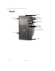
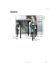
Chapter 1: Checking Out Your Gateway Server Front CD drive Diskette drive Cover release latch Cover release latch Additional drive bays Power button Reset button Power indicator Hard drive indicator Key lock USB ports 2 www.gateway.
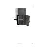
Front Hot-swap drives www.gateway.
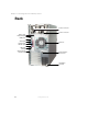
Chapter 1: Checking Out Your Gateway Server Back Power connector Power connector Mouse port Keyboard port USB ports Serial port Parallel port Monitor port Rear fan LAN jack (RJ-45) System board thumbscrew Card retention cover lever Kensington lock slot 4 www.gateway.
Interior Interior Cable clip Card retention cover release latch Rear fan Full-length card retention clip SCSI backplane Cable clip Hot-swap bay fan PCI card fan www.gateway.
Chapter 1: Checking Out Your Gateway Server System board Left side Processor 1 Processor 2 Rear fan connector 64-bit PCI card slots 32-bit PCI card slot 6 www.gateway.
System board Right side Power supply manageability connector Auxiliary power connector Processor 1 fan connector Front panel connector SCSI manageability connector Main power connector Voltage regulator slot 1 Memory module slots Voltage regulator slot 2 Diskette drive connector Primary IDE connector Secondary IDE connector Intrusion switch connector SCSI 2 connector SCSI 1 connector Processor 2 fan connector Hot-swap bay fan connector CMOS battery Configuration jumper JP7 PCI card fan connector www.
Chapter 1: Checking Out Your Gateway Server Getting Help In addition to your operating system’s documentation, you can use the following information resources to help you use your server. Server Companion CD Use the Server Companion CD to access file utilities, Windows 2000 Server drivers, and documentation for your server and its components. For more information, see Using Your Server Companion CD. Gateway Web site Gateway provides a variety of information on its Web site to help you use your server.
Setting Up Your Server 2 Read this chapter to learn how to: ■ Use your server safely ■ Start and turn off your server ■ Restart (reboot) your server ■ Set up the operating system 9
Chapter 2: Setting Up Your Server Setting up the hardware To make sure that your working environment is safe: ■ Use a clean, dry, flat, stable surface for your server. Allow at least 6 inches at the rear of the server for cabling and air circulation. ■ Use the instructions on your server’s setup poster to set up your hardware. ■ Use a grounded (three-prong) surge protector. A surge protector helps protect against AC power fluctuations.
Protecting from power source problems Protecting from power source problems Surge protectors, line conditioners, and uninterruptible power supplies can help protect your server against power source problems. Surge protectors During a power surge, the voltage level of electricity coming into your server can increase to far above normal levels and cause data loss or server damage.
Chapter 2: Setting Up Your Server Line conditioners A line conditioner protects your server from the small fluctuations in voltage from an electrical supply. Most servers can handle this variation, called line noise, without problems. However, some electrical sources include more line noise than normal. Line noise can also be a problem if your server is located near, or shares a circuit with, a device that causes electromagnetic interference, such as a television or a motor.
Starting your server Starting your server Before you start your server for the first time: ■ Make sure that the server and monitor are plugged into a power outlet or surge protector and that the surge protector (if you are using one) is turned on. ■ Make sure that all cables are connected securely to the correct ports and jacks on the back of the server. Warning When you connect peripheral devices to the server, make sure that your server and devices are turned off and the power cords are unplugged.
Chapter 2: Setting Up Your Server If nothing happens when you press the power button: 2 ■ Make sure that the power cords are plugged in securely and that your surge protector (if you are using one) is plugged in and turned on. ■ Make sure that the monitor is connected to the server, plugged into the power outlet or surge protector, and turned on. You may also need to adjust the monitor’s brightness and contrast controls.
Turning off your server Turning off your server Every time you turn off your server, first shut down the operating system. You may lose data if you do not follow the correct procedure. To turn off the server: 1 See the operating system’s documentation or online help for instructions on shutting down the operating system. Whenever possible, you should use the operating system’s shut down procedure instead of pressing the power button.
Chapter 2: Setting Up Your Server Setting up the operating system If you ordered your server with the operating system already installed by Gateway, it is completely installed and the basic settings are already configured. See your operating system’s documentation for instructions on configuring advanced settings for your specific network. If you are installing an operating system because it was not already installed by Gateway, see the appropriate installation guide for instructions. 16 www.gateway.
Maintaining Your Server 3 Read this chapter to learn how to: ■ Care for your server ■ Record the BIOS configuration ■ Manage your server and network 17
Chapter 3: Maintaining Your Server Caring for your server To extend the life of your server: ■ Be careful not to bump or drop your server. ■ When transporting your server, we recommend that you put it in the original packaging materials. ■ Keep your server and magnetic media away from equipment that generates magnetic fields. ■ Avoid subjecting your server to extreme temperatures. Do not expose your server to heating ducts or other heat-generating objects.
Caring for your server Cleaning tips ■ Always turn off your server and other peripheral devices before cleaning any components. Warning When you shut down your server, the power turns off, but some electrical current still flows through your server. To avoid possible injury from electrical shock, unplug the power cords and all other cables connected to the server. ■ Use a damp, lint-free cloth to clean your server and other parts of your server system.
Chapter 3: Maintaining Your Server Cleaning the tape drive If you use a tape drive to back up your files, regular maintenance will lengthen the life of the drive. To maintain the drive’s reliability: 20 ■ Clean the drive monthly with the cleaning cartridge included with the drive. ■ Remove the tape from the drive whenever the drive is not in use. www.gateway.
Preparing for system recovery Preparing for system recovery If your system files are corrupted, you may not be able to start the server from the hard drive. Startup diskettes are diskettes that let you start the server and attempt to fix the problem. See your operating system’s documentation or online help for instructions on creating startup diskettes. Some operating systems also let you create an emergency repair diskette to back up critical operating system files.
Chapter 3: Maintaining Your Server System administration Gateway Server Manager Gateway Server Manager lets you manage multiple computers on a Windows network from a single window, then implement commands and policies across the network with a single action. With Gateway Server Manager, you can run system management tasks which are triggered by certain events or conditions. Printed documentation comes with the Gateway Server Manager CD. You can find additional documentation in the program’s online help.
System administration 3 Select the password to set according to the following table. Option Description Supervisor password To control access to system configuration, set a supervisor password. Using a supervisor password lets you make changes to any setting in the BIOS. Passwords can be cleared. To clear the passwords, see “Resetting BIOS passwords” on page 79. User password The supervisor password must be set up before a user password can be set.
Chapter 3: Maintaining Your Server Using your Server Companion CD You can use your Server Companion CD to: ■ Install hardware drivers ■ Install programs ■ View server documentation Instructions for using the CD are provided in Using Your Server Companion CD. 24 www.gateway.
Installing Components 4 Read this chapter to learn how to: ■ Open and close the server case ■ Install drives ■ Install expansion cards and memory modules ■ Install processors and replace voltage regulators ■ Check and replace the power supplies ■ Replace the SCSI backplanes ■ Replace the system board ■ Replace case fans ■ Replace the CMOS battery You must open your server case to install components.
Chapter 4: Installing Components Preparing to install components Selecting a place to work Work on your server in an area that: ■ Is clean (avoid dusty areas) ■ Is a low-static environment (avoid carpeted areas) ■ Has a stable surface on which to set your server ■ Has enough room to place all of your server parts ■ Is near a grounded outlet so you can test your server after installation ■ Is near a telephone (in case you need help from Gateway Technical Support).
Preventing static electricity discharge Preventing static electricity discharge The components inside your server are extremely sensitive to static electricity, also known as electrostatic discharge (ESD). Warning ESD can permanently damage electrostatic discharge-sensitive components in the server. Prevent ESD damage by following ESD guidelines every time you open the server case.
Chapter 4: Installing Components Opening the server case Because the components inside your server are extremely sensitive to static electricity, make sure that you follow the instructions at the beginning of this chapter to avoid static electricity damage. Warning For correct cooling and air flow, always reinstall the side panel and the air duct (if included) before you turn on the server. Operating the server without the cover in place can damage server components.
Opening the server case 3 Unlock the front cover. Release latch Release latch Lock 4 Press the two front cover release latches, then pull the cover away from the server. 5 For more stability, place the server on its side. www.gateway.
Chapter 4: Installing Components 6 Loosen the three captive thumbscrews that secure the side panel to the server. Thumbscrews 7 30 Slide the side panel toward the front of the case about ½ inch, then lift the panel away from the server. www.gateway.
Opening the server case 8 If your server has an air duct, pull the tab on the right until it releases the duct from the server, then lift the duct away from the server. www.gateway.
Chapter 4: Installing Components Closing the server case To close the server case: 1 2 For more stability, place the server on its side. 3 4 Replace the air duct if one came with your server. 5 Tighten the three captive thumbscrews that secure the front of the cover to the server case. Make sure that all of the internal cables are arranged inside the case so they will not be pinched when you close the case.
Closing the server case 7 Align the notch in the bottom of the front cover with the rail on the front of the case, then swing the cover against the case. 8 9 Lock the front cover. Reconnect the power cords and all other cables. www.gateway.
Chapter 4: Installing Components Installing drives Your server’s basic configuration includes one CD drive and one 3.5-inch diskette drive. Your server also has two additional 5.25-inch drive bays. Your server can have up to eight SCSI hard drives in the hot-swap bay behind the front access door. CD drive Diskette drive 5.25-inch drive bay 5.25-inch drive bay Hot-swap bays As you prepare to install drives, remember: 34 ■ Do not use the top 5.
Installing drives ■ ■ If cable-select is available (drive assignments will be marked on the cable), the IDE cable assigns the master/slave positions to the drives it connects. You can override these assignments using the jumpers on the drives. ■ If cable-select is not available and only one drive is attached to an IDE controller cable, configure the drive as master if it is a CD drive. If two drives of any type are attached to the cable, configure one as master and one as slave.
Chapter 4: Installing Components 3 If you are replacing a drive, go to Step 7. - OR If you are adding a new drive, press and hold the two locking clips against the bay’s 3.5-inch drive adapter, then pull it out of the server. 4 36 Press the drive bay face plate release tabs inward, then pull the face plate away from the front cover. www.gateway.
Installing drives 5 If you are adding a 3.5-inch hard drive, use the screws that came with your IDE hard drive to secure the drive to the 3.5-inch drive adapter. IDE hard drive screws IDE hard drive screws - OR - www.gateway.
Chapter 4: Installing Components If you are replacing the 3.5-inch drive adapter with a new 5.25-inch drive, remove the two screws connecting each mounting rail to the adapter, remove the rails, then attach the rails to the sides of your new drive. Mounting rail screw Mounting rail screw Mounting rail screw Mounting rail screw Two screws for mounting the rail onto CD and diskette drives are stored on each rail.
Installing drives 8 If you are removing a drive from one of the top two bays, first remove the 3.5-inch diskette drive so you can reach the 5.25-inch drive’s release latch. 9 Press the old drive’s release latches against the drive, then pull the drive out of the bay. www.gateway.
Chapter 4: Installing Components 10 Remove the screws that secure the mounting rails to the old drive, then use the screws to attach the rails to the new drive. Screw Screw Screws for mounting the rails onto most tape drives are stored in the case near the full-length card retention clips. Tape drive screws 40 11 Set any jumpers on the new drive. See the drive’s documentation for further instructions. 12 Slide the new drive into the drive bay until the drive rails snap into place. www.gateway.
Installing drives 13 Connect the drive cables. For more information, see the drive’s documentation. 14 Follow the instructions in “Closing the server case” on page 32. www.gateway.
Chapter 4: Installing Components Installing a SCSI hard drive Use this procedure to add or replace hard drives in the hot-swap bay. Your server supports up to eight 1-inch high 3.5-inch SCA SCSI hard drives. You can purchase additional SCSI drives through your Gateway sales representative. Important The numbers on the left side of the hot-swap bay identify the SCSI ID of each drive. Install the topmost drives first. Gateway tests and verifies the operation and compatibility of the drives it sells.
Installing drives 2 If a drive has failed, determine which drive has failed by running storage console software. Match the software’s SCSI ID for the failed drive with the SCSI ID number to the left of the hot-swap bays. 3 Pull the drive tray’s lever away from the server, then pull the tray straight out of the server. Caution 4 Before you remove a failed drive, use the appropriate software and utilities installed on the server to stop all activity on the failed drive.
Chapter 4: Installing Components If you are adding a new drive, remove the bag taped to the inside of the drive tray, then remove the screws from the bag. 44 5 Line up the screw holes in the new drive with the holes in the side of the drive tray, then secure the drive to the tray with the four screws you removed in Step 4. 6 Make sure that the tray’s release lever is open, then slide the new drive into the empty hot-swap bay. 7 Close the drive’s release lever. www.gateway.
Installing memory Installing memory When you upgrade your server memory, make sure that you install the correct type of memory module for your server. Your server uses PC2100 DDR SDRAM registered ECC DIMM memory. The following illustration shows the location of the memory modules on the system board. Warning Modules must be installed in identical pairs. Use only PC2100 DDR SDRAM registered ECC DIMM memory modules. Install memory first into slots 1 and 2, then into slots 3 and 4.
Chapter 4: Installing Components To install or replace memory: 46 1 Follow the instructions in “Preventing static electricity discharge” on page 27. 2 3 Follow the instructions in “Opening the server case” on page 28. 4 Align the notch on the new module with the notch in the memory module slot and press the module firmly into the slot. The tabs on the sides of the memory slot should secure the memory module automatically. 5 6 Follow the instructions in “Closing the server case” on page 32.
Installing PCI expansion cards Installing PCI expansion cards Your server uses the PCI-X bus. Use the following chart to determine the PCI slot you should install your expansion card into. PCI slot Description 1 Always runs at 64-bit/66 MHz. Supports 32-bit and 64-bit cards, 3.3 V or universal. 2-3 Paired slots. When only one card is installed in a slot of this pair, the slot can run at 64-bit/133 MHz. When two 64-bit/100 MHz cards are installed in this pair, the slot can run at 64-bit/100 MHz.
Chapter 4: Installing Components To replace, add, or reseat a PCI expansion card: 1 Follow the instructions in “Preventing static electricity discharge” on page 27. 2 3 Follow the instructions in “Opening the server case” on page 28. 4 If you are removing a full-length card, pull back on the card retention clip that secures the end of the card. If you are replacing a card, disconnect any cables that are attached to the old card.
Installing PCI expansion cards 5 Pull the card retention cover’s release lever, then swing the retention cover away from the expansion cards. Release lever Card retention cover 6 If you are replacing a card, remove the old expansion card. You can slightly seesaw the card end-to-end to loosen the card, but do not bend the card sideways. Warning 7 Do not touch the contacts on the bottom part of the expansion card. Touching the contacts can cause electrostatic damage to the card.
Chapter 4: Installing Components 8 Push the card retention cover against the expansion cards until the retention cover clicks into place under the release lever. Release lever Card retention cover - OR Press on the card retention cover lever on the back of the server until the lever is flush with the back of the case. 9 50 If you are installing a full-length card, press down on the card retention clip to secure the end of the card. www.gateway.
Installing PCI expansion cards 10 Connect any cables to the card. For more information, see the instructions in the card’s documentation. 11 12 Follow the instructions in “Closing the server case” on page 32. See the card’s documentation for software installation instructions. www.gateway.
Chapter 4: Installing Components Installing a processor The server is compatible with Intel® Xeon processors with 512 KB cache. The server automatically detects the processors each time you turn on the server. Whenever you install new processors, you should first install the most current version of the BIOS. For more information, see “Updating the BIOS” on page 77. Important You must have a processor in the upper (processor 1) slot, or your server will not start.
Installing a processor 4 If your server has a passive heat sink, press down on the heat sink locking lever on each side, push them slightly away from the heat sink, then lift the levers out of the way. - OR If your server has a heat sink with a fan, press down on the heat sink locking lever on each side, push them slightly away from the heat sink, then lift the levers out of the way. Unplug the heat sink’s fan from its connector on the system board. www.gateway.
Chapter 4: Installing Components 5 Remove the heat sink. Important 6 Press down on the processor locking lever, push it slightly away from the processor, then rotate the lever a full 135° to release the processor. 7 8 Remove the old processor. Install the new processor into the processor socket.
Installing a processor 12 If your heat sink has a fan, plug the fan into the connector on the system board next to the heat sink. Processor 1 fan connector Processor 2 fan connector 13 If you have installed a new processor into the lower (processor 2) slot for the first time, you also need to install a voltage regulator for the processor. If you ordered the processor from Gateway, it came with a new voltage regulator.
Chapter 4: Installing Components Installing a voltage regulator To install a voltage regulator: 1 Follow the instructions in “Preventing static electricity discharge” on page 27. 2 3 Follow the instructions in “Opening the server case” on page 28. If you are installing a new voltage regulator, go to Step 5. - OR If you are replacing a voltage regulator, on each end of the voltage regulator support bracket, pinch the sides together, then lift the bracket away from the server.
Replacing the power supply Replacing the power supply Your server uses hot-swappable redundant power supplies. If one of the two power supplies fails, the other power supply supports the server while you replace the failed power supply. You do not need to turn off the server or disconnect peripheral devices to replace a failed power supply. Warning The power supplies in this server contains no user-serviceable parts. Only a qualified computer technician should service the power supplies.
Chapter 4: Installing Components To replace the power supply: 1 Examine the LED indicators on the back of each power supply to identify the failed power supply. The power supply has failed if the center LED indicator is on. Server is turned on Fault in power supply (center LED) Power supply is connected to AC power source 58 www.gateway.
Replacing the power supply 2 3 Unplug the power cord from the failed power supply. 4 5 Pull the power supply straight out of the server. 6 Plug the power cord into the new power supply. The new power supply is ready if the bottom green LED is on and the top LED is on or blinking. While pressing the power supply’s lever release latch, pull the lever away from the server. Slide the new power supply into the power supply bay as far as it will go, then swing the lever up until it snaps into place. www.
Chapter 4: Installing Components Replacing the SCSI backplane Your server has two hot-swap cages that can each hold four SCSI drives. Each hot-swap cage is connected to a SCSI backplane. The pictures in this procedure show replacing the upper SCSI backplane. The other backplane can be replaced in the same manner. To replace the SCSI backplane: 1 Follow the instructions in “Preventing static electricity discharge” on page 27. 2 3 Follow the instructions in “Opening the server case” on page 28.
Replacing the SCSI backplane 6 Slide the hot-swap cage out about two inches from the case. www.gateway.
Chapter 4: Installing Components 62 7 From inside the case, remove the power, SCSI, and manageability cables from the backplane. The manageability cable connector is visible after removing the SCSI and power cables. 8 Remove the hot-swap cage completely from the server. www.gateway.
Replacing the SCSI backplane 9 Loosen the captive thumbscrew that secures the backplane to the hot-swap cage. Thumbscrew www.gateway.
Chapter 4: Installing Components 64 10 Slide the backplane up slightly, then lift it away from the hot-swap cage. 11 Place the new backplane onto the hot-swap cage, then tighten the thumbscrew. 12 Slide the hot-swap cage part-way into the hot-swap bay. Make sure that the side of the cage marked “Top” is oriented toward the top of the server case. 13 14 Reconnect the power, SCSI, and manageability cables to the backplane.
Replacing the SCSI backplane 15 16 Reinstall the fan. 17 Follow the instructions in “Closing the server case” on page 32. Install each of the drives back into the hot-swap cage. Make sure that you replace the drives in the correct order by referring to your notes from Step 4. www.gateway.
Chapter 4: Installing Components Replacing the system board To replace the system board: 66 1 Follow the instructions in “Preventing static electricity discharge” on page 27. 2 3 Follow the instructions in “Opening the server case” on page 28. 4 Remove all of the expansion cards. For more information, see “Installing PCI expansion cards” on page 47. 5 Remove the heat sinks and processors. For more information, see “Installing a processor” on page 52.
Replacing the system board 10 Remove the system board tray’s thumbscrew on the back of the case. System board tray thumbscrew 11 Slide the tray toward the front of the case. If the tray is difficult to move, push on the rear port panel for added leverage. www.gateway.
Chapter 4: Installing Components 68 12 Lift the tray away from the case. 13 Insert the new system board tray into the case, then slide the tray toward the back of the case. 14 15 16 17 Tighten the system board tray thumbscrew on the back of the case. 18 19 20 Follow the instructions in “Closing the server case” on page 32. 21 Check BIOS settings to make sure that they detect the server’s new hardware, then save your changes (if any) and close the BIOS Setup utility.
Replacing a fan Replacing a fan The pictures in this procedure show the hot-swap bay fan. All case fans can be replaced in the same manner. Important Make sure that you replace a fan with an identical replacement fan. The arrow on each fan indicates the direction of its air flow, and the arrow should point toward the rear of the case. To replace a fan: 1 Follow the instructions in “Preventing static electricity discharge” on page 27.
Chapter 4: Installing Components 5 Insert the new fan’s mounting posts into the fan mounting slots, then slide the fan down until it snaps into place. 6 Reconnect the fan to the system board. Rear fan connector Hot-swap bay fan connector PCI fan connector 7 70 Follow the instructions in “Closing the server case” on page 32. www.gateway.
Replacing the CMOS battery Replacing the CMOS battery If the server clock does not keep time or the settings in the BIOS Setup utility are not saved when you turn off the server, replace the CMOS battery with an equivalent battery. Warning Danger of explosion if battery is incorrectly replaced. Replace only with the same or equivalent type recommended by the manufacturer. Dispose of used batteries following the manufacturer’s instructions.
Chapter 4: Installing Components 6 Locate the old battery on the system board and note its orientation. You will need to install the new battery the same way. Battery 72 www.gateway.
Replacing the CMOS battery 7 Push the battery retention clip away from the battery until the battery lifts up. You can use a screwdriver to help lift the battery. 8 9 Remove the old battery. Make sure that the positive (+) side of the new battery is facing up, then press the new battery into the socket until it snaps into place. 10 11 12 Follow the instructions in “Closing the server case” on page 32. 13 14 Restore any BIOS settings that you wrote down in Step 3. Turn on the server.
Chapter 4: Installing Components 74 www.gateway.
Using the BIOS Setup Utility 5 Read this chapter to learn how to: ■ Open the BIOS Setup utility ■ Update the BIOS ■ Reset the BIOS settings to their factory defaults ■ Reset the BIOS passwords 75
Chapter 5: Using the BIOS Setup Utility Opening the BIOS Setup utility The BIOS Setup utility stores basic settings for your server. These settings include basic hardware configuration, resource settings, and password security. These settings are stored and saved even when the power is off. Caution The options in the BIOS Setup utility have been set at the factory for optimal performance. Changes to these settings will affect the performance of your server.
Updating the BIOS Updating the BIOS If you need a new version of the BIOS, you can download the BIOS update from Gateway, then install the new version from a diskette. To update the BIOS: 1 2 3 4 5 6 Print the appendix for BIOS Settings in this guide. Download the BIOS update from support.gateway.com. Restart your server, then press F2 when the Gateway logo screen appears during startup. Record any custom BIOS settings on your printout. Follow the instructions in the self-extracting BIOS update file.
Chapter 5: Using the BIOS Setup Utility Resetting the BIOS The Clear BIOS jumper on the system board lets you return all BIOS settings to the factory defaults. To reset the BIOS: 1 2 3 Print the appendix for BIOS Settings in this guide. 4 5 Record any custom BIOS settings on your printout. 6 Turn off the server, then disconnect the power cords and all other cables connected to the server. 7 Remove the side panel. For more information, see “Opening the server case” on page 28. Restart your server.
Resetting the BIOS 8 Remove the jumper across pins 2-3 of jumper JP7, then place the jumper across pins 1-2. The BIOS memory is cleared. Pin 1 Pin 2 Configuration jumper JP7 Pin 3 9 10 11 Place the jumper back onto pins 2-3. 12 Press F1 to reset the BIOS to factory default settings. Follow the instructions in “Closing the server case” on page 32. Turn on the server. A message appears saying that the CMOS Date and Time are not set.
Chapter 5: Using the BIOS Setup Utility 80 www.gateway.
Troubleshooting 6 Read this chapter to learn how to: ■ Interpret error messages and codes ■ Troubleshoot ■ Get telephone support and training If the suggestions in this chapter do not correct the problem, see “Telephone support” on page 96 for more information about how to get help.
Chapter 6: Troubleshooting Safety guidelines While troubleshooting your server, follow these safety guidelines: ■ Never remove the side panel while your server is turned on and while the modem cable and the power cords are connected. ■ Do not attempt to open the monitor. To do so is extremely dangerous. Even if the power is disconnected, energy stored in the monitor components can be dangerous. Also, opening the monitor voids its warranty.
Error messages Error messages These messages often indicate procedural errors such as typing an incorrect keystroke or trying to save a file to a write-protected diskette. Some messages, however, may indicate a problem that requires further troubleshooting. Diskette drive 0 seek to track 0 failed ■ Restart your server, then open the BIOS Setup utility by pressing and holding F2 while your server restarts. Make sure that the drive settings are correct.
Chapter 6: Troubleshooting Invalid partition table ■ The master boot record may be corrupt. For troubleshooting information, see “The master boot record is corrupted” on page 91. Invalid password ■ Enter your password again. Some passwords are case sensitive. ■ If you do not know the password, you may need to reinstall the software you are trying to access. ■ System startup passwords are stored in BIOS.
Troubleshooting Troubleshooting First steps Try these steps first before going to the following sections: ■ Make sure that the power cords are connected to your server and an AC outlet and that the AC outlet is supplying power. ■ If you use a surge protector or a UPS, make sure that it is turned on and is rated to handle the power required by your server.
Chapter 6: Troubleshooting ■ Remove the side panel by following the instructions in “Closing the server case” on page 32, then make sure that all cables inside the case are attached securely. Also, make sure that the colored cable edges are aligned correctly and that the connectors do not miss any pins.
Troubleshooting Beeps Description Troubleshooting steps 1 The memory refresh circuitry on the system board is faulty. Reseat the memory or replace with modules you know are good. 2 Parity error in the first 64 KB of memory. Same as for 1 beep. 3 Memory failure in first 64 KB. Same as for 1 beep. 4 Memory failure in first 64 KB of memory, or Timer 1 on the system board is not functioning. Remove all expansion cards.
Chapter 6: Troubleshooting CD drive Your server does not recognize a CD or the CD drive ■ Restart your server, then open the BIOS Setup utility by pressing and holding F2 while your server restarts. Make sure that the IDE controllers are enabled. For more information, see “Using the BIOS Setup Utility” on page 75. ■ Reinstall the device driver. For more information, see Using Your Server Companion CD.
Troubleshooting ■ Open your server and make sure that the cables are connected correctly to the diskette drive and the system board. The red-striped edge of the data ribbon cable indicates Pin 1 and corresponds with Pin 1 on the diskette drive (typically on the side farthest from the power supply connection). If necessary, reverse one end of the cable so the red-striped edge of the data ribbon cable faces Pin 1 on the diskette drive. Make sure that the pins are not bent or misaligned.
Chapter 6: Troubleshooting You receive a “Non-system disk” or “disk error” error message ■ Eject the diskette from the diskette drive, then press ENTER. ■ Make sure that your hard drive has an active partition. For more information, see “The master boot record is corrupted” on page 91. Your server does not recognize an IDE drive ■ Make sure that the IDE connectors are enabled in the BIOS Setup utility. For more information, see “Using the BIOS Setup Utility” on page 75.
Troubleshooting The master boot record is corrupted ■ In a Windows network operating system, repair the master boot record using FDISK. To repair the master boot record: ■ At a DOS command prompt, type fdisk/mbr, then press ENTER. You need to troubleshoot an IDE hard drive ■ Use the GWScan utility to test a hard drive’s ability to read data and to measure seek times and transfer rates. GWScan can also repair some errors that may develop on IDE hard drives.
Chapter 6: Troubleshooting Keyboard Liquid has been spilled into the keyboard ■ If you spilled liquid in the keyboard, turn off your server and unplug the keyboard. Clean the keyboard and turn it upside down to drain it. Let the keyboard dry before using it again. If the keyboard does not work after it dries, you may need to replace it. This type of damage is not covered by your server’s warranty.
Troubleshooting To check the dialing properties in Windows 2000 Server: 1 Click Start, Settings, then click Control Panel. The Control Panel window opens. 2 Double-click the Modems icon, then click Dialing Properties. The Dialing Properties dialog box opens. 3 Make sure that all settings are correct. ■ Make sure that you are not using a digital, rollover, or PBX line. These lines do not work with your modem. ■ Check for line noise (scratchy, crackling, or popping sounds).
Chapter 6: Troubleshooting The modem is not recognized by your server ■ If the modem shares the telephone line with another device, make sure that the telephone line is not in use (for example, someone is on the telephone, or another modem is in use). ■ Shut down and restart your server. ■ Reinstall the modem device driver. For more information, see Using Your Server Companion CD. ■ Open your server and reseat the modem. For more information, see “Installing PCI expansion cards” on page 47.
Troubleshooting Power You press the power button, but the server does not turn on ■ If the power button LED is green, the server is turned on, but you may not be seeing an image on the monitor. For monitor troubleshooting, see “Monitor” on page 94. ■ If your server is plugged into a surge protector or UPS, make sure that the surge protector or UPS is connected securely to an electrical outlet, turned on, and working correctly.
Chapter 6: Troubleshooting Telephone support Before calling Gateway Technical Support If you have a technical problem with your server, follow these recommendations before contacting Gateway Technical Support: 96 ■ Make sure that your server is connected correctly to a grounded AC outlet that is supplying power. ■ If a peripheral device, such as a keyboard or mouse, does not appear to work, make sure that all cables are plugged in securely.
Telephone support Telephone support Gateway offers a wide range of customer service, technical support, and information services. Telephone numbers You can access the following services through your telephone to get answers to your questions: Resource Service description How to reach Fax on demand support Order a catalog of documents on common problems, then order documents by document numbers. The documents will be faxed to you.
Chapter 6: Troubleshooting Tutoring and training Gateway's Technical Support professionals cannot provide hardware and software training. Instead, Gateway recommends the following training resources. Resource Service description For more information In-store training at Gateway stores Our friendly and knowledgeable software trainers can teach you how to use the Internet and the most popular software programs, including Microsoft Word, Excel, and PowerPoint. www.gateway.
Server Specifications A The following specifications are for the standard configuration. Your server may contain optional equipment. All specifications are subject to change.
Appendix A: System specifications Case size Tower: 7.75 × 18 × 17.5 inches (19.69 × 45.72 × 44.45 cm) Weight Varies by configuration Fans 3 chassis fans (speed adjustable) Ports ■ ■ ■ ■ ■ ■ ■ Drives (standard) ■ Card sizes Supports full-length, full-height PCI expansion cards Power supply 450 W RPS (2) Operating systems Supports Windows 2000 Server ■ ■ Certifications 3.
System board specifications System board specifications Processor Dual 603-pin (E7500) or 604-pin (E7501) sockets 400 MHz (E7500) or 400 MHz/533 MHz (E7501) system bus Supports Intel Xeon CPU with 512 KB cache 1 VRM per processor, 9.1 compliant Chipset Intel E7500 or E7501 ■ ■ ■ ■ Memory 400 MHz (E7500) or 400/533 MHz (E7501) system bus Dual PC1600 (E7500) or PC2100 (E7501) DDR-SDRAM memory channels with ECC ATA-100 IDE interface, two channels USB 1.
Appendix A: Environmental specifications The following specifications identify maximum environmental conditions. At no time should the server run under conditions which violate these specifications. Variable Requirements Temperature Maximum rate of change: 18°F (10°C) per hour Nonoperating: -55° to 150°F (-48.3° to 65.5°C) Operating: 41° to 95°F (5° to 35°C); derated 0.9°F (0.
Video specifications Video specifications ■ DDC 2B support ■ Integrated 230 MHz DAC ■ 4 MB memory Resolution support Refresh Rate (Hz) Resolution 43 60 640 × 480 × 800 × 600 × 1024 × 768 × 1280 × 1024 1600 × 1200 × 66 72 75 × × × × × 70 × 76 85 90 100 × × × × × × × × × × × www.gateway.
Appendix A: Electronic specifications Memory map Address Range (hex) Amount Function 0 to 07FFFFh 640 KB DOS region, base system memory 0A0000h to 0BFFFFh 128 KB Video or SMM memory 0C0000h and 0DFFFFh 128 KB Expansion card BIOS and buffer area 0E0000h to 0FFFFFh 128 KB System BIOS 0E0000h to 0EFFFFh 2 MB Extended system BIOS FC000000h to FFFFFFFFh 64 MB PCI memory space Interrupts The following table reflects a typical configuration, but you can change these interrupts.
Electronic specifications Interrupt (IRQ) Description 5 USB 6 Diskette controller 7 Parallel 8 Real-time clock 9 ACPI SCI 10 11 12 Mouse controller 13 System interrupt/FERR 14 Primary IDE 15 Secondary IDE PCI interrupt routing PCI interrupt routing in PIC mode Device Interrupt A Interrupt B Interrupt C Interrupt D Rage XL -ICH3 P IRQB Debug slot -ICH3 P IRQE -ICH3 P IRQF -ICH3 P IRQG -ICH3 P IRQH Intel 82544GC P1 IRQ 0 SCSI 7899W S1 IRQ 0 S1 IRQ 1 PCI slot 1 S1 IRQ 4
Appendix A: Additional specifications For more information about your server, such as memory size, hard drive size, and processor type, visit Gateway’s eSupport page at support.gateway.com. The eSupport page also has links to additional Gateway documentation and detailed specifications for your own server. 106 www.gateway.
BIOS Settings B You can print this appendix, then record your custom BIOS settings on the printout. Only settings which can be changed are listed in this appendix. For a complete list of viewable BIOS settings, run the BIOS Setup utility. To view all BIOS settings: 1 2 Restart your server. 3 Select menus and submenus to display setting information. Press F2 when the Gateway logo screen appears during startup. The BIOS Setup utility opens.
Appendix B: BIOS menu BIOS submenu Setting Main System Time System Date Advanced Plug & Play O/S Reset Config Data SuperIO Configuration OnBoard Floppy Controller Serial Port1 Address Parallel Port Address Parallel Port Mode ECP Mode DMA Channel Parallel Port Irq IDE Configuration OnBoard PCI IDE Controller IDE Configuration: Primary IDE Master Type LBA/Large Mode Block (Multi-Sector Transfer) PIO Mode DMA Mode S.M.A.R.T.
BIOS menu BIOS submenu Setting Value S.M.A.R.T. 32Bit Data Transfer ARMD Emulation Type IDE Configuration: Secondary IDE Master Type LBA/Large Mode Block (Multi-Sector Transfer) PIO Mode DMA Mode S.M.A.R.T. 32Bit Data Transfer ARMD Emulation Type IDE Configuration: Secondary IDE Slave Type LBA/Large Mode Block (Multi-Sector Transfer) PIO Mode DMA Mode S.M.A.R.T.
Appendix B: BIOS menu BIOS submenu Setting OnBoard VGA Device Legacy USB Support Remote Access Configuration Remote Access Power Power Button Mode AC Power Failure Standby Time Out Boot Quiet Boot Wait for ‘F1’ If Error Boot Device Priority 1st Boot Device 2nd Boot Device Removable Devices Security 1st Removable Device Supervisor Password User Password 110 www.gateway.
Safety, Regulatory, and Legal Information C Important safety information Your Gateway system is designed and tested to meet the latest standards for safety of information technology equipment. However, to ensure safe use of this product, it is important that the safety instructions marked on the product and in the documentation are followed. Warning Always follow these instructions to help guard against personal injury and damage to your Gateway system.
Appendix C: ■ The product should be operated only from the type of power source indicated on the rating label. ■ If your computer has a voltage selector switch, make sure that the switch is in the proper position for your area. The voltage selector switch is set at the factory to the correct voltage. ■ Openings in the computer case are provided for ventilation. Do not block or cover these openings.
Important Warning Do not use Gateway products in areas classified as hazardous locations. Such areas include patient care areas of medical and dental facilities, oxygen-laden environments, or industrial facilities. To reduce the risk of fire, use only No. 26 AWG or larger telecommunications line cord. www.gateway.
Appendix C: Regulatory compliance statements United States of America Federal Communications Commission (FCC) Unintentional emitter per FCC Part 15 FCC Part 15 Class A Statement The server is designated as complying with Class A requirements if it bares the following text on the rating label: This device complies with Part 15 of the FCC Rules. Operation is subject to the following two conditions: (1) This device may not cause harmful interference.
If this device causes harm to the telephone network, the telephone company will notify you in advance that temporary discontinuance of service may be required. The telephone company may request that you disconnect the equipment until the problem is resolved. The telephone company may make changes in its facilities, equipment, operations, or procedures that could affect the operation of this equipment.
Appendix C: Canada Industry Canada (IC) Unintentional emitter per ICES-003 This digital apparatus does not exceed the Class A limits for radio noise emissions from digital apparatus as set out in the radio interference regulations of Industry Canada. Le présent appareil numérique n’émet pas de bruits radioélectriques dépassant les limites applicables aux appareils numériques de Classe A prescrites dans le règlement sur le brouillage radioélectrique édicté par Industrie Canada.
Laser safety statement All Gateway systems equipped with CD and DVD drives comply with the appropriate safety standards, including IEC 825. The laser devices in these components are classified as “Class 1 Laser Products” under a US Department of Health and Human Services (DHHS) Radiation Performance Standard. Should the unit ever need servicing, contact an authorized service location.
Appendix C: Notices Copyright © 2003 Gateway, Inc. All Rights Reserved 14303 Gateway Place Poway, CA 92064 USA All Rights Reserved This publication is protected by copyright and all rights are reserved. No part of it may be reproduced or transmitted by any means or in any form, without prior consent in writing from Gateway. The information in this manual has been carefully checked and is believed to be accurate. However, changes are made periodically.
Index Numerics 3.5-inch drive adapter 36 5.
servers 18 tape drive 20 closing case 32 CMOS battery see battery conditioner line 12 configuration jumper 7 connections auxiliary power 7 diskette drive 7 fans 6, 7 front panel 7 IDE 7 intrusion switch 7 keyboard 4 LAN 4 lock slot 4 main power 7 monitor 4 mouse 4 network 4 parallel 4 power 4, 7 power supply manageability 7 RJ-45 4 SCSI 7 serial 4 USB 2, 4 VGA 4 converting to rackmount 10 cover panels removing 28 cover release latch location 2 see memory diskette drive connector 7 installing 35 location 2
Exit menu BIOS Setup utility 76 expansion card see card F fans connectors 7 hot-swap bay 5, 7 installing 69 location 4, 5, 7 PCI card 5, 7 rear 4, 5 finding specifications 99, 106 front panel connector 7 G Gateway 8 Learn@Gateway 98 Learning Libraries 98 stores 98 Technical Support 96 Web address 8 Gateway Server Manager 22 H hard drive indicator 2 installing 42 LED indicator 2 troubleshooting 89 heat sink installing 52 help telephone support 96 tutoring 98 hot-swap cage 60 hard drives 3, 42 power supply
J jacks see connections jumper location 7 K Kensington lock slot 4 keyboard cleaning 19 port 4 troubleshooting 92 L LAN jack 4 LED indicators 2, 13 line conditioners 12 lock Kensington 4 key 2, 29 location 2, 4 M Main menu BIOS Setup utility 76, 108 maintenance cleaning 18 cleaning case 18 cleaning keyboard 19 cleaning screen 19 Gateway Server Manager 22 general guidelines 18 recording BIOS configuration 21 master boot record 91 memory installing 45 map 104 slot location 7 troubleshooting 92 messages 83
protecting from surges 11 reset button 2 source problems 11 static electricity 27 surge protectors 11 troubleshooting 95 uninterruptible power supply (UPS) 12 Power menu BIOS Setup utility 76, 110 power supply installing 57 manageability connector 7 uninterruptible 12 power-on self-test 14 processor fan connector 7 heat sink 52 installing 52 location 6 replacing 52 troubleshooting 95 R rackmount 10 RAID cage 60 RAID drives installing 42 location 3 RAM see memory rear fan 4, 5 recovering BIOS 77 removing s
voltage regulator 7 specifications 99, 106 electronic 104 environmental 102 system board 101 video 103 starting server 13 static electricity 27 supervisor password 22 surge protector 11 system 100 administration 22 control 22 management 22 security 22 specifications 100 startup 13 system board components 6, 7 installing 66 replacing 66 specifications 101 thumbscrew location 4 system configuration protecting with passwords 22 system interrupts 104 system recovery recording BIOS configuration 21 T tape drive
V VGA port 4 video 103 voltage regulator installing 56 location 7 W Web site Gateway 8 125
126