
Computer Hardware User Manual

Installing Hardware 65
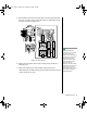
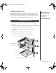
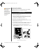
7. If you are not reinstalling a board in the same slot, install a slot cover
over the vacant slot. The tapered foot of the cover must fit into the
mating slot in the expansion slot frame.
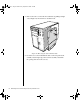
8. Replace the rear foam pad and the access panel (“Closing the System”
on page 7).
9. Running the SSU is optional after you install or remove a PCI or ISA
board.
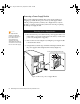
Power Supplies
The system can be configured with two or three power supply modules.
These configurations use a power share board that distributes the power
supplied by two supply modules to various system components. Table 5
shows the power distribution using the power share board. Configurations
using three power supply modules use the same power share board as those
using two supply modules. The third module acts as a hot spare and allows
hot swapping of failed power supply modules.
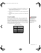
Table 5: Power Sharing
Power
Supply
Output
B System board 5V
A System board 3.3V
A System board 12v-1
B System board 12V-2
A Peripheral 5V
B Peripheral 12V
Warning!
Hazardous voltage, current,
and energy levels are
present inside the power
supply. There are no
user-serviceable parts inside
it; servicing must be done by
technically qualified
personnel.
3424.boo Page 65 Wednesday, September 2, 1998 9:23 AM