MAN US E4650 SYS GDE R0 10/01 Gateway® E-4650 System Manual
Contents Preface . . . . . . . . . . . . . . . . . . . . . . . . . . . . . . . . . . . . . . . . . . . . . . . . . . . . . . . . . . . . . . v Conventions used in this manual . . . . . . . . . . . . . . . . . . . . . . . . . . . . . . . . . . . . . . . v Getting additional information . . . . . . . . . . . . . . . . . . . . . . . . . . . . . . . . . . . . . . . . . . vi 1 Checking Out Your Gateway Computer . . . . . . . . . . . . . . . . . . . . . . . . . 1 Gateway Mid-Tower front . . . . . . . . . . . . .
Surge suppressors . . . . . . . . . . . . . . . . . . . . . . . . . . . . . . . . . . . . . . . . . . . . . . .51 Line conditioners . . . . . . . . . . . . . . . . . . . . . . . . . . . . . . . . . . . . . . . . . . . . . . . .52 Uninterruptible power supplies . . . . . . . . . . . . . . . . . . . . . . . . . . . . . . . . . . . . . .52 Power management . . . . . . . . . . . . . . . . . . . . . . . . . . . . . . . . . . . . . . . . . . . . . . . . .53 Using Standby mode . . . . . . . . . . . . . . . . . . .
Video problems . . . . . . . . . . . . . . . . . . . . . . . . . . . . . . . . . . . . . . . . . . . . . . . . . . . . 90 Error messages . . . . . . . . . . . . . . . . . . . . . . . . . . . . . . . . . . . . . . . . . . . . . . . . . . . . 92 Beep codes . . . . . . . . . . . . . . . . . . . . . . . . . . . . . . . . . . . . . . . . . . . . . . . . . . . . . . . 94 A Reference Data . . . . . . . . . . . . . . . . . . . . . . . . . . . . . . . . . . . . . . . . . . . . . . . . .
iv
Preface Conventions used in this manual Throughout this manual, you will see the following conventions: Convention Description ENTER Keyboard key names are printed in small capitals. CTRL+ALT+DEL A plus sign means to press the keys at the same time. Setup Commands to be entered, options to select, and messages that appear on your monitor are printed in bold. User’s Guide Names of publications are printed in italic.
Getting additional information Log on to the technical support area of www.gatewayatwork.com to find information about your computer or other Gateway products.
Checking Out Your Gateway Computer 1 This chapter provides basic information about your Gateway computer. Read this chapter to find out: ■ Where components and connectors are located ■ What accessories are available These illustrations show typical computer systems. Your computer system may not look exactly the same.
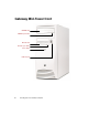
Gateway Mid-Tower front CD/DVD drive CD/DVD eject button Diskette drive Diskette eject button Power button USB 2.
Component CD/DVD drive Icon Description Use a CD drive for installing software programs, playing audio CDs, and accessing data. Use a DVD drive for installing software programs, playing audio CDs and DVDs, and accessing data. CD/DVD eject button Press this button to open the CD/DVD drive tray. Diskette drive Use this drive to store smaller files on diskettes. Diskette eject button Press this button to eject an inserted diskette. Power button Press this button to turn the power on or off.
Gateway Mid-Tower back Power connector Shipping screw Voltage selector switch Mouse port Keyboard port USB 1.1 ports Serial port Parallel port Network jack USB 2.
Component Icon Description Power connector Plug the power cable into this connector. Voltage selector switch Before turning on the computer, make sure that the switch is in the proper position for the correct power available. In the United States, the utility power is supplied at a nominal 115 volts at 60 Hz. The power supply is always set to this when the computer is operating in the United States. In other areas of the world, such as Europe, the utility power is supplied at 230 volts at 50 Hz.
Component Icon Description Joystick/MIDI port Plug a joystick or MIDI device into this port. Modem jack Plug a modem cable into this jack. Line out 2 (rear out) jack Rear Out. Plug powered speakers or an external amplifier into this jack. This jack is color-coded black. Line out 1 (speakers) jack Speakers. Plug powered speakers, an external amplifier, or headphones into this jack. This jack is color-coded green. Microphone jack Plug a microphone into this jack. This jack is color-coded red.
Heceta IV hardware management Heceta IV is an integrated data acquisition system that lets you monitor the status of your system hardware. Monitored information includes internal temperature, fan speed, voltage, and chassis intrusion (to alert you in the event of case cover removal). The features of the hardware management system can be accessed through LANDesk® Client Manager, which also provides a quick system health indicator.
8 Checking Out Your Gateway Computer
2 System Setup Setting up your computer Use the instructions on the Setup Poster that came with your computer to assemble your computer. You should prepare a safe working environment before assembling your computer by following these guidelines: ■ Use a clean, flat, and stable surface for your computer. Allow at least 6 inches at the rear of the computer for cabling and air circulation. ■ Obtain a grounded (three-prong) AC surge-protected power strip.
Starting your computer Before you start your computer for the first time: ■ Make sure that the voltage selector switch on the back of the computer is set to the correct voltage for your area. This switch is set at the factory to the correct voltage (see “Gateway Mid-Tower back” on page 4 for the voltage selector switch location). ■ Make sure all cables are firmly connected to the proper ports on the back panel of the computer.
Understanding the Power-On Self-Test When you turn on your computer, the Power-On Self-Test (POST) routine checks the computer memory and components. To see this information on the screen, press TAB during POST. Important The computer starts very quickly. If your monitor requires time to warm up, you may not see the messages. If you are having problems, you may need to wait for the monitor to warm up and then restart the computer. If you are trying to enter Setup, press F1 before the monitor warms up.
3 Continue following the instructions and selecting options in the start-up wizard dialog boxes, clicking Next to move through the dialog boxes, until the wizard tells you to restart the computer. If you need to return to the previous dialog box to change any of your entries, click Back. 4 Restart your computer. The setup is complete. Turning off your computer To turn off your computer: ■ In Windows XP, click Start, then click Turn Off Computer, then Turn Off.
Restarting your computer If your computer does not respond to keyboard or mouse input, you may have to close programs that are not responding. If closing unresponsive programs does not restore your computer to normal operation, you may have to restart the computer. To close unresponsive programs and restart your computer: 1 Press CTRL+ALT+DEL. A window opens that lets you close a program that is not responding.
14 System Setup
Working with the Gateway Mid-Tower case 3 Preventing static electricity discharge The components inside your computer are extremely sensitive to static electricity, also known as electrostatic discharge (ESD). Caution ESD can permanently damage electrostatic discharge sensitive components in the computer. Prevent ESD damage by following ESD guidelines every time you open the computer case.
■ Touch a bare metal surface on the back of the computer. ■ Unplug the power cord and modem cable. Before working with computer components, follow these guidelines: 16 ■ Avoid static-causing surfaces such as carpeted floors, plastic, and packing foam. ■ Remove components from their antistatic bags only when you are ready to use them. Do not lay components on the outside of antistatic bags because only the inside of the bags provide electrostatic protection.
Opening and closing The Gateway Mid-Tower case provides toolless access to internal components. Warning To avoid exposure to dangerous electrical voltages and moving parts, turn off your computer, then unplug the power and modem cords before opening the case. To open the Gateway Mid-Tower case: 1 Turn off the computer. 2 Following all static electricity discharge precautions, disconnect the power cord and all other cables. 3 Drain any residual power from the computer by pressing the power button.
6 Swing the side panel away from the case.
To close the Gateway Mid-Tower case: 1 For more stability, place the computer on its side. 2 Make sure all of the internal cables are arranged inside the case so they will not be pinched when you close the case.
3 Align the door tabs into the case notches. 4 Swing the side panel toward the case until the release levers lock. 5 Return the computer to its upright position. 6 Reconnect the cables and power cord.
Adding or replacing drives Preparing to add or replace a drive One 3.5-inch diskette drive, one 3.5-inch hard drive, and one CD drive are included with your computer. You can add one additional half-height 3.5-inch tape storage or disk storage device. As you prepare to install drives, keep the following in mind: ■ To remove and install drives, use an antistatic wrist strap. ■ If you remove a drive, place it in an antistatic bag or container.
Drive cabling information Your computer includes three different types of drive cables. Each drive cable is clearly labeled, indicating cable-type and showing which end is connected to the appropriate connector on the system board and which end is connected to the drive. Use the diskette drive connector cable to connect the diskette drive. Use the standard IDE connector cable to connect IDE devices such as CD drives and standard IDE hard drives.
3 If you are adding a new drive, press in on the two bezel release tabs, then swing open the front bezel.
4 If you are adding a new drive, remove the drive bay bezel cover for the bay into which you are installing the new drive. 3.5-inch drive bay bezel cover tab 24 Working with the Gateway Mid-Tower case 5.
5 If you are adding a new drive, remove the EMI shield for the bay into which you are installing the new drive. EMI shields 6 If you are replacing a drive, disconnect the drive cables, noting their locations and orientation. (You will reconnect the cables after you install the new drive.
7 If there is a shipping screw installed next to the release lever, remove the screw, then unlock the drive bay by sliding the release lever back toward the back of the case. 8 If you are replacing a drive, remove the old drive by sliding it forward and out of the drive bay.
9 Set any jumpers on the new drive. See the drive manual for further instructions. 10 Slide the new drive into the drive bay until it settles into the indentation, then lock it into place by sliding the release lever toward the front of the case. 11 Connect the drive cables according to the instructions in the drive manual. 12 Close the case by following the procedure “To close the Gateway Mid-Tower case:” on page 19.
To replace a hard drive: 1 Open the case by following the procedure “To open the Gateway Mid-Tower case:” on page 17. 2 Return the case to its upright position. 3 Disconnect the drive cables, noting their locations and orientation. (You will reconnect the cables after you install the new drive.) See the drive manual for further instructions.
4 Slide the green release lever out toward the open side of the case, then remove the drive by sliding it out of the drive bay. 5 Set any jumpers on the new drive. See the drive manual for further instructions. 6 Slide the new drive in and lock it into place by sliding the release lever toward the inside of the case. 7 Connect the drive cables according to the instructions in the drive manual. 8 Close the case by following the procedure “To close the Gateway Mid-Tower case:” on page 19.
Replacing expansion cards An expansion card is a card used in the computer to add functionality to the system. Use the following procedures to replace, add, or reseat an expansion card. To replace, add, or reseat an expansion card: 1 Open the case by following the procedure “To open the Gateway Mid-Tower case:” on page 17. 2 For more stability, place the computer on its side. 3 Disconnect any cables that are attached to the card, noting their locations and orientation.
5 While holding the expansion card retention cover open, remove the expansion card. You can slightly seesaw the card end-to-end to loosen the card, but do not bend the card sideways. Caution Do not touch the contacts on the bottom part of the expansion card. Touching the contacts can cause electrostatic damage to the card. 6 While holding the retention cover open, install the new card into the expansion slot.
7 Lock the card in place by pushing the expansion card retention cover inward, then secure the expansion card retention cover with the card retention cover thumb-screw. 8 Reconnect any cables to the card. 9 Close the case by following the procedure “To close the Gateway Mid-Tower case:” on page 19. 10 Refer to the guide that came with the card for any special software installation instructions.
Replacing the power supply To replace a Gateway Mid-Tower case power supply: 1 Open the case by following the procedure “To open the Gateway Mid-Tower case:” on page 17. 2 Return the computer to its upright position. 3 Disconnect the power supply cables from all components, noting their locations and orientation. (You will reconnect the cables after you install the new power supply.) 4 Flip the power supply retention clip out.
5 While supporting the power supply with your hand, remove the power supply by sliding it toward the front of the case, then outward. 6 Install the new power supply into the case by reversing the actions you took in Step 4, then lock the new power supply into place by flipping the power supply retention clip in. 7 Reconnect the power supply cables. 8 Close the case by following the procedure “To close the Gateway Mid-Tower case:” on page 19.
Replacing the system board To replace the system board: 1 Open the case by following the procedure “To open the Gateway Mid-Tower case:” on page 17. 2 Remove all of the expansion cards by following the procedure “To replace, add, or reseat an expansion card:” on page 30. 3 Disconnect the power and data cables from the system board, noting their locations and orientation. (You will reconnect the cables after you install the new board.) 4 Remove the thumb screw using a screwdriver, coin, or your fingers.
5 Remove the system board by sliding the board toward the front of the case. The system board standoffs slide out of the keyhole slots. Keyhole slot Standoff 6 Slide the new system board into the keyhole slots and lock it into place with the thumbscrew. Important The new system board must have special standoffs (pem studs) mounted on the bottom of the board. If necessary, use the standoffs from the original system board. 7 Connect the power and data cables.
Installing memory When you upgrade your computer memory, make sure that you install the correct type of memory module for your computer. For more information about your computer’s memory type, see “Specifications” on page 104. Installing or replacing RIMM memory You need to use a combination of Rambus Interface Memory Modules (RIMMs) and Continuity-RIMMs (C-RIMMs). All memory slots must be filled with either a RIMM or a C-RIMM. RIMMs RIMM memory has a metal cover on one or both sides of the module.
Tips & Tricks Identifying identical RIMM modules Identical RIMM modules must share the same five specifications shown in the example below. Number of RDRAMs ECC Support (blank = no ECC support Module Memory Capacity ECC = ECC support) 64MB/8 ECC RAMBUS 800-45 t RAC Memory Speed To install or replace RIMM or C-RIMM memory: 1 Open the case by following the procedure “Opening and closing” on page 17. Make sure that you remove all external cables and the power cord.
3 If you are removing a RIMM module from the memory module bank, gently pull the plastic tabs away from the sides of the memory module and remove it. - OR If you are removing a C-RIMM module from the memory module bank, gently pull the plastic tabs away from the sides of the module and remove it.
4 If you are installing two memory modules into one dual-channel (two slots per bank) bank (RIMM BANK 0), install two identical RIMMs in RIMM BANK 0 and two C-RIMMS in RIMM BANK 1 on the system board. RIMM BANK 0 RIMM modules RIMM BANK 1 C-RIMM modules - OR If you are installing four memory modules into two dual-channel banks (RIMM BANK 0 and RIMM BANK 1), install two identical RIMMs in RIMM BANK 0 and two identical RIMMs in RIMM BANK 1 on the system board.
5 Make sure that the tabs on the sides of the RIMM and C-RIMM secure the memory module in the slot. When the module is secure, you will hear a click as both tabs lock. 6 Close the case by following the procedure “To close the Gateway Mid-Tower case:” on page 19. 7 Turn on the computer. Windows starts and the Windows desktop appears. 8 In Windows XP, click Start, then select Control Panel, Performance and Maintenance, then System.
Replacing the battery The battery provides power for the computer real-time clock and CMOS memory, which stores the computer configuration information. If your battery is failing you may notice your computer clock slowing down and giving you the incorrect time. If so, open the BIOS Setup utility and make note of any custom values in the various menus before replacing the battery. Replacing the battery resets the BIOS Setup utility to its default values.
5 Locate the battery on the system board (see “System board layout” on page 98). The battery is circular and has the positive pole mark (+) on the top. 6 Place the edge of a small flat-head screwdriver under the battery and lift it up until it pops out of the socket. 7 Press the new battery in the socket with the positive pole up. Make sure you have pressed the battery down far enough for it to contact the base of the socket (it should snap into place).
44 Working with the Gateway Mid-Tower case
Using the BIOS Setup Utility 4 About the BIOS Setup utility The computer’s BIOS has a built-in setup utility that lets you configure several basic computer characteristics. The settings are stored in battery-backed RAM and are retained even when the power is off. Important The computer starts very quickly. If your monitor requires time to warm up, you may not see the messages. If you are having problems, you may need to wait for the monitor to warm up and then restart the computer.
Start the BIOS Setup utility by restarting the computer, then pressing F1 when the Gateway logo screen appears during startup. The Main BIOS Setup utility screen opens. It may not look exactly like the screen shown below. BIOS Setup Utility Maintenance Main Advanced Security AMI BIOS Version : XX.XX.
The main screen has the following menu selections at the top of the screen: ■ Maintenance lets you clear Setup passwords and enable extended configuration mode. The maintenance menu is only displayed when the BIOS configuration jumper is set to configure (see “Setting the BIOS configuration jumper” on page 49 for more information). ■ Main gives you access to basic information and settings related to your computer hardware and configuration.
Updating the BIOS If you need a new version of the BIOS, you can download the BIOS update from technical support area on the Gateway Web site (www.gatewayatwork.com) and install the new version from a diskette.
Setting the BIOS configuration jumper The system board has a configuration jumper related to the BIOS. Place a jumper on specific pins to reset the CMOS settings to the BIOS defaults or to erase a misplaced or forgotten password. For more information on the location and use of the configuration jumper, see “BIOS configuration jumper settings” on page 103. Caution Moving a jumper while the power is on can damage your computer.
50 Using the BIOS Setup Utility
Managing Your Computer 5 Protecting against power source problems Surge suppressors, line conditioners, and uninterruptible power supplies can help protect your computer against power source problems. Surge suppressors During a power surge, the voltage level of electricity coming into your computer can increase to far above normal levels and cause data loss or system damage.
When purchasing a surge suppressor: ■ Make sure the surge suppressor meets the appropriate product safety certification for your location, such as Underwriters Laboratories (UL). ■ Check the maximum amount of voltage the suppressor allows to pass through the line. The lower the voltage that the suppressor allows to pass through, the better the protection for your computer. ■ Check the energy absorption (dissipation) rating.
Power management Computer equipment can account for a significant portion of energy use in the home and office environment. You may not want to shut down your computer each time you leave it, especially if you plan to be away for only a short time.
Using Standby mode Always save your work before using the Standby mode. Once in Standby mode, your computer reduces or turns off the power to most devices except memory. However, the information in the memory is not saved to the hard drive. If power is interrupted, the information is lost. The table below shows how to use Standby mode. If your computer is... ...and you want to... ...then Off Start up Press the power button.
Changing power settings You can change power management settings, such as the power button function and power-saving timers, by changing power settings in Windows. You can also adjust power schemes and adjust advanced power settings. Power schemes (groups of power settings) let you change power saving options such as when the monitor or hard drive is automatically turned off. You can also select one of the defined power schemes or create a custom power scheme.
2 Click/Double-click the Power Options or Power Management icon. The Power Options Properties dialog box opens. 3 Select a power scheme from the Power Scheme list. - OR Set the timers for System standby, Turn off monitor, and Turn off hard disks, then save your custom power scheme by clicking Save As and typing a name for the scheme. 4 Save the changes by clicking OK.
Changing advanced power settings To change advanced power management settings: 1 In Windows XP, click Start, then select Control Panel. Click Performance and Maintenance. The Performance and Maintenance window opens. - OR In Windows Me, Windows 2000, or Windows 98, click Start, then select Settings, then Control Panel. The Control Panel window opens. If you do not see the Power Options or Power Management icon, click view all Control Panel options.
Activating Hibernate mode To activate Hibernate mode: 1 In Windows XP, click Start, then select Control Panel. Click Performance and Maintenance. The Performance and Maintenance window opens. - OR In Windows Me, Windows 2000, or Windows 98, click Start, then select Settings, then Control Panel. The Control Panel window opens. If you do not see the Power Options or Power Management icon, click view all Control Panel options. 2 Click/Double-click the Power Options or Power Management icon.
To place your computer into hibernation: ■ To use hibernation as a power savings mode, open the Power Options dialog box, click the Power Schemes or Advanced tab, select Hibernate as one of the power settings, then save the changes by clicking OK. ■ To manually place your computer into hibernation: ■ In Windows XP, click Start, then click Turn off computer, then hold the Shift key down while clicking Standby.
3 Click the UPS tab. 4 Click Select. The UPS Selection dialog box opens. 5 Select the manufacturer and model of the UPS device. 6 Click the serial port where the UPS device is attached. 7 Click Finish. 8 Click OK.
Protecting your computer from viruses A virus is a program that attaches itself to a file on a computer, then spreads from one computer to another. Viruses can damage data or cause your computer to malfunction. Some viruses go undetected for a period of time, because they are activated on a certain date. Protect your computer from a virus by: ■ Using your Norton® AntiVirus program to check files and programs that are on diskettes, attached to e-mail messages, or downloaded from the Internet.
To remove a virus: 1 Find and remove the virus immediately using Norton AntiVirus. 2 Turn off your computer and leave it off for at least 30 seconds. 3 Turn on the computer and rescan for the virus. To update Norton AntiVirus: 1 Click Start, then select All Programs, Norton AntiVirus, then LiveUpdate Norton AntiVirus. The LiveUpdate wizard opens. 2 Follow the on-screen instructions to update your Norton AntiVirus program with the latest virus protection files.
Managing hard drive space Windows provides several utilities you can use to manage your hard drive. Checking hard drive space Help and Support For more information on checking hard drive space, click Start, then select Help and Support or Help. To check hard drive space: 1 In Windows XP, click Start, then select My Computer. - OR In Windows Me, Windows 2000, or Windows 98, double-click the My Computer icon. 2 Right-click the drive that you want to check for available file space, then select Properties.
Using Disk Cleanup Delete unneeded files, such as temporary Windows files, to free hard drive space. Help and Support For more information on using Disk Cleanup, click Start, then select Help and Support or Help. To use the Windows Disk Cleanup program: 1 In Windows XP, click Start, then select My Computer. The My Computer window opens. - OR In Windows Me, Windows 2000, or Windows 98, double-click the My Computer icon. The My Computer window opens.
4 Select the check box beside each file type you want to delete. For more information about file types you can delete, read the descriptions in the Disk Cleanup dialog box. 5 Click OK, then click Yes. Checking the hard drive for errors The Error-checking program in Windows XP and Windows 2000 or ScanDisk program in Windows Me and Windows 98 examines the hard drive for physical flaws and file and folder problems.
3 Click the Tools tab. 4 Click Check Now. 5 Select the options to use, then click Start. For help, press F1. Windows checks the drive for errors. This process may take several minutes. 6 Correct any problems that are found by following the on-screen instructions. After Windows has finished checking the drive for errors, it provides a summary of the problems that it found. 7 Click OK.
Defragmenting the hard drive When working with files, sometimes Windows divides the file information into pieces and stores them in different places on the hard drive. This is called fragmentation, and it is normal. In order for the computer to use a file, Windows must search for the pieces of the file and put them back together. This process slows the hard drive performance.
3 Click the Tools tab. 4 Click Defragment Now. 5 If Disk Defragmenter does not start automatically, click Start or Defragment. 6 Disk Defragmenter shows its progress on the screen. When finished, Disk Defragmenter asks if you want to quit the program. 7 Click Close or Yes.
Backing up files Backing up files and removing them from the hard drive frees space for new files on the hard drive. It also protects you from losing important information if the hard drive fails or you accidentally delete files. You should back up your files regularly to a writable CD (if you have a CD-R or CD-RW drive) or to diskettes. Use a backup device, such as a CD-R, CD-RW, or Zip drive, to do a complete hard drive backup.
Using the Scheduled Task Wizard The Scheduled Task Wizard lets you schedule maintenance tasks such as running Disk Defragmenter and Error-checking or ScanDisk. Help and Support For more information on using the Scheduled Task Wizard, click Start, then select Help and Support or Help. To start the Scheduled Task Wizard: 1 Click Start, then select All Programs, Accessories, System Tools, then Scheduled Tasks. The Scheduled Tasks window opens. 2 Double-click Add Scheduled Task.
Cleaning your computer Keeping your computer clean and the vents free from dust helps keep your system performing at its best.
Cleaning the keyboard You should clean the keyboard occasionally by using an aerosol can of air with a narrow, straw-like extension to remove dust and lint trapped under the keys. If you spill liquid on the keyboard, turn off the computer and turn the unit upside down. Let the liquid drain, then let the keyboard dry before trying to use it again. If the keyboard does not work after it dries, you may need to replace it.
To clean your mouse: 1 Turn the mouse upside down. 2 Rotate the retaining ring on the bottom of the mouse counter-clockwise. 3 Remove the retaining ring and mouse ball. 4 Remove any dust, lint, or dirt from the mouse ball with a soft cloth. 5 Clean the mouse rollers with a cotton swab dipped in isopropyl alcohol. 6 Replace the mouse ball and lock the retaining ring into place.
Checking system health with LANDesk LANDesk® Client Manager is a desktop management interface (DMI) that lets you monitor the health of your system components. Through LANDesk, you can view software and hardware properties. You can also set LANDesk to notify you when system resources reach certain levels. To install LANDesk Client Manager: 1 In the C:\DMI folder on your hard drive, double-click the Setup icon to launch the install wizard. 2 Follow the instructions that appear on the screen.
System recovery Take advanced precautions that will allow you to restart your system and recover damaged files in the event that your hard drive is damaged, or your BIOS or system files get corrupted. Creating a startup diskette If your computer hard drive is damaged, you may not be able to start the computer from the hard drive. A startup diskette is a bootable diskette that enables you to start the computer and attempt to fix the problem.
76 Managing Your Computer
6 Troubleshooting Introduction If your computer does not operate correctly, re-read the instructions for the procedures you have performed. If an error occurs within a program, consult the documentation supplied with the program. This section identifies solutions to some possible problems. Troubleshooting checklist Before turning on the computer, make sure that: ■ The power cord is connected to the AC power-in connector and an AC outlet. ■ The AC outlet is supplying power.
Troubleshooting guidelines As you troubleshoot your computer, keep the following guidelines in mind: ■ Never remove the case cover while the computer is turned on. ■ Do not attempt to open the monitor. Even if the power is disconnected, stored energy in the monitor components can inflict a painful or harmful shock. ■ If a peripheral does not work, make sure that all of the connections are secure. ■ If you see an error message on the screen, write it down, word for word.
■ Turn off the computer, remove the cover, and make sure that all cables inside the case are attached securely. Also, make sure that the colored cable edges are aligned correctly and that the connectors do not miss any pins. Disconnect and reconnect the cables. Close the case as described on page 17, then turn on the computer. ■ Turn off the computer, remove the cover and, if you have the proper test equipment, make sure that the new battery has power.
CD drive problems An audio CD produces no sound. Probable cause Solution The CD is loaded incorrectly Make sure the label is facing up, then try again. The speakers are not connected Make sure the speaker cables are connected properly and securely. The speaker volume is turned down Check the volume control and turn it up if necessary. The speakers may be muted through the Multimedia volume control Make sure mute controls are turned off.
An audio CD will not play. Probable cause Solution The CD is loaded incorrectly Make sure the label is facing up, then try again. The CD is scratched or dirty Try cleaning the CD with a lint-free cloth. Make sure the CD is not scratched. The computer does not recognize the CD drive. Probable cause Solution The CD is not intended for PC use Make sure the CD is PC-compatible. The CD drive needs to be added as new hardware In the Control Panel window, double-click Add New Hardware.
Computer problems The computer will not start up. Probable cause Solution The computer is not connected to an AC outlet Make sure the power cable(s) are connected correctly to an operating AC power source. The voltage selection switch is not set correctly Make sure the voltage selection switch is set correctly for your area. The computer is non-responsive. Probable cause Solution An error occurred while running a program or your computer may be out of memory Restart your computer.
The mouse does not work. Probable cause Solution The mouse is not plugged in or connected properly Make sure the cable is plugged in correctly. The mouse driver did not load when the computer started Load the appropriate mouse driver manually or contact Gateway Technical Support. The mouse is defective Try a mouse that you know is working.
Diskette drive problems The computer does not recognize the diskette drive. Probable cause Solution The diskette drive may be configured incorrectly Restart your computer, then press F1 to open the BIOS Setup utility. In the Advanced | Diskette Configuration menu, make sure that the diskette drive parameters are set correctly. The drive cables are not connected properly Open the computer and make sure all cables are correctly connected to the system board.
Hard drive problems The computer does not recognize the IDE drive. Probable cause Solution The primary IDE device may be configured incorrectly Restart your computer, then press F1 to open the BIOS Setup utility. From the Advanced | IDE Configuration menu, set the IDE Controller to Both and the Primary IDE Master to Auto. The drive may not be configured properly Consult the hard drive user’s guide for instructions on how to configure the drive. Configure the drive correctly.
Memory problems The computer detected memory errors during start up. 86 Probable cause Solution Memory was added or removed, and the new configuration was not saved in BIOS Setup utility Open the BIOS Setup utility and save the new memory configuration. The memory was installed incorrectly Make sure the memory is seated and oriented correctly. A memory chip is faulty Replace the card with the faulty chip. Third-party diagnostic programs can help determine which chip or memory segment is failing.
Modem problems The computer does not recognize the modem. Probable cause Solution The modem has not been added as new hardware Add the modem as new hardware. The modem is not connected to a live phone jack Make sure the line connected to the modem is working and plugged into the appropriate port on the modem (line port).
Peripheral/adapter problems The computer does not recognize an adapter card. 88 Probable cause Solution The interrupt or I/O address is set incorrectly Check the address configuration of the adapter card and make sure that it does not conflict with another card in the computer. The card was not configured through the software Configure the card with the appropriate software. The card was not installed correctly Make sure that the jumpers are configured correctly, then reseat the card.
Printer problems The printer will not turn on. Probable cause Solution The printer is not plugged in Make sure the power cable is plugged into a working power source. The printer is not turned on Make sure the printer’s power switch is pressed or set to the On position. If the printer is turned on, the green power LED should be illuminated. The printer is defective Try another printer, if one is available. The printer is turned on but will not print.
Video problems The computer is running but the screen is blank. Probable cause Solution The monitor is not turned on Make sure the monitor is plugged in and turned on. If the monitor is turned on, the green power LED should illuminate. The monitor’s data cable is not connected Make sure the monitor data cable is connected to the video controller on the back of the computer. The connector or cable is damaged Check the connector and cable for bent or damaged pins.
The color monitor displays everything in black and white. Probable cause Solution The computer was turned on before the monitor Make sure the monitor is turned on, then restart the computer. The display type is set incorrectly In the Control Panel window, double-click Display, set the display to the appropriate video type and resolution, then restart the computer. The displayed characters are garbled.
Error messages This section lists common error messages that you may see. These messages often indicate procedural errors such as an incorrect keystroke or a write-protected diskette. Some messages, however, may indicate a problem that requires you to consult the troubleshooting section of this manual. 92 Error message Description GA20 Error An error occurred with Gate A20 when switching to protected mode during the memory test.
Error message Description FDC Failure Error occurred trying to access diskette drive controller. HDC Failure Error occurred trying to access hard disk controller. Memory Size Decreased Memory size has decreased since the last boot. If no memory was removed, then memory may be bad. Memory Size Increased Memory size has increased since the last boot. If no memory was added, there may be a problem with the system. Memory Size Changed Memory size has changed since the last boot.
Beep codes Whenever a recoverable error occurs during POST, the BIOS displays an error message describing the problem. The BIOS also issues a beep code (one long tone followed by two short tones) during POST if the video configuration fails (a faulty video card or no card installed) or if an external ROM module does not properly checksum to zero. An external ROM module (for example, a video BIOS) can also issue audible errors, usually consisting of one long tone followed by a series of short tones.
If POST completes normally, the BIOS issues one short beep before passing control to the operating system.
96 Troubleshooting
Reference Data A Intel 850 ATX System Board Technical Reference Features This FC-PGA2 system board uses the Intel® 850 chipset. The system board supports: ■ Direct RAMBUS® RDRAM RIMM system memory ■ Intel® Pentium® 4 processors ■ Ultra ATA 33/66/100 drives ■ 100 MHz Front Side Bus (FSB) (400 MHz Data Bus) ■ 4x AGP ■ ACPI 1.0b power management ■ Integrated Intel 802.
System board layout The following illustration shows the system board divided into two sections: 1 2 98 Reference Data
Section 1 A B C D E F G Intel 850 ATX System Board Technical Reference 99
A USB front panel header (2.
Section 2 A B C D H I E J F G K Q O M L N P R Intel 850 ATX System Board Technical Reference 101
A Primary IDE cable connector B Secondary IDE cable connector C Auxiliary power connector D Memory expansion slots E Processor socket F Auxiliary power connector G Intruder header H Diskette drive cable connector I Main power connector J Auxiliary fan connector K Processor fan connector L Personal System/2™ (PS/2) mouse port M PS/2 keyboard port N USB ports (1.1) O Serial (COM) connector P Parallel (LPT) printer connector Q Network jack R USB ports (2.
BIOS configuration jumper settings The BIOS configuration jumper lets you clear passwords or recover your BIOS if it becomes corrupted. For information about the location of this jumper, see “Section 1” on page 99.
Specifications The following specifications are for the standard configuration. Your system may contain optional equipment. All specifications are subject to change without notice or obligation. Supported processors Intel® Pentium® 4 processors utilizing 478-pin FC-PGA2 connector Chipset Intel 850 Memory 184-pin, 2.5V, PC800 Direct Rambus Interface Memory Modules (RIMMs). Two channels. Four slots. Expandable to 2 GB (with 512 Mb technology). BIOS AMI BIOS. Flash BIOS for easy updates from diskette.
Environment Operating temperature: 10°C to 35°C (50°F to 95°F) Humidity: 20% to 80% Altitude: -60.96 m to 3048 m CPU clearance: >10.16 mm after installation, top and sides Many products for Gateway and its subsidiaries are custom engineered by our suppliers to Gateway specifications and may vary from similarly marketed products.
106 Reference Data
Safety, Regulatory, and Legal Information B Important safety information Your Gateway system is designed and tested to meet the latest standards for safety of information technology equipment. However, to ensure safe use of this product, it is important that the safety instructions marked on the product and in the documentation are followed. Warning Always follow these instructions to help guard against personal injury and damage to your Gateway system.
■ Some products are equipped with a three-wire power cord to make sure that the product is properly grounded when in use. The plug on this cord will fit only into a grounding-type outlet. This is a safety feature. If you are unable to insert the plug into an outlet, contact an electrician to install the appropriate outlet.
Regulatory compliance statements United States of America Federal Communications Commission (FCC) Unintentional emitter per FCC Part 15 This device has been tested and found to comply with the limits for a Class B digital device, pursuant to Part 15 of the FCC rules. These limits are designed to provide reasonable protection against harmful interference in a residential installation.
(applicable to products fitted with USA modems) Your modem complies with Part 68 of the Federal Communications Commission (FCC) rules. On the computer or modem card is a label that contains the FCC registration number and Ringer Equivalence Number (REN) for this device. If requested, this information must be provided to the telephone company. An FCC-compliant telephone line cord with a modular plug is required for use with this device.
Canada Industry Canada (IC) Unintentional emitter per ICES-003 This digital apparatus does not exceed the Class B limits for radio noise emissions from digital apparatus as set out in the radio interference regulations of Industry Canada. Le présent appareil numérique n’émet pas de bruits radioélectriques dépassant les limites applicables aux appareils numériques de Classe B prescrites dans le règlement sur le brouillage radioélectrique édicté par Industrie Canada.
European Union The following information is only applicable to systems labeled with the CE mark .
Japan VCCI statement This equipment is in the Class B category (Information Technology Equipment to be used in a residential area or an adjacent area thereto) and conforms to the standards set by the Voluntary Control Council for Interference by Information Technology Equipment aimed at preventing radio interference in such residential areas. When used near a radio or TV receiver, it may become the cause of radio interference. Read instructions for correct handling.
Australia and New Zealand EMI statement This device has been tested and found to comply with the limits for a Class B digital device, pursuant to the Australian/New Zealand standard AS/NZS 3548 set out by the Australian Communications Authority and the Radio Spectrum Management Agency.
Laser safety statement All Gateway systems equipped with CD and DVD drives comply with the appropriate safety standards, including IEC 825. The laser devices in these components are classified as “Class 1 Laser Products” under a US Department of Health and Human Services (DHHS) Radiation Performance Standard. Should the unit ever need servicing, contact an authorized service location.
Television antenna connectors protection (for systems fitted with TV/cable TV tuner cards) External television antenna grounding If an outside antenna or cable system is to be connected to your Gateway PC, make sure that the antenna or cable system is electrically grounded to provide some protection against voltage surges and static charges.
Warning When installing or realigning an outside antenna system, extreme care should be taken to keep from touching such power lines or circuits. Contact with them could be fatal.
Notices Copyright © 2001 Gateway, Inc. All Rights Reserved 4545 Town Centre Court San Diego, CA 92121 USA All Rights Reserved This publication is protected by copyright and all rights are reserved. No part of it may be reproduced or transmitted by any means or in any form, without prior consent in writing from Gateway. The information in this manual has been carefully checked and is believed to be accurate. However, changes are made periodically.
Index Numerics 3.
line out 6 MIDI 6 modem 6 monitor (VGA) 5 network 5 parallel 5 power 5 PS/2 keyboard 5 PS/2 mouse 5 serial 5 speaker out 6 USB 3, 5 cover removing 17 replacing 17 cover release lever 6 creating startup diskettes 75 D deleting files and folders 64 Disk Cleanup 64 Disk Defragmenter 67 diskette drive 3 cabling information 22 eject button 3 installing 21 preparing to install 21 removing 21 replacing 21 troubleshooting 84 drive cabling information 22 CD/DVD 3 diskette 3 preparing to install 21 replacing 3.
LANDesk Heceta IV 7 Hibernate mode 3, 53, 58, 59 humidity protecting the computer 9 I installing 3.
adjusting 10 port 5 troubleshooting 90 mouse cleaning 73 port 5 troubleshooting 83 N network jack 5 Norton Antivirus 61 O opening the case 17 operating system setting up 11 P parallel port 5 peripheral devices troubleshooting 88 ports game 6 joystick 6 MIDI 6 monitor 5 parallel 5 PS/2 keyboard 5 PS/2 mouse 5 serial 5 USB 3, 5 POST (power-on self-test) 11 power advanced settings 55, 57 BIOS Setup utility menu 47 button 3, 10, 12, 13 changing advanced settings 57 changing modes 54 changing schemes 55 chang
case cover 17 CD/DVD drive 21 diskette drive 21 expansion card 30 front bezel 23 hard drive 21 main board 35 memory 37 power supply 33 system board 35 resetting the computer 13 restoring LANDesk Client Manager 74 system 75 Resume mode 3 RIMM memory 37 S safety battery warnings 42 general precautions 107 saving system configuration settings 75 ScanDisk 65 Scheduled Tasks Wizard 70 security menu BIOS Setup utility 47 serial port 5 setting up computer 9 operating system 11 safety precautions 107 Windows 11 Se
U uninterruptible power supply (UPS) 52, 59 updating the BIOS 48 USB port 3, 5 utility software BIOS Setup utility 45 V video troubleshooting 90 virus 61 protecting against 61 removing with Norton AntiVirus 61 voltage selector switch 5 W warning battery 42 Windows resetting the computer 13 setup 11 124 Index
MAN US E4650 SYS GDE R0 10/01 Gateway® E-4650 System Manual