MAN US E5400 SYSTEM GDE R0 11/99 *8505030* *8505030* *8505030* 8505030 E-5400 Mid Tower System Manual
05030.book Page i Monday, November 22, 1999 8:23 AM Contents Preface . . . . . . . . . . . . . . . . . . . . . . . . . . . . . . . . . . . . . . . . . . . . . . . . . . . . . . . . . . . . . . v Conventions used in this manual . . . . . . . . . . . . . . . . . . . . . . . . . . . . . . . . . . . . . . . . v Getting additional information . . . . . . . . . . . . . . . . . . . . . . . . . . . . . . . . . . . . . . . . . . . vi System Features . . . . . . . . . . . . . . . . . . . . . . . . . . . . . . . . .
05030.book Page ii Monday, November 22, 1999 8:23 AM Removing and replacing the hard drive . . . . . . . . . . . . . . . . . . . . . . . . . . . . . . 49 Installing an additional hard drive . . . . . . . . . . . . . . . . . . . . . . . . . . . . . . . . . . . 50 Power supply . . . . . . . . . . . . . . . . . . . . . . . . . . . . . . . . . . . . . . . . . . . . . . . . . . . . . . . 52 Removing and replacing the power supply . . . . . . . . . . . . . . . . . . . . . . . . . . . . 52 System fans . . . . . .
05030.book Page iii Monday, November 22, 1999 8:23 AM Hard drive problems . . . . . . . . . . . . . . . . . . . . . . . . . . . . . . . . . . . . . . . . . . . . . . . . . 89 Memory/Processor problems . . . . . . . . . . . . . . . . . . . . . . . . . . . . . . . . . . . . . . . . . . 90 Modem problems . . . . . . . . . . . . . . . . . . . . . . . . . . . . . . . . . . . . . . . . . . . . . . . . . . . . 91 Peripheral/Adapter problems . . . . . . . . . . . . . . . . . . . . . . . . . . . . . . . . . . . . .
05030.
05030.book Page v Monday, November 22, 1999 8:23 AM Preface Conventions used in this manual Throughout this manual, you will see the following conventions: Convention Description ENTER Keyboard key names are printed in small capitals. CTRL+ALT+DEL A plus sign means to press the keys at the same time. Setup Commands to be entered, options to select, and messages that appear on your monitor are printed in bold. User’s Guide Names of publications are printed in italic.
05030.book Page vi Monday, November 22, 1999 8:23 AM Important A note labeled important informs you of special circumstances. Caution A caution warns you of possible damage to equipment or loss of data. Warning A warning indicates the possibility of personal injury. Getting additional information Log on to the Gateway Support Center at www.gateway.com/support to find information about your system or other Gateway products.
05030.book Page 1 Monday, November 22, 1999 8:23 AM 1 System Features Standard features ■ Up to two Intel® Pentium III processors with 133 MHz Front Side Bus (FSB) in Slot 1 processor sockets ■ Four Rambus™ In-line Memory Module (RIMM™) sockets that support up to 2 Gigabytes (GB) of Rambus Dynamic Random Access Memory (RDRAM) up to 400 Mhz ■ Intel 840 chipset ■ Integrated Intel 82259 10/100 LAN support with Cape lookout ■ AGP Slot (AGP 2.
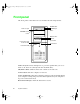
05030.book Page 2 Monday, November 22, 1999 8:23 AM Front panel The front panel of the mid-tower case includes the following features: CD/DVD drive Audio-out jack CD/DVD eject button CD-ROM volume control Diskette drive Power button and Power-on LED Diskette eject button Reset button Hard drive LED Audio-out jack connects headphones or powered speakers that you use to listen to an audio CD (directly from the CD/DVD drive). CD/DVD volume control controls the volume of an audio CD.
05030.book Page 3 Monday, November 22, 1999 8:23 AM CD/DVD drive plays data or audio CDs. CD/DVD eject button ejects a CD from the CD/DVD drive. Diskette drive writes to and reads from 3.5-inch, 1.44 MB diskettes. Diskette eject button ejects diskettes from the diskette drive. Reset button restarts a system that has become non-responsive.
05030.book Page 4 Monday, November 22, 1999 8:23 AM Rear panel The mid-tower case rear panel includes the following Input/Output (I/O) ports, connectors, and switches: Power connector Padlock tab Voltage selector Thumbscrew Mouse port Keyboard port USB ports Parallel port Serial port RJ-45 LAN connector Audio Line-out Microphone-in Secondary video port Primary video port Audio Line-in Thumbscrew Kennsington lock slot Voltage selector sets the voltage for your area, either 115 V or 230 V.
05030.book Page 5 Monday, November 22, 1999 8:23 AM Serial port connects to a serial device. RJ-45 LAN connector lets you connect to a network, and the adjacent Indicator LEDs show LAN activity (yellow) and 100 Mbit speed (green). Microphone-in, Audio Line-out, and Audio Line-in jacks connect audio devices such as speakers, tape players, and microphones. Secondary video port connects the second monitor interface cable. Primary video port connects the first (or only) monitor interface cable.
05030.book Page 6 Monday, November 22, 1999 8:23 AM System board The following figure and list identify system board components.
05030.
05030.
05030.book Page 9 Monday, November 22, 1999 8:23 AM 2 System Setup Setting up your system Use the instructions on the poster that came with your system to assemble your system. You can prepare a safer working environment before assembling your system by following the guidelines listed below. ■ Provide a clean, flat, and stable surface for your system. Allow at least 12 inches at the rear of the computer for cabling and air circulation. ■ Obtain a grounded (three-prong) AC surge-protected power strip.
05030.book Page 10 Monday, November 22, 1999 8:23 AM Starting your system Before you start your system for the first time: ■ Make sure that the voltage selector switch on the back of the computer is still set to the correct voltage for your area. This switch is set at the factory to the correct voltage (see “Rear panel” on page 4 for voltage selector switch location). ■ Make sure all cables are firmly connected to the proper ports on the rear panel of the computer.
05030.book Page 11 Monday, November 22, 1999 8:23 AM 3 Turn on the computer by pressing its power button. The light-emitting diode (LED) in the power button is lit when the power is on. Power button and power LED 4 Turn on any other components connected to the computer, such as speakers, a printer, or a scanner.
05030.book Page 12 Monday, November 22, 1999 8:23 AM Understanding the Power-On Self-Test When you turn on your computer, the power-on self-test (POST) routine checks the system memory and components. To see this information on the screen, press TAB during POST. Press ESC to bypass the remaining memory count. The system displays an error message if POST finds any problems. Write down the error message that appears.
05030.book Page 13 Monday, November 22, 1999 8:23 AM Turning off your system Every time you turn off your system, shut down the operating system first. You may lose data if you do not follow the proper procedure. To turn off your system in Windows NT: 1 Click Start, then click Shut down the computer? (Windows NT), then select Shut Down. 2 Click OK. The computer turns off. If you see a message saying It is now safe to turn off your computer, turn off the computer by pressing the power button.
05030.book Page 14 Monday, November 22, 1999 8:23 AM Resetting your system If your computer does not respond to keyboard or mouse input, you may have to close a program or programs that may not be responding. If closing unresponsive programs does not restore your computer to normal operation, you may have to reset the system. To reset your system in Windows NT: 1 Press CTRL+ALT+DEL. A window opens that lets you to close a program that is not responding.
05030.book Page 15 Monday, November 22, 1999 8:23 AM 3 Case Access Preventing static electricity Before opening the computer case, read and follow these precautions to prevent damage from static electricity. When opening your computer case, always perform the following procedure. Caution Static electricity can permanently damage electronic components in your computer. Prevent electrostatic damage to your computer by following static electricity precautions every time you open your computer case.
05030.book Page 16 Monday, November 22, 1999 8:23 AM Also follow these static electricity precautions: 16 ■ Avoid static-causing surfaces such as plastic and styrofoam in your work area. ■ Remove the parts from their antistatic bag or container only when you are ready to use them. Do not lay parts on the outside of an antistatic bag or container because only the inside provides antistatic protection. ■ Always hold cards by their edges and their metal mounting brackets.
05030.book Page 17 Monday, November 22, 1999 8:23 AM Opening the case Important All references to front, rear, left or right on the computer are based on the computer being in a normal, upright position, as viewed from the front.
05030.book Page 18 Monday, November 22, 1999 8:23 AM 3 Slide the left side panel to the rear (approximately 3/4-inch), disengaging the retaining tabs on the top edge of the panel from the top of the chassis. Thumbscrews 4 Lift the panel up and away from the chassis.
05030.book Page 19 Monday, November 22, 1999 8:23 AM To remove the bezel: 1 With the left side panel removed, disengage the retention tabs on the left side of the bezel by prying outward on each tab. 2 Swing the bezel out from the front of the chassis and disengage the hinge tabs on the right side of the bezel by moving the bezel to the right. 3 Remove the bezel.
05030.book Page 20 Monday, November 22, 1999 8:23 AM Closing the case Replace the chassis cover as soon as you finish installing or removing components so that dust and dirt (which can damage the computer) do not collect inside the computer. To replace the bezel: 1 Holding the bezel at an angle to the front of the chassis, place the hinge tabs on the right side of the bezel in the appropriate slots in the front of the chassis.
05030.book Page 21 Monday, November 22, 1999 8:23 AM To replace the chassis cover: 1 Holding the left side panel at an angle to the chassis and 3/4-inch to the rear, engage the retaining strip on the bottom edge of the panel with the lip at the bottom edge of the chassis. 2 Swing the top of the panel toward the chassis, engaging the retaining tabs on the top edge of the side panel with the slots on the chassis. 3 Slide the panel toward the front of the chassis 3/4-inch, securing it into place.
05030.
05030.book Page 23 Monday, November 22, 1999 8:23 AM 4 System Components The system board The system board is the heart of the computer, which integrates the other elements of the system, such as the processor, memory, storage, networking, and communications, and lets them operate in a coordinated and useful way. Removing the system board The system board is mounted on stand-off retention hooks on the right side of the chassis.
05030.book Page 24 Monday, November 22, 1999 8:23 AM 4 Remove all expansion cards from the system board (See “Adding an expansion card” on page 34). 5 Disconnect all cables from the system board, including the power cables from the power supply. Note where the cables are connected. 6 Remove the retaining screw securing the board to the right side of the chassis.
05030.book Page 25 Monday, November 22, 1999 8:23 AM 7 Loosen the retaining screw at the back (right side) of the chassis. System board retaining screw 8 Slide the system board toward the front of the chassis slightly, to disengage it from the stand-off retention hooks (see illustration under “To install the system board:”), then remove it carefully. 9 Remove the system board mounting bracket (shown below) and place the board in a static-free bag or container.
05030.book Page 26 Monday, November 22, 1999 8:23 AM To install the system board: 1 Install the system board mounting bracket on the rear edge of the system board by inserting the tabs into the corresponding holes in the board and rotating the bracket into place.
05030.book Page 27 Monday, November 22, 1999 8:23 AM 2 Holding the system board by the top and bottom edges, place it in the case by aligning the mounting holes on the board with the stand off (threaded) and stand off retention hooks on the right side of the case. 3 Holding the system board in place, tighten the retaining screw on the right rear of the case. 4 Replace the retention screw previously removed from the system board, then tighten the screw until the board is secured.
05030.book Page 28 Monday, November 22, 1999 8:23 AM Replacing or adding a processor The system is compatible with the Intel ® Pentium® III 667 and 733 MHz and faster processors with 133 MHz front-side bus (FSB). Up to two processors may be installed in the system. When replacing a processor, or adding an additional processor, order a Pentium III processor upgrade kit from Gateway. The kit includes the Pentium III processor, a fan/heatsink, and a disposable electrostatic wrist strap.
05030.book Page 29 Monday, November 22, 1999 8:23 AM 6 Repeat the previous two steps for the other side of the processor. 7 Pull the processor up and out of the slot. 8 Align the new processor with the processor slot (note that the processor slot is keyed so the processor can only be installed one way) and press firmly to install it.
05030.book Page 30 Monday, November 22, 1999 8:23 AM 9 Reconnect the power supply cable of the processor fan to the CPU fan connector on the system board. 10 Close the case, as described in Chapter 3. 11 Reconnect the power cord and all other cords you removed, then turn on the system. To add an additional processor: 1 Turn off the system and disconnect the power cord and modem cord (if installed) and all other external peripheral devices. 2 Open the case by following the instructions on page 17.
05030.book Page 31 Monday, November 22, 1999 8:23 AM ■ RIMM modules must be installed symetrically into both channels, that is, if a RIMM is installed in RIMM-1 (Channel A), the same size, density, type, and speed RIMM must be installed in RIMM-3 (Channel B), likewise for RIMM-2 and RIMM-4. If RIMMs are not installed in this manner, the computer will not boot. Using the encoded part numbers on the RIMM modules is the best way to make sure that the parts are the same.
05030.book Page 32 Monday, November 22, 1999 8:23 AM 4 - 96 MB RIMMs 384 MB 2 - 128 MB RIMMs, 2 - 96 MB RIMMs 448 MB 4 - 128 MB RIMMs 512 MB 2 - 256 MB RIMMs, 2 - 128 MB RIMMs 768 MB 4 - 256 MB RIMMs 1 GB 2 - 512 MB RIMMs, 2 - 256 MB RIMMs 1.5 GB 4 - 512 MB RIMMs 2 GB To add or remove RIMMs: 1 Turn off the system and disconnect the power cord and modem cord (if installed) and all other external peripheral devices. 2 Open the case by following the instructions on page 17.
05030.book Page 33 Monday, November 22, 1999 8:23 AM 3 If you are adding a RIMM, pull open the socket clamps on each side of the RIMM socket and remove the CRIMM. Socket clamps 4 If you are replacing a RIMM, pull open the socket clamps on each side of the RIMM socket, then lift the RIMM out of the socket. RIMM 5 Store the RIMM in a static-free container.
05030.book Page 34 Monday, November 22, 1999 8:23 AM 6 Insert the new RIMM into the socket and align the two notches in the RIMM with the two notches in the RIMM socket. RIMM 7 Gently press the RIMM into the socket until it’s firmly seated. Inserting the RIMM automatically locks each of the socket clamps on each end of the RIMM. 8 Close the case, as described in Chapter 3. 9 Reconnect peripherals, the modem cord, and the power cord, then turn on the system.
05030.book Page 35 Monday, November 22, 1999 8:23 AM 2 Open the case by following the instructions on page 17. (See “Preventing static electricity” on page 15.) 3 Locate an available slot and remove the slot cover by removing the screw that secures it to the back of the chassis. 4 Insert the bottom edge of the expansion card (the keyed edge with the contacts) into the slot on the system board and push in firmly to seat the card.
05030.book Page 36 Monday, November 22, 1999 8:23 AM You may need to reconfigure your system after installing some expansion cards. You may also need to install software that came with the card. Check the card documentation for additional information. Replacing the battery The battery provides power for the system real-time clock and CMOS memory, which holds the system configuration information. If your battery is failing you may notice your system clock slowing down and giving you the incorrect time.
05030.book Page 37 Monday, November 22, 1999 8:23 AM 6 Using a small, flat-bladed screwdriver, carefully remove the battery from its socket on the system board. 7 Press the new battery in the socket with the positive pole up. Be sure you have pressed the battery down far enough for it to contact the base of the socket (it should snap into place). 8 Close the case, as described in Chapter 3. 9 Reconnect peripherals, the modem cord, and the power cord, then turn on the system.
05030.book Page 38 Monday, November 22, 1999 8:23 AM 38 ■ Turn off the computer, remove the cover, and make sure that all cables inside the case are attached securely. Also, make sure that the colored cable edges are aligned correctly and that the connectors didn’t miss any pins. Disconnect and reconnect the cables. Close the case as described in Chapter 3, reconnect the modem and power cords, then turn on the computer.
05030.book Page 39 Monday, November 22, 1999 8:23 AM Preparing to replace or add a drive One 3.5-inch diskette drive, one 3.5-inch hard drive, and one CD-ROM drive are included with your computer. You can add additional drives of the following types: ■ Half-height 3.5-inch diskette drives - The floppy controller supports up to two diskette drives, one of which is the 3.5-inch diskette drive that comes with your computer. ■ Half-height 3.
05030.book Page 40 Monday, November 22, 1999 8:23 AM As you prepare to install drives, keep the following in mind: 40 ■ To remove and install drives, you need a grounding wrist strap and a Phillips screwdriver. ■ If you remove a drive, place it in an antistatic bag or container. ■ Before you install a drive, see the drive’s documentation for information on configuring the drive, setting any jumpers on the drive, and attaching cables to the drive.
05030.book Page 41 Monday, November 22, 1999 8:23 AM Drive cabling information Three drive cables are included with your system. The diskette drive connector cable is used to connect diskette drives and other non-IDE devices such as tape backup drives. The two IDE connector cables are used to connect IDE devices such as CD-ROM drives and hard drives.
05030.book Page 42 Monday, November 22, 1999 8:23 AM 3.5-inch diskette or CD/DVD drives Removing and replacing the 3.5-inch diskette or CD/DVD drive To replace the drives: 1 Turn off the system and disconnect the power cord and modem cord (if installed) and all other external peripheral devices. 2 Open the case by following the instructions on page 17. (See “Preventing static electricity” on page 15.) 3 Remove the bezel, as described in “To remove the bezel:” on page 19. 4 Locate the 3.
05030.book Page 43 Monday, November 22, 1999 8:23 AM Both the 3.5-inch diskette drive and 5.25-inch CD/DVD drives are secured in the chassis by sets of removable rails. The rails let the drives slide into and out of the guides in the front bays. Extra rails are included with your system and are clipped to the outsides of the drive cages, inside the case.
05030.book Page 44 Monday, November 22, 1999 8:23 AM Installing an additional 3.5-inch device The second, externally accessible 3.5-inch drive bay can be used to install a 3.5-inch device such as a tape drive, a 100 MB or 120 MB disk storage device, or an additional 3.5-inch diskette drive. Extra sets of rails are included with your system (clipped to the drive cage) and are used for the installation.
05030.book Page 45 Monday, November 22, 1999 8:23 AM 7 Align the rails with the open bay, and slide the drive into the chassis until the locking tabs snap into place. 8 Connect the power and data cables to the back of the drive. (See drive documentation for proper drive jumper settings and cable orientation.) 9 Close the case, as described in Chapter 3. 10 Reconnect the power and modem cords, then turn on the system. 11 Run the configuration software, if required. 3.
05030.book Page 46 Monday, November 22, 1999 8:23 AM Installing an additional 5.25-inch device Two additional, externally accessible 5.25-inch drive bays can be used to install additional 5.25-inch devices such as a CD-ROM writer or a tape backup. Extra sets of rails are included with your system (clipped to the drive cage) and are used for the installation.
05030.book Page 47 Monday, November 22, 1999 8:23 AM 5 Remove the metal EMI shield from the front of the drive bay, if installed, by placing a finger in the hole on the left side of the shield and pulling out to disengage it from the chassis. Metal EMI shield Pull out on the left side of the metal EMI shield Caution Your system was designed to adhere to electromagnetic interference requirements and the shield is an integral part of the system.
05030.book Page 48 Monday, November 22, 1999 8:23 AM 7 Align the rails with the bay, and slide the drive into the chassis until the locking tabs snap into place. 8 Connect the power and data cables, making sure the cables match their original position. (See your drive documentation for proper drive jumper settings and cable orientation.) 9 Close the case, as described in Chapter 3. 10 Reconnect the power and modem cords, then turn on the system. 11 Run the configuration software, if required.
05030.book Page 49 Monday, November 22, 1999 8:23 AM Hard drives Removing and replacing the hard drive The hard drive that is included with your system is mounted in the bottom drive cage in the chassis. To replace the hard drive: 1 Turn off the system and disconnect the power cord and modem cord, if installed. 2 Open the case by following the instructions on page 17. (See “Preventing static electricity” on page 15.) 3 Locate the 3.5-inch hard drive in the bottom drive cage.
05030.book Page 50 Monday, November 22, 1999 8:23 AM 7 Place the old drive in an antistatic bag or container, then place the new hard drive on a static-free surface with the top up and the connectors facing you. 8 Install two small, plastic drive mounting rails (“L” rail on the left and “R” rail on the right) to the new hard drive, making sure the front rail extensions are towards the front of the device.
05030.book Page 51 Monday, November 22, 1999 8:23 AM To install an additional hard drive: 1 Turn off the system and disconnect the power cord and modem cord, if installed. 2 Open the case by following the instructions on page 17. (See “Preventing static electricity” on page 15.) 3 Place the new hard drive on a static-free surface with the top up and the connectors facing you.
05030.book Page 52 Monday, November 22, 1999 8:23 AM Power supply Removing and replacing the power supply To remove the power supply: 1 Turn off the system and disconnect the power cord and modem cord, if installed. 2 Open the case by following the instructions on page 17. (See “Preventing static electricity” on page 15.) 3 Lay the case on its right side, if possible. 4 Locate and disconnect the power supply connectors from all internal devices, including the 3.
05030.book Page 53 Monday, November 22, 1999 8:23 AM 6 Locate and remove the two supporting screws securing the power supply to the top of the chassis. Screws Screws 7 While supporting the power supply with one hand, locate and remove the two screws securing the power supply to the rear of the chassis.Carefully lift the power supply out of the chassis. To install the new power supply: 1 Before installing the new power supply, verify that it matches the one you previously removed.
05030.book Page 54 Monday, November 22, 1999 8:23 AM 4 Replace the two screws securing the power supply to the back of the chassis, leaving them slightly loose. 5 Replace the two supporting screws securing the power supply to the top of the chassis, then tighten all screws. 6 Reconnect the power connectors to the system board and to all internal devices. 7 Place the case upright, then close the case as described in Chapter 3. 8 Reconnect the power and modem cords, then turn on the system.
05030.book Page 55 Monday, November 22, 1999 8:23 AM System fans Removing and replacing the system fans The front system fan is mounted on the front of the bottom drive cage. The rear system fan is mounted on a fan mounting bracket attached to the rear of the system. To remove the front system fan: 1 Turn off the system and disconnect the power cord and modem cord, if installed. 2 Open the case by following the instructions on page 17. (See “Preventing static electricity” on page 15.
05030.book Page 56 Monday, November 22, 1999 8:23 AM 7 Remove the plastic card guide attached to the bottom drive cage by depressing the locking tabs (from the rear of the guide) and pivoting the top of the guide toward the back of the system. (You may have to remove one or more add-in cards from the system board.) Tab 8 Remove the two screws securing the bottom drive cage to the front of the chassis and the two screws securing it to the right side of the chassis.
05030.book Page 57 Monday, November 22, 1999 8:23 AM 9 Slide the bottom drive cage toward the left side of the chassis, then toward the back, disengaging it from the middle drive cage and the chassis. 10 Carefully remove the bottom drive cage from the chassis. 11 Remove the four screws securing the front system fan to the bottom drive cage and lift the fan from the cage. Note the routing of the fan power cable.
05030.book Page 58 Monday, November 22, 1999 8:23 AM To install the new front system fan: 1 Place the new front system fan into the recess in the front of the bottom drive cage. Orient the fan with the label toward the inside of the chassis (toward the system board), and the fan power cable to the right side of the drive cage. 2 Secure the fan to the drive cage with the four screws previously removed.
05030.book Page 59 Monday, November 22, 1999 8:23 AM 4 Depress the two locking tabs on the plastic fan bracket (from the back of the chassis), then move the fan bracket to the left (from the inside) to disengage the four retaining tabs from the back of the chassis.
05030.book Page 60 Monday, November 22, 1999 8:23 AM 5 Carefully remove the fan and bracket from the chassis. 6 Remove the fan from the bracket by carefully prying up on each corner with a flat-bladed screwdriver. 7 Remove the fan guard by removing the four screws securing it to the fan. To install the new rear system fan: 1 Install the fan guard on the new fan with the four screws you removed from the old fan. 2 Place the new fan into the recess in the rear fan bracket and press it firmly into place.
05030.book Page 61 Monday, November 22, 1999 8:23 AM 3 Replace the fan bracket unit into the chassis by engaging the four retaining tabs with the holes in the back of the chassis and sliding the unit to the right until the two locking tabs click into place. 4 Plug the fan power cable into the appropriate connector on the system board. 5 Close the case as described in Chapter 3. 6 Reconnect the power and modem cords, then turn on the system.
05030.book Page 62 Monday, November 22, 1999 8:23 AM Control panel Removing and replacing the control panel To remove the control panel: 1 Turn off the system and disconnect the power cord and modem cord, if installed. 2 Open the case by following the instructions on page 17. (See “Preventing static electricity” on page 15.) 3 Remove the bezel, as described in “To remove the bezel:” on page 19. 4 After noting the position of the cables, disconnect the front panel connector from J13J2 on the system board.
05030.book Page 63 Monday, November 22, 1999 8:23 AM 5 Pull out on the retention tab and slide the control panel unit to the left, then pull it away from the front of the chassis, taking care not to damage the control panel cables or connectors as you pull them from the chassis. Retention tab (shown with part of bracket cut away for clarity) To install the new control panel: 1 Feed the control panel connector and cables through the opening in the front of the chassis.
05030.book Page 64 Monday, November 22, 1999 8:23 AM 3 Insert the mounting tabs of the control panel unit into the proper slots on the front of the chassis, then slide the unit to the right until it locks into place. 4 Replace the bezel and close the case as described in Chapter 3. 5 Reconnect the power and modem cords, then turn on the system.
05030.book Page 65 Monday, November 22, 1999 8:23 AM Using the BIOS Configuration Manager 5 About the BIOS Configuration Manager The computer’s BIOS has a built-in configuration manager that lets you configure several basic system characteristics. The settings are stored in battery-backed RAM and are retained even when the power is off. Enter the BIOS Configuration Manager by restarting the computer, then selecting Enter Setup with your mouse when the Gateway Logo screen appears.
05030.book Page 66 Monday, November 22, 1999 8:23 AM BIOS Configuration Manager Help System Processors System Memory Boot Options System Even < > BIOS Configuration Manager General Help Copyright (c) 1999 Intel Corporation Copyright (c) 1985-1998 American Megatrends Inc. Tab Navigation: Use the left mouse button or Left/Right Arrow keys to select a tab. Use the scroll buttons (upper right corner) to display additional tabs.
05030.book Page 67 Monday, November 22, 1999 8:23 AM ■ Boot Options gives you access to information and settings for boot features and boot sequences. ■ System Event Log provides information on event log capability and validity, as well as event log options. Allows the user to view the event log. ■ Integrated IDE lets you to enable or disable the integrated IDE controller. Also lets you enable, disable or configure, primary and secondary drives. Lets you change the spin delay.
05030.book Page 68 Monday, November 22, 1999 8:23 AM Updating the BIOS Flash memory simplifies distributing BIOS upgrades. If you need a new version of the BIOS, you can download the BIOS update from technical support on the Gateway Web site and install the new version from a diskette.
05030.book Page 69 Monday, November 22, 1999 8:23 AM To update the BIOS: 1 Place the bootable diskette containing the BIOS files into drive A: then restart the computer. 2 The BIOS update program will run. 3 The BIOS update program will let you know what to expect when you attempt to update the BIOS and will give you a choice to update or not. Select Y to update the BIOS. 4 The system will automatically reboot and find the wpgbios.bin file on the diskette, then it will load the file to update the BIOS.
05030.book Page 70 Monday, November 22, 1999 8:23 AM Setting the system board jumpers The J1F2 configuration jumper on the system board lets you clear passwords and recover the BIOS. (See the figure on page 6 for the location of the jumper.) The table below shows the settings required to perform those tasks. Make sure you turn off the computer and unplug the power cord before moving the jumper. Caution Moving the jumper while the computer’s power is on can damage your computer.
05030.book Page 71 Monday, November 22, 1999 8:23 AM 3 Remove the jumper from the J1F2 (See “System board” on page 6 for location) and set it aside. You will use it in a later step. 4 Close the case (see “Closing the case” on page 20 for instructions), then reconnect the power cord. 5 Place the previously created bootable diskette containing the BIOS files into drive A:, then turn on the computer. The recovery process may take a few minutes.
05030.
05030.book Page 73 Monday, November 22, 1999 8:23 AM Managing Your System 6 Protecting against power source problems Surge suppressors, line conditioners, and uninterruptible power supplies can help protect your system against power source problems. Surge suppressors During a power surge, the voltage level of electricity coming into your system can increase far above normal levels and cause data loss or system damage.
05030.book Page 74 Monday, November 22, 1999 8:23 AM ■ Check the energy absorption, or dissipation, rating. The higher the energy absorption rating, the better the protection for your system. ■ Check for line-conditioner capabilities. A line conditioner smooths out some of the normal line noise (small voltage fluctuations) of an electrical supply. Line conditioners A line conditioner protects your system from the small daily fluctuations in voltage from an electrical supply.
05030.book Page 75 Monday, November 22, 1999 8:23 AM Maintain and manage your hard drive Regular maintenance can keep your hard drive operating efficiently and good file management can keep your system free of unwanted files while making important files secure and easier to find. Hard drive maintenance utility By regularly using Check Disk, you can help maintain the performance of your hard drive.
05030.book Page 76 Monday, November 22, 1999 8:23 AM Hard drive management practices By deleting unneeded files from your hard drive and managing the space that is automatically allocated for saving certain files, you can help maintain the performance of the hard drive. Checking hard drive space In Windows, you can see a chart of the available hard drive space. To check hard drive space: 1 Double-click on the My Computer icon on the desktop. The My Computer window opens.
05030.book Page 77 Monday, November 22, 1999 8:23 AM To delete temp files: 1 Open Windows Explorer, and select Tools, Find, then Files and Folders. 2 In the Named text box, type *.tmp 3 In the Look in drop down list, select your drive letter. 4 Click Find Now. The list of temp files appears. 5 Click Modified above the list. To see the Modified button, you may need to maximize the Find window. The list is sorted by date. 6 Highlight all the files in the list except those with today’s date.
05030.book Page 78 Monday, November 22, 1999 8:23 AM To decrease the size of the Recycle Bin: 1 Right-click the Recycle Bin, then select Properties from the pop-up menu. 2 At the Global tab, select either Configure drives independently or Use one setting for all drives. 3 If you are configuring drives independently, click the tab for the drive you want to configure. 4 Move the slider to set the size of the Recycle Bin. 5% is a good initial setting. 5 Click OK.
05030.book Page 79 Monday, November 22, 1999 8:23 AM System integrity It’s important to protect your system against electrical problems and physical hazards such as heat, moisture, and dust. It’s also important to protect it against less obvious hazards such as viruses and hardware overloads. Protecting your computer from viruses A virus is a program that attaches itself to a program or data file on a computer, then spreads from one computer to another.
05030.book Page 80 Monday, November 22, 1999 8:23 AM Monitoring system health with LANDesk Intel LANDesk® Client Manager is a desktop management interface (DMI) that lets you monitor the health of your system components. Through LANDesk, you can view software and hardware properties. You can also set LANDesk to notify you when system resources reach certain levels. To install LANDesk Client Manager: 1 Double-click the Setup icon in the c:\dmi folder on your hard drive. The InstallShield® wizard starts.
05030.book Page 81 Monday, November 22, 1999 8:23 AM System Recovery In the event that your hard drive is damaged, or if your BIOS or system files get corrupted, it’s important to take advanced precautions that will allow you to restart your system and recover damaged files. Creating a startup diskette If your computer hard drive is damaged, you may not be able to start the computer from the hard drive.
05030.
05030.book Page 83 Monday, November 22, 1999 8:23 AM 7 Cleaning Your System Cleaning the mouse If the mouse pointer on the screen moves erratically when you move the mouse, the inside of the mouse may be dirty. To clean the mouse: 1 Turn off the computer, then disconnect the mouse cable from the mouse port. 2 Turn your mouse upside down and remove the roller ball cover. 3 Cup your hand under the mouse and turn your mouse right-side up. The roller ball should drop into your hand.
05030.book Page 84 Monday, November 22, 1999 8:23 AM Cleaning the keyboard You should clean the keyboard occasionally to free it of dust and lint particles trapped under the keys. The easiest way to do this is to blow trapped dirt from under the keys using an aerosol can of air with a narrow, straw-like extension. If you spill liquid on the keyboard, turn off the computer, then disconnect it. Turn the keyboard upside down to let the liquid drain.
05030.book Page 85 Monday, November 22, 1999 8:23 AM 8 Troubleshooting Introduction If your system does not operate correctly, re-read the instructions for the procedures you have performed. If an error occurs within an application, consult the documentation supplied with the software. This section identifies solutions to some possible problems.
05030.book Page 86 Monday, November 22, 1999 8:23 AM Troubleshooting checklist Before turning on the system, make sure that: ■ The power cord is connected to the AC power-in connector and an AC outlet. ■ The AC outlet is supplying power. ■ If a power strip is used it is turned on, setting the circuit breaker. ■ The voltage selection switch on the system power supply reflects the proper voltage.
05030.book Page 87 Monday, November 22, 1999 8:23 AM CD/DVD problems An audio CD produces no sound Probable Cause Solution The CD/DVD is loaded incorrectly. Make sure that the label is facing upward, then try again. The speakers are not connected. Make sure that the speaker cables are connected properly and securely. The speaker volume is turned down. Check the volume control. The speakers may be muted via the Multimedia volume control.
05030.book Page 88 Monday, November 22, 1999 8:23 AM 88 Probable Cause Solution The CD/DVD drive needs to be added as new hardware. From the Control Panel window (Start | Settings | Control Panel), double-click Add New Hardware. Follow the directions for adding the drive. If you are not experienced with this procedure, call Gateway Client Care. The secondary IDE device may be disabled. Restart your computer, then press F1 to enter the BIOS Setup utility program.
05030.book Page 89 Monday, November 22, 1999 8:23 AM Hard drive problems The SCSI drive is not recognized by the system Probable Cause Solution The SCSI bus is not properly terminated. Make sure that the last device on the SCSI chain is properly terminated. The drive is configured with a conflicting SCSI address. Change the device’s SCSI address to one that is not currently being used by the system. The cables are not connected correctly. Open the system, then check the cable connections.
05030.book Page 90 Monday, November 22, 1999 8:23 AM Memory/Processor problems Memory errors were detected during system start up Probable Cause Solution Memory was added or removed, and the new configuration was not saved in BIOS Setup utility. Enter the BIOS Setup utility and save the new memory configuration. The memory was installed incorrectly. Check the memory for proper seating and orientation. A memory chip is faulty. Replace the card on which the faulty chip resides.
05030.book Page 91 Monday, November 22, 1999 8:23 AM Modem problems The modem is not recognized by the system Probable Cause Solution The modem has not been added as new hardware. Add the modem as new hardware. The modem is not connected to a live phone jack. Make sure that the line connected to the modem is live and plugged into the appropriate port on the modem (line port). The phone jack is shared by another modem or telephone.
05030.book Page 92 Monday, November 22, 1999 8:23 AM Peripheral/Adapter problems A SCSI device is not recognized by the system Probable Cause Solution The device needs to be added as new hardware. From the Control Panel window (Start | Settings | Control Panel), double-click Add New Hardware. Follow the directions for adding the device. If you are not experienced with this procedure, call technical support. The SCSI ID may be invalid. Assign an available SCSI ID to the device.
05030.book Page 93 Monday, November 22, 1999 8:23 AM The diskette drive will not read, write, or format Probable Cause Solution The diskette is not IBM-formatted. Make sure that the diskette you are trying to format is IBM compatible. If it is, try reformatting it. The disk is write protected. Make sure that the write-protection window on the upper-right corner of the diskette is closed (unprotected). The diskette is corrupted. Run ScanDisk on the diskette.
05030.book Page 94 Monday, November 22, 1999 8:23 AM Printer problems The printer will not turn on Probable Cause Solution The printer is not turned on. Make sure that the printer’s power switch is depressed or set to the On position. If power is applied to the printer, the green power LED should be illuminated. The printer is not plugged in. Check the power cable. Make sure that it is plugged into a live power source. The printer is defective. Try another printer, if one is available.
05030.book Page 95 Monday, November 22, 1999 8:23 AM System problems The system will not start up Probable Cause Solution The system is not connected to an AC outlet. Make sure that the power cable is connected to an AC power source. Voltage selection switch not set correctly. Make sure that the voltage selection switch is set to the correct power source. The system is non-responsive Probable Cause Solution An error occurs during an application or your system may be out of memory.
05030.book Page 96 Monday, November 22, 1999 8:23 AM The mouse does not work 96 Probable Cause Solution The mouse is not plugged in or connected properly. Check the cable. Make sure that it is plugged in correctly. The mouse driver did not load when the system started. Load the appropriate mouse driver manually or contact technical support. The mouse is defective. Try a mouse you know is working.
05030.book Page 97 Monday, November 22, 1999 8:23 AM Video problems The system is running but there is no display Probable Cause Solution The monitor is not turned on. Make sure that the monitor is plugged in and turned on. If power is applied to the monitor, the green power LED should illuminate. The monitor’s data cable is not connected. Make sure that the monitor’s data cable is connected to the video controller on the back of the system. The connector or cable is damaged.
05030.book Page 98 Monday, November 22, 1999 8:23 AM The text on the display is dim or difficult to read Probable Cause Solution The monitor’s brightness and contrast controls are turned down. Adjust the brightness and contrast knobs until the text becomes clear. Sunlight is glaring off the display. Position the monitor away from the sun or window. The monitor may be old. Replace the monitor.
05030.book Page 99 Monday, November 22, 1999 8:23 AM The video is distorted Probable Cause Solution The monitor’s controls are not properly adjusted. Adjust the monitor controls until the text becomes clear. (See your monitor documentation for more information.) The connector or cable is damaged. Check the connector and cable for bent or damaged pins. The surge protector or UPS is damaged. Disconnect the monitor power cable, then connect it directly to the power source.
05030.book Page 100 Monday, November 22, 1999 8:23 AM Error messages This section lists common error messages that may appear on your monitor. These messages often indicate procedural errors such as an incorrect keystroke or a write-protected diskette. Some messages, however, may indicate a problem that requires you to consult the troubleshooting section of this manual. 100 Error Message Solutions Access denied. Try saving to a new file or diskette.
05030.book Page 101 Monday, November 22, 1999 8:23 AM Error Message Solutions Diskette drive reset failed. Enter the BIOS Setup utility, then verify the diskette drive parameters. Check the diskette drive cables. Make sure Pin 1 on the cable aligns with Pin 1 on the connector. Diskette read failed - strike F1 to retry boot. Make sure that the boot disk contains the Command.com file. Use the configuration utility (if applicable) to make sure that your drive or controller configuration.
05030.book Page 102 Monday, November 22, 1999 8:23 AM 102 Error Message Solutions Invalid password. Enter your password again, making certain to enter it correctly. If you do not know the password, you may need to reinstall the software you are trying to access. Startup passwords are stored in BIOS. If this password has been set and is unknown, you may be able to reset the password via system board jumper settings. Keyboard clock line failure. Try a working keyboard.
05030.book Page 103 Monday, November 22, 1999 8:23 AM Error Message Solutions Print queue is full. Wait until the current print job has completed before sending another print job. If you receive this error often, you need to add memory to the printer. Printer is out of paper. Add paper to the printer. Make sure that the printer is online. Required parameter missing. Make sure that you entered the right command. If you are trying to exit MS-DOS to return to Windows, type exit, then press ENTER.
05030.
05030.book Page 105 Monday, November 22, 1999 8:23 AM Safety, Regulatory, and Notices 9 Important safety Information Your Gateway system is designed and tested to meet the latest standards for safety of information technology equipment. However, to ensure safe use of this product, it is important that the safety instructions marked on the product and in the documentation are followed. Warning Always follow these instructions to help guard against personal injury and damage to your Gateway system.
05030.book Page 106 Monday, November 22, 1999 8:23 AM Setting up your system ■ Read and follow all instructions marked on the product and in the documentation before you operate your system. Retain all safety and operating instructions for future use. ■ Do not use this product near water or a heat source such as a radiator. ■ Make sure you set up the system on a stable work surface. ■ The product should only be operated from the type of power source indicated on the rating label.
05030.book Page 107 Monday, November 22, 1999 8:23 AM Replacement parts and accessories Use only replacement parts and accessories recommended by Gateway. Important Caution Do not use Gateway products in areas classified as hazardous locations. Such areas include patient care areas of medical and dental facilities, oxygen-laden environments, or industrial facilities. To reduce the risk of fire, use only No. 26 AWG or larger telecommunications line cord.
05030.book Page 108 Monday, November 22, 1999 8:23 AM Regulatory compliance statements American users FCC Part 15 This device has been tested and found to comply with the limits for a Class B digital device, pursuant to Part 15 of the FCC rules. These limits are designed to provide reasonable protection against harmful interference in a residential installation.
05030.book Page 109 Monday, November 22, 1999 8:23 AM FCC part 68 (applicable to products fitted with USA modems) Your modem complies with Part 68 of the Federal Communications Commission (FCC) rules. On the computer or modem card is a label that contains the FCC registration number and Ringer Equivalence Number (REN) for this device. If requested, this information must be provided to the telephone company. An FCC-compliant telephone line cord with a modular plug is required for use with this device.
05030.book Page 110 Monday, November 22, 1999 8:23 AM Canadian users ICES-003 This digital apparatus does not exceed the Class B limits for radio noise emissions from digital apparatus as set out in the radio interference regulations of Industry Canada. Le présent appareil numérique n’émet pas de bruits radioélectriques dépassant les limites applicables aux appareils numériques de Classe B prescrites dans le règlement sur le brouillage radioélectrique édicté par Industrie Canada.
05030.
05030.book Page 112 Monday, November 22, 1999 8:23 AM Japanese users VCCI statement This equipment is in the Class B category (Information Technology Equipment to be used in a residential area or an adjacent area thereto) and conforms to the standards set by the Voluntary Control Council for Interference by Information Technology Equipment aimed at preventing radio interference in such residential areas. When used near a radio or TV receiver, it may become the cause of radio interference.
05030.book Page 113 Monday, November 22, 1999 8:23 AM Australia and New Zealand users EMI statement This device has been tested and found to comply with the limits for a Class B digital device, pursuant to the Australian/New Zealand standard AS/NZS 3548 set out by the Australian Communications Authority and Radio Spectrum Management Agency.
05030.book Page 114 Monday, November 22, 1999 8:23 AM Laser safety statement All Gateway systems equipped with CD and DVD drives comply with the appropriate safety standards, including IEC 825. The laser devices in these components are classified as “Class 1 Laser Products” under a US Department of Health and Human Services (DHHS) Radiation Performance Standard. Should the unit ever need servicing contact an authorized service location.
05030.
05030.book Page 116 Monday, November 22, 1999 8:23 AM Notices Copyright © 1999 Gateway, Inc. All Rights Reserved 4545 Town Centre Court San Diego, CA 92121 USA All Rights Reserved This publication is protected by copyright and all rights are reserved. No part of it may be reproduced or transmitted by any means or in any form, without prior consent in writing from Gateway. The information in this manual has been carefully checked and is believed to be accurate. However, changes are made periodically.
05030.book Page 117 Monday, November 22, 1999 8:23 AM Appendix System specifications The following specifications are for the standard configuration; your system may contain optional equipment. All specifications are subject to change. Case size Width: 8.25-inch Depth: 18.625-inch Height: 19.125-inch Processors Intel® Pentium III™ processors operating at 500 MHz and faster Cache 512K on processor RAM Four RIMM sockets on the system board support 2.
05030.book Page 118 Monday, November 22, 1999 8:23 AM 118 I/O ports One parallel port, one serial port, two USB ports, one PS/2 keyboard port, one PS/2 mouse port, one microphone-in jack, one audio line-in jack, one audio line-out jack, one RJ-45 network jack Expansion slots Five PCI slots Drive Bays Three 5.25-inch drive bays (one occupied by CD-ROM drive), two external 3.5-inch drive bays (one occupied by diskette drive), and four 3.5-inch internal drive bays (one occupied by included hard drive).
05030.book Page 119 Monday, November 22, 1999 8:23 AM Index Numerics 3.5-inch device, installing additional 44 5.
05030.book Page 120 Monday, November 22, 1999 8:23 AM New Zealand users 113 file backup 76 files, deleting unneeded 76 front bezel removing 19 replacing 20 front panel 2 G General tab, BIOS Configuration Manager 67 guidelines, troubleshooting 86 H hard drive adding additional 50 installing 49 LED (light-emitting diode) 2 maintenance 75 maintenance utilities 75 management 76 replacing 49 troubleshooting 89 Help tab, BIOS Configuration Manager 66 I IDE drive, cabling 41 installing 3.
05030.
05030.
MAN US E5400 SYSTEM GDE R0 11/99 *8505030* *8505030* *8505030* 8505030 E-5400 Mid Tower System Manual