USER GUIDE Gateway® E-824R/E-826R SuperLoader™ 3
Contents Chapter 1: Introduction . . . . . . . . . . . . . . . . . . . . . . . . . . . . . . . . . . . . . . . . . . . . . . . . . . . . . .1 Introduction . . . . . . . . . . . . . . . . . . . . . . . . . . . . . . . . . . . . . . . . . . . . . . . . . . . . . . . . . . . . . Features . . . . . . . . . . . . . . . . . . . . . . . . . . . . . . . . . . . . . . . . . . . . . . . . . . . . . . . . . . . . . . . . . Gateway E-824R DLT-V4 SuperLoader 3 . . . . . . . . . . . . . . . . . . . . . . . . . . . . . .
Contents www.gateway.com Installing a magazine blank . . . . . . . . . . . . . . . . . . . . . . . . . . . . . . . . . . . . . . . . . .43 Removing a magazine . . . . . . . . . . . . . . . . . . . . . . . . . . . . . . . . . . . . . . . . . . . . . . .43 Removing a magazine blank . . . . . . . . . . . . . . . . . . . . . . . . . . . . . . . . . . . . . . . . .43 Changing the orientation of a magazine or magazine blank . . . . . . . . . .44 Manually operating the magazine . . . . . . . . . . . . . . . . .
www.gateway.com Contents Running diagnostic tests remotely . . . . . . . . . . . . . . . . . . . . . . . . . . . . . . . . . . . . . . 70 Diagnostics using On-board Remote Management . . . . . . . . . . . . . . . . . . 70 Checking for errors . . . . . . . . . . . . . . . . . . . . . . . . . . . . . . . . . . . . . . . . . . . . . . . . . . . . . 70 Hard error log display . . . . . . . . . . . . . . . . . . . . . . . . . . . . . . . . . . . . . . . . . . . . . . . 74 Error code field description . . . . .
Contents iv www.gateway.
CHAPTER 1 Introduction • Introduction • Features • Enclosure components • Getting Help 1
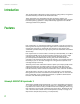
CHAPTER 1: Introduction www.gateway.com Introduction This guide provides information on the installation, configuration, and general use of the Gateway® E-824R and E-826R autoloaders. These autoloaders are compatible with most operating systems and environments that support the SCSI interface, but require either direct support from the operating system or a compatible backup application to take full advantage of their many features.
www.gateway.com Features Gateway E-826R LTO-3 SuperLoader 3 The Gateway E-826R LTO-3 SuperLoader 3 is SCSI-3 compatible and operates as a single SCSI ID/two LUN data storage device. It is equipped with an LTO-3 tape drive and contains as many as sixteen Ultrium 3 data cartridges, when using two magazines, which provides a compressed capacity of 6.4 Terabytes of data and a sustained data transfer rate of 245 GB per hour (native), or as high as 490 GB per hour compressed (assuming 2:1 compression).
CHAPTER 1: Introduction www.gateway.
www.gateway.
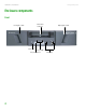
CHAPTER 1: Introduction www.gateway.com Product components # Accessory 1 SCSI cable 2 SCSI terminator 3 Power cable 4 Setup poster 5 CD (documentation) 6 Magazine blank 7 Bar code labels 8 TORX T8 and T10 L-key drivers Getting Help In addition to your autoloader’s documentation, you can use the following information resources to help you use your autoloader.
www.gateway.com Getting Help Gateway Web site Gateway provides a variety of information on its Web site to help you use your autoloader. Visit the Gateway Web site at support.gateway.
CHAPTER 1: Introduction 8 www.gateway.
CHAPTER 2 Installing and Setting Up your Autoloader • Overview • Preparation • Installation • Setup 9
Chapter 2: Installing and Setting Up your Autoloader www.gateway.com Overview Preparation 1 Prepare to install your new E-824R or E-826R (see “Preparation” on page 10). 2 Identifying the correct SCSI bus types (see “SCSI bus requirements” on page 10). Installation 1 Install the autoloader in a computer rack. (see “Rack mounting the autoloader” on page 13). 2 Connect the autoloader to the server. (see “Connecting the SCSI and power cables” on page 20).
www.gateway.com Preparation Choosing a location Choose a location that meets the following criteria. The autoloader uses standard rack mounting hardware and must be flat and level. Criteria Description Rack requirements Standard 19-inch rack with 2U (3.5 inches) of available rack space. Room temperature 50–95° F (10–35° C) Power source AC power voltage: 100–127 VAC; 200–240 VAC Line frequency: 50–60 Hz Locate the AC outlet near the autoloader.
Chapter 2: Installing and Setting Up your Autoloader www.gateway.com Overloading the circuit When you connect the autoloader to the electrical supply circuit, do not overload the circuit. Reliable grounding Make sure that the electrical circuit providing power to your autoloader has a reliable ground. Pay particular attention to supply connections other than direct connections to the branch circuit, such as the use of power strips.
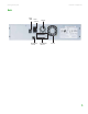
www.gateway.com Installation Installation Rack mounting the autoloader The autoloader can be rack mounted using the V-rail kit (included). The following illustration shows minimum clearances for rack mount installation: Tape magazine 27.0” (686 mm) Minimum clearance to load or unload a magazine from the system Minimum clearance to load a tape through the mailslot Clearance to door inside a rack 6.0” (152 mm) Tape 2.
Chapter 2: Installing and Setting Up your Autoloader www.gateway.com General preparation for rack mount installation To prepare for rack mount installation: Warning Failure to take these safety steps may result in personal injury or equipment damage. 1 Lower the cabinet feet. 2 Extend the cabinet’s anti-tip device, if available. An anti-tip device may be extendable legs or similar equipment used to stabilize the cabinet.
www.gateway.com Installation Left rail assembly Right rail assembly Accessory pieces Besides the rail parts themselves, there are two plates included with the rail kit. These plates are used for various rack mountings. The front cover plate is used on all rack rails. The 10-32 inside nut plate is used on the .375 inch square-hole rails, the .280 diameter rails, and the M6 rails. Front cover plate used on all rack rails 10-32 inside nut plate used on .375 square-hole rails, and .
Chapter 2: Installing and Setting Up your Autoloader www.gateway.com Installation in a .375 square-hole rack To install the rail in a .375 square-hole rack: 1 Identify the correct mounting holes on the vertical rail, making sure that the selected holes are on the same level as the mounting holes on the other three vertical rails.
www.gateway.com Installation Installation in a .280 Diameter thru-hole rack To install the rail in a .280 diameter thru-hole rack: 1 Identify the correct mounting holes on the vertical rail, making sure that the selected holes are on the same level. Vertical rail Autoloader tab (autoloader not shown) Front cover plate 10-32 inside nut plate Rail assembly 2 Mount the front cover plate to the vertical rail in the identified holes by using M6 (.
Chapter 2: Installing and Setting Up your Autoloader www.gateway.com Installation in a 10-32 threaded-hole rack To install the rail in a 10-32 threaded-hole rack: 1 Identify the correct mounting holes on the vertical rail, making sure that the selected holes are on the same level. Vertical rail Front cover plate Autoloader tab (autoloader not shown) Rail assembly 2 Mount the front cover plate to the vertical rail in the identified holes by using 10-32 x .
www.gateway.com Installation Chassis-mounted rails The following illustrations show various views of the chassis-mounted rail system.
Chapter 2: Installing and Setting Up your Autoloader www.gateway.com Using long autoloader brackets. The chassis mounted on a rack. Using short autoloader brackets. Back view of mounted chassis. Connecting the SCSI and power cables To connect the SCSI and power cables: 1 Shut down and turn off the selected server. Turn off all attached accessory devices, such as printers and other SCSI devices.
www.gateway.com Installation Important If the supplied SCSI cable does not fit the connector on your SCSI host adapter, you have an incompatible SCSI host adapter. Contact your Gateway representative or your SCSI host adapter manufacturer for information. 3 Attach the other end of the SCSI cable to the connector on the SCSI host adapter or to the connector on the previous device on the SCSI bus.
Chapter 2: Installing and Setting Up your Autoloader www.gateway.com Preparing the host and making sure the connection is correct If necessary, install a SCSI host adapter, software, and compatible drivers. Refer to the manuals for the host computer and SCSI host adapter for detailed instructions.
www.gateway.com Installation 5 Click Scan for Hardware Changes. Windows 2003 scans for the SuperLoader 3 drive. The drive appears under ? Other Devices again. 6 Right-click the appropriate listing, then click Properties. 7 Select the Driver tab, then click Update Driver. 8 When the Upgrade Device Driver Wizard appears, click Next. 9 Click Display a list..., then click Next. 10 Scroll down and click Tape Drive, then click Next. 11 Select the appropriate directory for your drive.
Chapter 2: Installing and Setting Up your Autoloader www.gateway.com 11 Browse to the location where you saved the drivers on the host computer, then click OK. 12 Click the SuperLoader 3 entry, then click Next. 13 Click Next again to install the driver. 14 Click Finish. 15 Close the Device Properties dialog box. The autoloader now appears in Device Manager under Medium Changers and is ready to use. Setup When you first power on the autoloader, it automatically runs a POST (Power-on Self Test).
www.gateway.com Setup The front panel menu has the following options: To configure the autoloader, you must make sure that the setup includes the following: ■ ■ ■ ■ ■ ■ ■ SCSI ID(s). For the autoloader, there is a single SCSI ID. Magazine(s). Ethernet IP address (if you are not using DHCP). SNMP server IP address only if SNMP is being used. Time server IP address (or the time zone, date, and time, if configuring manually)—only if a time server is being used. Control mode. Security option.
Chapter 2: Installing and Setting Up your Autoloader www.gateway.com 4 Scroll to the number you want to set as the autoloader's SCSI ID, then press ENTER. “Cycle Power new SCSI ID” appears on the LCD. 5 Press and hold the power button on the front panel until “System Shutdown wait 60 sec” appears on the LCD, then release the button. “Power Off” then appears on the LCD and the autoloader shuts off. 6 Press the power button again to turn on the autoloader. The new SCSI ID is now in effect.
www.gateway.com Setup To set a static IP address: 1 From the Main menu, click Configuration, then press ENTER. The Configuration submenu opens. 2 Scroll to Ethernet, then press ENTER. The Ethernet submenu opens. 3 Scroll to Set IP, then press ENTER. The Set IP screen opens. 4 Scroll to Static IP, then press ENTER. The cursor automatically appears at the first digit. 5 At each position of the IP address, use the up and down arrows to change the value of each digit.
Chapter 2: Installing and Setting Up your Autoloader www.gateway.com Setting an IP gateway A gateway is a node on a network that allows access to another network. To set an IP gateway: 1 From the Main menu, click Configuration, then press ENTER. The Configuration submenu opens. 2 Scroll to Ethernet, then press ENTER. The Ethernet submenu opens. 3 Scroll to Set Gateway, then press ENTER. The cursor automatically appears at the first digit.
www.gateway.com Setup Setting the time The system time is displayed by On-board Remote Management and is used internally when logging events and errors. The system time is either regular time or power-on time. Regular time is Month/Date/Year Time, such as Nov/21/2004 19:28. Power-on time is Power On Cycles/Power On Hours.
Chapter 2: Installing and Setting Up your Autoloader www.gateway.com 5 Scroll to set the number of minutes difference between your local time and GMT, then press ENTER. The new time zone is set. 6 Press ESC or ENTER to return to the Main menu. To set the date and time: 1 From the Main menu, click Configuration, then press ENTER. The Configuration submenu opens. 2 Scroll to Time, then press ENTER. The Time submenu opens. 3 Scroll to Set Date/Time, then press ENTER.
www.gateway.com Setup The Sequential mode supports certain backup applications that do not manage media. During backup, when one cartridge is read or written to the end of the tape the autoloader, automatically returns that cartridge to its slot and loads the cartridge from the next higher numbered slot to the tape drive to be read or written to. This continues until the backup has sequentially accessed and used all available cartridges.
Chapter 2: Installing and Setting Up your Autoloader www.gateway.com To stop Sequential mode operation: 1 From the Main menu, scroll to Commands, then press ENTER. The Commands submenu opens. 2 Scroll to Sequential Ops, then press ENTER. The Sequential Ops submenu opens. 3 Scroll to Stop, then press ENTER. “Ejecting tape from drive” appears on the LCD. To resume Sequential mode operation: 1 From the Main menu, scroll to Commands, then press ENTER. The Commands submenu opens.
www.gateway.com Setup To set the number of magazines: 1 From the Main menu, scroll to Configuration, then press ENTER. The Configuration submenu opens. 2 Scroll to Magazines, then press ENTER. The Magazines submenu opens. 3 Select either Right, Left, or Both to indicate the magazines installed in the autoloader. Setting passwords Many operations on the autoloader are password-protected to make sure that data integrity is safe. You can set passwords to the Administrator level and to the Operator level.
Chapter 2: Installing and Setting Up your Autoloader www.gateway.com Getting lost passwords Important You can reset front panel passwords to the factory defaults from On-board Remote Management. However, if the On-board Remote Management passwords are lost, you must contact Customer Care. If you must contact Customer Care, be at the host computer with On-board Remote Management on line. From the Main screen, click Configuration. The User name and Password screen opens.
CHAPTER 3 Operating your Autoloader • Using the operator's panel • Using cartridges • Using magazines and magazine blanks • Replacing a magazine or magazine blank • Viewing status information • Running an inventory • Data compression 35
CHAPTER 3: Operating your Autoloader www.gateway.com Using the operator's panel The operator's panel consists of two LEDs, four buttons, and a 2-line by 16-character LCD screen. The operator's panel provides everything you need to monitor autoloader status and to control all of its functions. Important If security is enabled and you try to execute a command without entering a password, the autoloader displays the Enter Password screen until you enter a password.
www.gateway.com Using cartridges When you enter a password, all password-protected functionality is available until you close your browser session. If you do not use the front panel for 10 minutes, the Main screen reappears on the LCD. When the Main screen reappears, the autoloader has automatically logged you out. You must re-enter your password again to access the menu functionality. Logging out To log out of the autoloader: 1 From the Main menu, scroll to Commands, then press ENTER.
CHAPTER 3: Operating your Autoloader www.gateway.com Important If the tape cartridge is holding the mailslot door open during operation, the system keeps track of the tape movement and continues robotic motion. This can occur if the robot ejects the cartridge out through the mailslot door. Inserting a single cartridge When you want to load a single cartridge into the autoloader, you can use the mailslot.
www.gateway.com Using cartridges To insert a cartridge into a magazine slot: 1 From the Main menu, scroll to Commands, then press ENTER. The Commands submenu opens. 2 Scroll to Enter, then press ENTER. The Enter submenu opens. 3 Scroll to To Location, then press ENTER. The message “Insert Tape, Push Until Prompted” appears on the LCD. Important For the autoloader, push in the cartridge until it stops. The cartridge should be about 3 inches (7.5 cm) inside the mailslot.
CHAPTER 3: Operating your Autoloader www.gateway.com Ejecting a single cartridge When you want to remove a single cartridge from the autoloader, you can specify the cartridge you want by bar code or location, or choose the cartridge currently in the tape drive. To eject a cartridge by bar code: 1 From the Main menu, scroll to Commands, then press ENTER. The Commands submenu opens. 2 Scroll to Eject, then press ENTER. The Eject submenu opens. 3 Scroll to Tape, Mailslot, then press ENTER.
www.gateway.com Using magazines and magazine blanks Using magazines and magazine blanks Magazine - right side (with left side handle installed) Magazine - left side (with left side handle installed) Important Magazines are not interchangeable between drive types. Order the appropriate part numbers when replacing these items. The autoloader cannot run unless both magazine openings are correctly closed. One way you can close the openings is to use two magazines.
CHAPTER 3: Operating your Autoloader www.gateway.com Ejecting a magazine When you want to remove several cartridges at once, eject the magazine(s) first. To eject a magazine: 1 From the Main menu, scroll to Commands, then press ENTER. The Commands submenu opens. 2 Scroll to Eject, then press ENTER. The Eject submenu opens. 3 Scroll to Right Magazine or Left Magazine, then press Enter. You should hear a distinctive popping sound as the appropriate magazine is ejected from the autoloader.
www.gateway.com Using magazines and magazine blanks Caution Be careful not to turn the knobs on the side of the magazine (see “Manually operating the magazine” on page 45) while the magazine is partially inserted into the autoloader. Doing so may cause damage to the magazine or the autoloader. The magazine is correctly installed when you feel it click into place and the front is flush with the front panel. “Left Mag Inserted” or “Right Mag Inserted” appears on the LCD.
CHAPTER 3: Operating your Autoloader www.gateway.com To remove a magazine blank: 1 Pull the magazine blank straight out. 2 Replace with another magazine blank or a cartridge magazine (see “Installing a magazine” on page 42). Changing the orientation of a magazine or magazine blank A magazine or magazine blank can be configured to fit in the right or left magazine bay. The handle must be removed, the magazine turned, and the appropriate handle attached to match the orientation of the magazine or blank.
www.gateway.com Using magazines and magazine blanks To change the orientation of a magazine or magazine blank: 1 Remove the magazine or magazine blank from the autoloader, if it is installed. 2 Remove the two screws that attach the handle to the front of the magazine or magazine blank. Screws 3 Unsnap the handle carefully, being careful not to break the hinge. 4 Rotate the magazine or magazine blank 180 degrees so that what was the front of the magazine is now the back.
CHAPTER 3: Operating your Autoloader www.gateway.com Loading cartridges To load cartridges into a fully ejected magazine: 1 Center a slot within one of the openings located on the side of the magazine. 2 Correctly orient the cartridge. Important There is a keying feature in each slot that only lets you fully insert the cartridge one way. 3 Fully insert the cartridge into the slot.
www.gateway.com Replacing a magazine or magazine blank Identifying slots Each slot has an identification number that is exposed when the slots are in the upper section of the magazine. With the magazine removed from the autoloader, you can see the identification mark on the top side of the magazine through one of two windows on the upper surface of the magazine. Each magazine has a unique identification number indicating whether it is the right or left magazine.
CHAPTER 3: Operating your Autoloader www.gateway.com 3 From the Autoloader submenu, scroll to Status, then press Enter. A list of messages similar to the following appears: Status Message Description Magazines L=* The left magazine is present. R=* The right magazine is present. SCSI ID A digit 0 through 15 (default 5) The assigned SCSI ID for the autoloader. Mode Random The change mode is set to Random. SEQUENTIAL The change mode is set to Sequential.
www.gateway.com Viewing status information Viewing the status of the magazine slots The element status reports the status of the magazine slots. The status indicates whether a slot contains a cartridge or not, and which slot is allocated as the cleaning cartridge's slot. To view an element's status: 1 From the Main menu, scroll to Status, then press ENTER. The Status submenu opens. 2 Scroll to Autoloader, then press ENTER. The Autoloader submenu opens. 3 Scroll to Element Status, then press ENTER.
CHAPTER 3: Operating your Autoloader www.gateway.com Viewing the tape drive version To view the tape drive version: 1 From the Main menu, scroll to Status, then press ENTER. The Status submenu opens. 2 Scroll to Drive, then press ENTER. The Drive submenu opens. 3 Scroll to Version, then press ENTER. A list of messages appears. These messages may include: Field Description Product Type Indicates the type of drive installed. Version Indicates the firmware version of the drive.
www.gateway.com Data compression Important No bar code labels can be read if there is a tape in the picker. To perform an inventory manually: 1 From the Main menu, scroll to Commands, then press ENTER. The Commands submenu opens. 2 Scroll to Inventory, then press ENTER. The autoloader scans the bar codes of all the cartridges present. Data compression Compressing the data means that the tape drive can write more data to the same amount of tape.
CHAPTER 3: Operating your Autoloader 52 www.gateway.
CHAPTER 4 Managing and Monitoring your Autoloader • On-board Remote Management overview • Using the Configuration page • Using the Updates page • Using the Diagnostics page • Using the Commands page 53
CHAPTER 4: Managing and Monitoring your Autoloader www.gateway.com On-board Remote Management overview Important Only use the Diagnostic command when the autoloader is known to be idle and unavailable to host backup/restore applications. Use of the diagnostic commands from On-board Remote Management should not be issued while the autoloader is being used by host applications.
www.gateway.com Using the Configuration page The menu headings also appear at the top of every page. To access the functionality under the menu heading, click the specific menu heading. The first time that you connect, On-board Remote Management prompts you for your username and password, then displays the opening page for that menu. Default username and password The default username for On-board Remote Management is guest. The default password is guest.
CHAPTER 4: Managing and Monitoring your Autoloader Important You must perform a system reset before the new SCSI ID takes effect, or you can use the front panel to power cycle your autoloader. www.gateway.com 3 Click to select a number to assign for the new SCSI ID. 4 Click Submit. Mode You can set the autoloader Mode to either Random or Sequential. The default Mode is Random. For additional information on Mode, see “Setting the Change mode” on page 30.
www.gateway.com Using the Configuration page To set Auto Clean: 1 From any page, click Configuration. The Configuration screen opens. Important If Auto Clean is disabled, the cleaning tape is automatically ejected through the mailslot. Cleaning is managed by the backup package you have installed instead. 2 Scroll to Cleaning Tape. If a check mark appears in the box next to Auto Clean, the option is enabled. To disable Auto Clean, click the box to remove the check mark.
CHAPTER 4: Managing and Monitoring your Autoloader www.gateway.com Setting the system time The system time is displayed by On-board Remote Management and it is used internally for logging events and errors (see “Setting the time” on page 29). The time must be reset after each power up. The time can be reset automatically if a time server is configured (see “Setting Ethernet” on page 26). Otherwise, the time must be set manually from the front panel or through On-board Remote Management.
www.gateway.com Using the Configuration page 3 To change the IP address from a static address to a dynamic address, click the box next to DHCP. To set the network configuration: 1 To change the values of the subnet mask, gateway, Simple Network Management Protocol (SNMP) server, or the time server, type in the new address, using the TAB key to move from box to box. 2 Click Submit.
CHAPTER 4: Managing and Monitoring your Autoloader Important To view the list of currently defined users, click Submit with Select User Type. www.gateway.com 3 From the list next to Select User Type, select Operator 1, Operator 2, Administrator 1, or Administrator 2. 4 In the Username field, type a user name. 5 In the Password field, enter the new password. 6 In the Verify Password field, re-enter the same new password. 7 Click Submit.
www.gateway.com Using the Updates page Client overlap control Client Overlap Control is a management policy on controlling how the Web server handles overlapping control requests from multiple clients on the authorized client list. The options include No Locking, Full Locking, and Time-Based Locking. ■ ■ ■ ■ No Locking—allows multiple clients to have unrestricted access to control the system as long as they are on the authorized client list.
CHAPTER 4: Managing and Monitoring your Autoloader www.gateway.com Using the Diagnostics page From the Diagnostics page, you can run various tests on the autoloader. You can also view error and history logs, test progress, identify the autoloader in a rack, or reset the system.
www.gateway.com Using the Commands page Identification You can use the Identification feature of the autoloader by requesting the LCD backlight to flash for a specified number of seconds. This can be helpful in identifying the location of the autoloader in an equipment room. To use the identification feature: 1 From any page, click Diagnostics. The Diagnostics screen opens. 2 Under Identification, type the number of seconds in the Time (secs) field. 3 Click Identify.
CHAPTER 4: Managing and Monitoring your Autoloader www.gateway.com Inventory The autoloader automatically runs an inventory whenever you power it on or insert a magazine. If you need to run an inventory in addition to this, you can use On-board Remote Management to do it remotely. To run an inventory: 1 From any page, click Commands. The Commands screen opens. 2 Click Inventory. The autoloader immediately starts an inventory.
CHAPTER 5 Troubleshooting your Autoloader • Overview • Safety guidelines • Understanding POST • Running diagnostic tests from the front panel • Running diagnostic tests remotely • Checking for errors • Before contacting Gateway Customer Care • Telephone support • Returning the autoloader for service 65
CHAPTER 5: Troubleshooting your Autoloader www.gateway.com Overview This chapter describes various troubleshooting and diagnostic tools available for use with the autoloader. Caution Only use the Diagnostics Commands when the autoloader is known to be idle and unavailable to host backup/restore applications. Use of the Diagnostic Commands from On-board Remote Management should not be issued while the autoloader is being used by host applications.
www.gateway.com Running diagnostic tests from the front panel POST Test Description PLL Clock Tests that the microprocessor’s PLL is synchronized correctly. LCD Verifies that the LCD is present and working correctly. Ethernet Configures and verifies communication with the Ethernet chip. Barcode Verifies that the bar code reader is present and performs a hardware handshake. Temperature Sense Passes/Fails the MDM and configures the AHIM temperature sensors.
CHAPTER 5: Troubleshooting your Autoloader www.gateway.com Setting the security When you enable the security function, the diagnostic tests are password protected to ensure data integrity. To access any of the diagnostic tests, you must first enter an Administrator password. If you do not enter the password, you are prompted to enter the password when you attempt to perform a diagnostic test. To enter an Administrator Password: 1 From the Main menu, scroll to Commands, then press ENTER.
www.gateway.com Running diagnostic tests from the front panel Front panel diagnostic tests You can perform the following diagnostic tests using the front panel: ■ ■ ■ ■ ■ ■ Halt Test Loader—Self Test Loader—Health Check Loader—Picker Test Loader—Magazine Test Loader—Inventory Test To perform any of the front panel diagnostic tests: 1 From the Main menu, scroll to Diagnostics, then press ENTER. The Diagnostics submenu opens. 2 Scroll to the test that you want to run, then press ENTER.
CHAPTER 5: Troubleshooting your Autoloader www.gateway.com Running diagnostic tests remotely You can perform the following diagnostic tests from On-board Remote Management: Important ■ On-board Remote Management lets you request all diagnostic tests, but any tests that require a cartridge to be inserted times-out unless you manually insert the cartridge at the appropriate time.
www.gateway.com Checking for errors ■ ■ Autoloader error logs provide information if the errors relate to data cartridge movement. Tape drive error logs provide information if the errors relate to the tape drive's read/write performance.
CHAPTER 5: Troubleshooting your Autoloader Important To troubleshoot hard errors, you may need to power cycle, repair, or replace the autoloader. 72 www.gateway.com The following table lists the error messages that are displayed on the LCD and the error code.
www.gateway.
CHAPTER 5: Troubleshooting your Autoloader www.gateway.com Screen Display Error Code Jammed Tape BF Jammed Tape DF Time Zone change E8 By barcode F7 Write Protect FA Cleaning Tape FB Load Tape FC Invalid Tape Format FD Hard error log display You can retrieve Hard Error logs through On-board Remote Management. Partial information about Hard Error logs can be retrieved from the front panel and SCSI. The front panel and SCSI display only the most important information for each log.
www.gateway.com Checking for errors These errors appear on the LCD screen. Field Description Time Stamp The time the event occurred. This field helps correlate the event with a possible application interruption. If the autoloader is unable to acquire the correct time/date from the SNTP time server, or the front panel, the time stamp contains values indicating the power cycle number and the time an entry was written relative to that power cycle, listed as Power On Hours (POH).
CHAPTER 5: Troubleshooting your Autoloader www.gateway.com Error code field descriptions Field Description Recovery Action Defines what the autoloader does, based on the event that occurred. ■ ■ If the value is 0, the autoloader will continue operations because this is typically a soft, recoverable event, or an event that is just recording an action. If the value is other than 0, then you must reboot the autoloader in order to recover from the event. The reboot happens automatically.
www.gateway.com Checking for errors Error code number, description, and suggested action Error Description Suggested Actions 00–25 General Software flags Check for a Hard Error log. If an error appears in the Hard Error log, power cycle the autoloader and run the Loader—Health Check test. Check our Web site for firmware updates. If all previous steps fail, contact Customer Care. 26 Message Send ID error Check the SCSI bus cables and terminators. Check the host adapter. Power cycle the autoloader.
CHAPTER 5: Troubleshooting your Autoloader 78 www.gateway.com Error Description Suggested Actions 3B Drive Hardware Error Power cycle the autoloader, then check the Drive Log Sense for drive errors. If the drive still reports a hardware error, contact Customer Care. 3C Drive Needs Cleaning Install a cleaning tape into the autoloader. On the Configuration page, Cleaning Tape, set “Auto Clean” to Enabled. The autoloader automatically cleans the drive.
www.gateway.com Checking for errors Error Description Suggested Actions A5 Source Element Empty Make sure that the expected source has a cartridge. Run the Loader–Health Check test. If the source is a magazine, replace the cartridge in that slot with a different cartridge and try again. If error continues, replace the magazine. If the source is the tape drive, make sure that the tape drive has a cartridge and it was ejected. Power cycle the autoloader.
CHAPTER 5: Troubleshooting your Autoloader 80 www.gateway.com Error Description Suggested Actions AC Mail Slot Door Sensor Error Insert a cartridge into the autoloader through the mailslot. Power cycle the autoloader. If all previous steps fail, contact Customer Care. AD Mail Slot Solenoid Error Insert a cartridge into the autoloader through the mailslot. Power cycle the autoloader. If all previous steps fail, contact Customer Care. AE Unknown Servo Error Run the Loader–Health Check test.
www.gateway.com Before contacting Gateway Customer Care Before contacting Gateway Customer Care If you have a technical problem with your autoloader, follow these recommendations before contacting Gateway Customer Care: ■ ■ Make sure that your autoloader is connected correctly to a grounded AC outlet that is supplying power. If you have recently installed new hardware, make sure that you have installed it following the instructions provided with it.
CHAPTER 5: Troubleshooting your Autoloader www.gateway.com Problem Suggested Action The front panel and light indicators do not turn on. ■ ■ ■ ■ The front panel does not display information, but light indicators above the front panel are turned on. ■ ■ ■ ■ The autoloader does not communicate with the host system through the SCSI bus. ■ ■ ■ ■ ■ ■ The tape drive responds on the SCSI bus to the host, but the autoloader does not respond.
www.gateway.com Telephone support Problem Suggested Action Timeout Error Mechanical problems with magazines, or too many tapes with “non-bar code” labels (such as handwritten labels). Eject and reseat the magazines or remove tapes with handwritten labels. Such labels greatly increase initialization time. Other failures occur. ■ ■ Issue a System Reset either by using On-board Remote Management Diagnostics page System Reset, or cycle the power from the front panel. Contact Customer Care.
CHAPTER 5: Troubleshooting your Autoloader www.gateway.com Returning the autoloader for service If you need to return the autoloader to the factory for service, first make sure which customer-replaceable unit (CRU) that you need to return and return only that CRU, which may or may not be the entire autoloader. Important The various guides on the documentation CD contain instructions for upgrading/replacing the cartridge magazine and the rail kit customer-replaceable units (CRUs).
www.gateway.com Returning the autoloader for service Packing the autoloader Use the original packing material to pack the autoloader: the shipping container, two foam insert packing pieces, the accessory kit box (or the filler tube if your autoloader did not come with an accessory kit box), and the antistatic bag. You will also need packing tape. To pack the autoloader: 1 Place the antistatic bag over the autoloader.
CHAPTER 5: Troubleshooting your Autoloader 86 www.gateway.
Appendix A Logs • Basic information logs • Log descriptions • Error codes • Tape drive logs • POST failure logs 87
Appendix A: Logs www.gateway.com Basic information logs Whenever any system or application actions occur, the autoloader or tape drive generate logs recording the actions. You can use some of these logs to troubleshoot errors. These logs are described in Chapter 5 “Troubleshooting your Autoloader”. The other logs contain diagnostic and history information and are explained in this section. This section describes the logs for the autoloader and the tape drive.
www.gateway.com Error codes The logs contain three main fields. Field Description Time Stamp The time the event occurred. This field helps correlate the event with a possible application interruption. If the autoloader is unable to acquire the correct time/date from the Simple Network Time Protocol (SNTP) server, or the front panel, the time stamp contains values indicating the power cycle number and the time an entry was written relative to that power cycle, listed as power on hours (POH).
Appendix A: Logs www.gateway.com Field Description 0C Error 0D Code Update 0E ADI 0F Drive Manager Timer 11 HTTP 12 SNTP 13 SCSI 14 SPI 20 Idle 3E Watch Dog 3F Un-handle Interrupt Error Type: Defines the type of error or event that occurred.
www.gateway.
Appendix A: Logs www.gateway.com Update logs Update Logs record firmware changes and upgrades in the autoloader. An Update Log also records when hardware is updated or changed. Boot logs Boot logs keep track of the boot status in terms of number of hours the autoloader has been powered on, the number of times the autoloader has been rebooted, and the reason for the reboot. Tape drive logs Tape drive error logs The tape drive generates six types of logs.
www.gateway.com Tape drive logs Field Description Sense Key The SCSI equivalent of Sense Key as defined by the SCSI standard. ASC/ASCQ The SCSI equivalent of Additional Sense Code (ASC) and Additional Sense Code Qualifier (ASCQ) as defined by the SCSI standard. Sense Key Definition 0h No Sense. This is an indicator that the drive did not have an error but that the host system may have sent an incorrect command or that a field in the changing parameters information was not correct.
Appendix A: Logs www.gateway.com ASC/ASCQ Description Suggested Action 11/00 Unrecoverable Read Error. After exhausting the read recovery algorithms, the drive was not able to read the data correctly. Problem may be the tape cartridge or the drive. If the problem continues, contact customer support. 14/00 Entity Not Found. A logical block that was written on the tape was not found while trying to read the data. Problem may be the tape cartridge or the drive.
Appendix B Specifications • Physical specifications • Autoloader performance specifications • Environmental specifications • Autoloader power specifications • Autoloader vibration specifications • Autoloader shock specifications • Tape drive specifications 95
Appendix B: Specifications www.gateway.com Physical specifications Rack Mount Height 3.5 in. (8.9 cm) Width 17.7 in. (45 cm) Length 29.71 in. (75.46 cm) Package weight (without media) 50 lb. (22.7 kg) Footprint 3.4 square feet (0.32 square meters) Autoloader performance specifications Maximum data transfer rate LTO-3 Drive Native: 245 GB/hr. Compressed: 490 GB/hr. (assuming 2:1 compression ratio) DLT-V4 Drive Native: 36 GB/hr. Compressed: 72 GB/hr.
www.gateway.com Autoloader power specifications Temperature Variation Operating 50ºF (10ºC) per hour Nonoperating 68ºF (20ºC) per hour Humidity Operating 20% to 80% noncondensing Nonoperating 10% to 90% noncondensing Gradient 10% per hour without condensation Wet Bulb Operating 78.8ºF (26ºC) max Nonoperating 84.2ºF (29ºC) max Altitude Operating -502 ft. to 10,000 ft. (-153 m to 3048 m) Nonoperating -502 ft. to 40,000 ft.
Appendix B: Specifications www.gateway.com Autoloader vibration specifications Operating Swept Sine Vibration 5–500 Hz, 0.25 G, 0.254 mm (0.01 in.) to smooth crossover, 1 8ve/min, (X, Y, Z) axes Random Vibration 0.25 Grms, 5–500 Hz (X, Y, Z) axes Non-Operating Swept Sine Vibration 5–500 Hz, 0.75 G, 0.52 mm (0.02 in.) to smooth crossover, 1 8ve/min, (X, Y, Z) axes Random Vibration 1.
www.gateway.com Tape drive specifications Media capacity Media Type Capacity LTO Ultrium 3 storage capacity 6.4 TB with 16 cartridges 12.8 TB (2:1 typical compression) with 16 cartridges Media specifications Characteristic LTO Ultrium 3 LTO Ultrium 3 formatted capacity 400 GB (noncompressed) 800 GB (2:1 typical compression) Basic description Pre-formatted (servo written) metal particle Tape length 2230.9 ft. (680 m) Cartridge dimensions 4 x 4.15 x .85 in (10.2 x 10.54 x 2.
Appendix B: Specifications www.gateway.com Media capacity Media Type Capacity DLTtape VS1 storage capacity 5.1 TB (noncompressed) with 16 cartridges 10.2 TB (2:1 typical compression) with 16 cartridges Media specifications 100 Characteristic VS1 DLTtape VS1 formatted capacity 160 GB (noncompressed) 320 GB (2:1 typical compression) Basic description Metal particle Tape length 1,847 ft. (562.9 m) Cartridge dimensions 4.1 x 4.1 x 1.0 in (10.41 x 10.41 x 2.
APPENDIX C Safety, Regulatory, and Legal Information • Important safety information • Regulatory compliance statements • Laser safety statement • Environmental information • Notices 101
APPENDIX C: Safety, Regulatory, and Legal Information www.gateway.com Important safety information Your Gateway system is designed and tested to meet the latest standards for safety of information technology equipment. However, to ensure safe use of this product, it is important that the safety instructions marked on the product and in the documentation are followed. Warning Always follow these instructions to help guard against personal injury and damage to your Gateway system.
www.gateway.com Regulatory compliance statements United States of America Federal Communications Commission (FCC) Unintentional emitter per FCC Part 15 FCC Part 15 Class A Statement The server is designated as complying with Class A requirements if it bares the following text on the rating label: This device complies with Part 15 of the FCC Rules. Operation is subject to the following two conditions: (1) This device may not cause harmful interference.
APPENDIX C: Safety, Regulatory, and Legal Information www.gateway.com This device complies with Part 15 of the FCC Rules. Operation of this product is subject to the following two conditions: (1) this device may not cause harmful interference, and (2) this device must accept any interference received, including interference that may cause undesired operation. Caution Changes or modifications not expressly approved by Gateway could void the FCC compliance and negate your authority to operate the product.
www.gateway.com Laser safety statement All Gateway systems equipped with CD and DVD drives comply with the appropriate safety standards, including IEC 825. The laser devices in these components are classified as “Class 1 Laser Products” under a US Department of Health and Human Services (DHHS) Radiation Performance Standard. Should the unit ever need servicing, contact an authorized service location.
APPENDIX C: Safety, Regulatory, and Legal Information www.gateway.com Notices © 2006 Gateway, Inc. 7565 Irvine Center Drive Irvine, CA 92618-2930 USA All Rights Reserved This publication is protected by copyright and all rights are reserved. No part of it may be reproduced or transmitted by any means or in any form, without prior consent in writing from Gateway. The information in this manual has been carefully checked and is believed to be accurate. However, changes are made periodically.
Index Symbols 12, 29, 30, 46, 47, 54, 55, 56, 92 A accessories 3, 6 safety precautions 102 administration setting passwords 59 air flow requirements 11 Auto Clean On-board Remote Management 57 autoloader device drivers 23 environmental specifications 96 packing for shipment 85 performance specifications 96 physical specifications 96 power specifications 97 preparing for shipment 84 rack mounting 13 removing from rack 84 returning for service 84 shock specifications 98 unpacking 12 vibration specifications
Index www.gateway.
www.gateway.
Index CD 83 Gateway Learning Libraries 83 troubleshooting general safety guidelines 66 safety guidelines 66 technical support 81 telephone support 83 U UL requirements 11 unpacking autoloader 12 Update logs 92 Updates Page On-board Remote Management 61 username default 55 V viewing autoloader status 47 element status from front panel 49 error logs 62, 70 Ethernet information from front panel 50 firmware version 48 hard error logs 74 history logs 62 tape drive status from front panel 49 tape drive version
A MAN E-824R/E-826R USR GDE R1 7/06