E-9232T Server USERGUIDE ®
Contents Chapter 1: Checking Out Your Gateway Server . . . . . . . . . . . . . . . . . . . . . . . 1 Front . . . . . . . . . . . . . . . . . . . . . . . . . . . . . . . . . . . . . . . . . . . . . . . . . . . . . . . . . . . . . . Back . . . . . . . . . . . . . . . . . . . . . . . . . . . . . . . . . . . . . . . . . . . . . . . . . . . . . . . . . . . . . . Interior . . . . . . . . . . . . . . . . . . . . . . . . . . . . . . . . . . . . . . . . . . . . . . . . . . . . . . . . . . . . System board . . . . .
Contents Configuring your onboard RAID solution . . . . . . . . . . . . . . . . . . . . . . . . . . . . . . . . Configuring the onboard SATA RAID solution . . . . . . . . . . . . . . . . . . . . . . Installing memory . . . . . . . . . . . . . . . . . . . . . . . . . . . . . . . . . . . . . . . . . . . . . . . . . . Memory online sparing . . . . . . . . . . . . . . . . . . . . . . . . . . . . . . . . . . . . . . . . Installing PCI expansion cards . . . . . . . . . . . . . . . . . . . . . . . . . . . . . . .
www.gateway.com Memory map . . . . . . . . . . . . . . . . . . . . . . . . . . . . . . . . . . . . . . . . . . . . . . . . 66 Interrupts . . . . . . . . . . . . . . . . . . . . . . . . . . . . . . . . . . . . . . . . . . . . . . . . . . . 66 Additional specifications . . . . . . . . . . . . . . . . . . . . . . . . . . . . . . . . . . . . . . . . . . . . . 67 Appendix B: BIOS Settings . . . . . . . . . . . . . . . . . . . . . . . . . . . . . . . . . . . . . . . . . . . . . .
Contents iv
CHAPTER1 Checking Out Your Gateway Server • • • • • Front Back Interior System board Getting Help 1
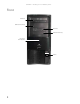
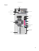
CHAPTER 1: Checking Out Your Gateway Server Front DVD/CD drive Additional 5.25-inch drive bay Diskette drive Additional 3.
www.gateway.
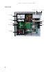
CHAPTER 1: Checking Out Your Gateway Server Interior Power supply module Cover release latch 5.25-inch drive bays 3.5-inch drive bays Front fan Processor air duct Internal 3.
www.gateway.
CHAPTER 1: Checking Out Your Gateway Server 6
CHAPTER2 Setting Up Your Server • • • • • • Setting up the hardware Protecting from power source problems Starting your server Turning off your server Setting up the operating system Initial hardware settings 7
CHAPTER 2: Setting Up Your Server Setting up the hardware To make sure that your working environment is safe: • Use a clean, dry, flat, stable surface for your server. Allow at least 6 inches at the back of the server for cabling and air circulation. • Use the instructions on your server’s setup poster to set up your hardware. Warning Your server comes with a 3-wire AC power cords fitted with the correct plug style for your region.
www.gateway.com To start the server: 1 Press the power button. Power button/power indicator LED When the power indicator LED is... It means... Blue The server is turned on. Off The server is turned off. Slowly blinking Low power state (S1 — S3) If nothing happens when you press the power button: • Make sure that the UPS, if you are using one, is connected securely to an electrical outlet, turned on, and working correctly.
CHAPTER 2: Setting Up Your Server Turning off your server Every time you turn off your server, first shut down the operating system. You may lose data if you do not follow the correct procedure. Warning The power button on the server does not turn off server AC power. To remove AC power from the server, you must unplug both AC power cords from the wall outlet or power source. The power cords are considered the disconnect device to the main (AC) power.
CHAPTER3 Maintaining Your Server • • • • Caring for your server Preparing for system recovery System administration Updating the baseboard management controller firmware • Using your Server Companion DVD 11
CHAPTER 3: Maintaining Your Server Caring for your server To extend the life of your server: • Be careful not to bump or drop your server. • When transporting your server, we recommend that you put it in the original packaging materials. • Keep your server and magnetic media away from equipment that generates magnetic fields. • Avoid subjecting your server to extreme temperatures. Do not expose your server to heating ducts or other heat-generating objects.
www.gateway.com If your computer screen is a flat panel display, use only a damp, soft cloth to clean it. Never spray water directly onto the screen. - OR If your computer screen is not a flat panel display, use a soft cloth dampened with glass cleaner to clean the screen. Never spray cleaner directly onto the screen. Cleaning the tape drive If you use a tape drive to back up your files, regular maintenance will lengthen the life of the drive.
CHAPTER 3: Maintaining Your Server Server security Using BIOS security passwords To prevent unauthorized use of the server, you can set server startup passwords. Set an administrator password to prevent unauthorized access to the BIOS Setup utility. To set the BIOS security passwords: 1 Restart your server, then press F2 when the Gateway logo screen appears during startup. The BIOS Setup utility opens. 2 3 4 5 Select the Security menu. Select Set Supervisor Password.
www.gateway.com Using your Server Companion DVD You can use your Server Companion DVD to: • Install hardware drivers • Install programs • View server documentation Server Companion DVD contents The Server Companion DVD is a tool you can use to help maintain your server. The DVD contains: • Computer and component documentation • Drivers and utilities for servers running Windows 2003 Server Viewing documents The DVD contains documents for your server and for some optional components.
CHAPTER 3: Maintaining Your Server To access the files manually: • Open the Drivers folder on the Server Companion DVD, then open the appropriate subfolder. To extract drivers and programs to diskettes: 1 Insert the Server Companion DVD into your server’s DVD drive. The Gateway Application and Driver Recovery window opens. - OR If the window does not open automatically, run the file Runmenu.exe on the DVD. 2 Click Extract Drivers.
CHAPTER4 Installing Components • • • • • • • • • • • • Preparing to install components Preventing static electricity discharge Accessing the internal components Installing drives Configuring your onboard RAID solution Installing memory Installing PCI expansion cards Replacing the processor Replacing a power supply module Replacing a fan Replacing the CMOS battery Replacing the system board 17
CHAPTER 4: Installing Components Important You must open your server case to install components. If you are not comfortable with these procedures, get help from a more experienced computer user or computer service technician, or contact Gateway Customer Care.
www.gateway.com • Remove components from their antistatic bags only when you are ready to use them. Do • not lay components on the outside of antistatic bags because only the inside of the bags provide electrostatic protection. Always hold expansion cards by their edges or their metal mounting brackets. Avoid touching the edge connectors and components on the cards. Never slide expansion cards or components over any surface.
CHAPTER 4: Installing Components 5 Swing the side panel away from the computer. 6 Lift the panel away from the server and place it out of the way. Removing the bezel assembly To remove the bezel assembly: 1 Follow the instructions in “Opening the server case” on page 19. 2 After removing the side panel, press the three black plastic tabs (positions indicated by the arrows) to release the right side of the bezel.
www.gateway.com Removing the processor air duct To remove the processor air duct: 1 Follow the instructions in “Preventing static electricity discharge” on page 18. 2 Follow the instructions in “Opening the server case” on page 19. 3 Remove the cables from the air duct cable clip. 4 Grasp the air duct handle and remove the processor air duct from the chassis.
CHAPTER 4: Installing Components Installing the processor air duct Important Be careful not to snag or unplug the fan cable when you install the processor air duct. To install the processor air duct: 1 Align the left side of the processor air duct with the front fan and insert the installation tabs on the bottom of the air duct into the installation holes in the side of the chassis. Processor air duct installation tabs Processor air duct installation holes 2 Press the processor air duct into place.
www.gateway.com Installing the bezel assembly Important If you have installed any new drives in the external drive bays, make sure to remove the corresponding filler panels in the bezel before installing it. To install the bezel assembly: 1 Insert the tabs on the left side of the bezel into the slots in the left side of the computer. 2 Swing the right side of the bezel in to insert the tabs on the right side of the bezel into the slots on the right side of the computer.
CHAPTER 4: Installing Components Closing the server case To close the server case: 1 Make sure that all of the internal cables are arranged inside the case so they will not be pinched when you close the case. 2 Align the panel tabs into the bottom case notches, then swing the side panel toward the top of the computer to secure it into place. 3 Replace the case cover thumbscrew. 4 Reconnect the power cords and all other cables.
www.gateway.com Installing drives Your server’s basic configuration includes one CD or DVD drive and one 3.5-inch diskette drive. Your server also has an additional 5.25-inch drive bay and 3.5-inch drive bay. Your server can have as many as four SATA (standard) or SCSI (optional) drives in three internal drive bays and one external fixed drive bay (the bottom 3.5-inch bay). CD or DVD drive 5.25-inch drive bay 3.5-inch floppy drive 3.
CHAPTER 4: Installing Components 3 If you are replacing a CD, DVD, or diskette drive, go to Step 6, otherwise follow the instructions in “Removing the bezel assembly” on page 20. 4 If you are adding a new drive to an available drive bay, remove the EMI shield from the bay by pulling the shield out of the bay. EMI shield 5 Slide the green drive retainer lever toward the back of the drive bay, then go to Step 8. 6 Disconnect the old drive’s cables from the back of the drive.
www.gateway.com Installing or replacing a hard drive Important To install a hard drive in the bottom external 3.5-inch drive bay, follow the instructions in “To install a drive in an external drive bay:” on page 25. Use these instructions to install or replace a hard drive. To install a hard drive in an internal drive bay: 1 Follow the instructions in “Preventing static electricity discharge” on page 18. 2 Follow the instructions in “Opening the server case” on page 19.
CHAPTER 4: Installing Components Configuring your onboard RAID solution Your server comes equipped with an onboard chipset for a SATA RAID solution, which supports RAID levels 0 (striping), 1 (mirroring), 5 (distributed data and parity), and 10 (RAID 0 + 1). You enable the onboard RAID solution in the BIOS (See “RAID Setup” on page 76) and configure RAID by launching the appropriate RAID BIOS console during the boot process.
www.gateway.com To launch the SATA RAID BIOS console: 1 Restart your server. 2 Press F2 when the Gateway logo screen appears during startup. The BIOS Setup utility opens. 3 From the Main BIOS menu, select the Advanced menu. 4 Select the Integrated Devices sub-menu. The Integrated Devices sub-menu opens.
CHAPTER 4: Installing Components 5 Select the NV RAID Configuration sub-menu. The NV RAID Configuration sub-menu opens. 6 7 8 9 For the NV RAID Configuration option, click Enabled. Select the SATA channels your hard drives are connected to and set them to Enabled. Exit the BIOS Setup utility. Restart your server. During the boot process you will see the following message: 10 Press F10. The RAID BIOS console opens. 11 Configure the RAID options, then exit the RAID BIOS console. 12 Reboot the server.
www.gateway.com To configure the SATA RAID solution: 1 Open the RAID BIOS console as described in the previous procedure. The Define a New Array screen opens. 2 Select a RAID Mode from the list at the top left of the screen.
CHAPTER 4: Installing Components 3 Select a Stripping Block size from the list at the top right of the screen. 4 Highlight the free disk you want to use from the list on the left side of the screen.
www.gateway.com 5 Press the right arrow key to move the disk to the Array Disks list on the right side of the screen. Do this for all disks you want to use in the array. 6 Press F7 to finish creating the array. When the confirmation box opens, press Y to clear the data on the disks.
CHAPTER 4: Installing Components The Array List opens showing the disks in the array. 7 To make the array bootable, press B (Set Boot) to change Boot No to Boot Yes. 8 Exit the RAID Configuration utility and reboot the server. Installing memory Caution Use only 667 Mhz compliant, 240-pin, SDRAM unbuffered ECC DIMM memory modules. The system board supports 4 DDR2 667 MHz vertical DIMMs to provide up to 8 GB of memory with ECC support.
www.gateway.com To install or replace memory: 1 Follow the instructions in “Preventing static electricity discharge” on page 18. 2 Follow the instructions in “Opening the server case” on page 19. 3 Pull the plastic tabs (1) away from the sides of the memory module slot. If you are replacing a memory module, lift the old memory module (2) out of the slot. 4 Align the notch on the new module with the notch in the memory module slot and press the module firmly into the slot.
CHAPTER 4: Installing Components PCI slot 1 PCI slot 2 PCI slot 3 PCI slot 4 PCI slot 5 To replace, add, or reseat a PCI expansion card: Follow the instructions in “Preventing static electricity discharge” on page 18. 1 2 3 4 Follow the instructions in “Opening the server case” on page 19. If you are replacing a card, disconnect any cables that are attached to the old card. Loosen the captive thumbscrew on the card retention bar and swing the bar out from the back of the chassis.
www.gateway.com 6 Press the new card into the expansion slot. To help insert the card you can slightly rock the card end-to-end, but do not bend the card sideways. 7 Swing the card retention bar back into place and tighten the captive thumbscrew. Card retention bar.
CHAPTER 4: Installing Components 8 Connect any cables to the card. For more information, see the instructions in the card’s documentation. 9 Follow the instructions in “Closing the server case” on page 24. 10 See the card’s documentation for software installation instructions. Replacing the processor Warning The processors and heatsink may be hot if the computer has been running. Also, there may be sharp edges on the heatsink. Consider wearing protective gloves.
www.gateway.com 5 Unlock the retention lever and lift it up to release the processor. 6 Lift the processor out of the socket and place it in a static-free bag or case for storage. 7 Insert the new processor into the socket, making sure that the gold triangle on the corner is situated as shown in the following illustration. Caution The processor only fits the socket when oriented as indicated. Do not force the processor into the socket to avoid bending the pins or damaging the processor.
CHAPTER 4: Installing Components 8 When the processor is oriented correctly and in place, press it firmly into the socket, rotate the retention lever into place until it clicks. Caution The heatsink has Thermal Interface Material (TIM) located on the bottom of it. Use caution when you unpack the heat sink so you do not damage the TIM. If you are reusing the original heatsink, make sure that the TIM on the bottom of the heatsink is not damaged.
www.gateway.com 4 While pressing the green latch on the power supply module, grasp the handle and pull the module straight out from the server. 5 Slide the new power supply module into the empty power supply bay until the green latch snaps into place. 6 Plug the power cord into the new power supply module.
CHAPTER 4: Installing Components Replacing a fan Important Make sure that you replace a fan with an identical replacement fan. To replace a front fan: 1 Follow the instructions in “Preventing static electricity discharge” on page 18. 2 Follow the instructions in “Opening the server case” on page 19. 3 Remove the processor air duct by following the instructions in “Removing the processor air duct” on page 21. 4 Unplug the fan cable from the fan connector on the system board.
www.gateway.com To replace a back fan: 1 Follow the instructions in “Preventing static electricity discharge” on page 18. 2 Follow the instructions in “Opening the server case” on page 19. 3 Unplug the fan cable from the fan connector on the system board. Fan cable Fan retention screw Fan retention screw 4 Unscrew the four fan retention screws holding the fan to the back of the chassis. 5 Pull the fan from the chassis, noting the orientation.
CHAPTER 4: Installing Components 3 Record the BIOS settings on your printout, then close the utility. 4 Turn off your server, then follow the instructions in “Preventing static electricity discharge” on page 18. 5 Follow the instructions in “Opening the server case” on page 19. 6 Locate the old battery on the system board and note its orientation (see “System board” on page 5 for the general location of the battery). You will need to install the new battery the same way.
www.gateway.com 8 Remove the seven screws securing the system board to the case. Screw Screw Screw Screw Screw Screw Screw 9 Pull the system board away from the case and carefully remove it, then place it in a static-free bag on a stable work surface. 10 Insert the new system board into the case, aligning the holes in the board with the threaded standoffs on the side of the case. 11 Secure the system board to the case with the seven (7) screws you removed previously.
CHAPTER 4: Installing Components 46
CHAPTER5 Using the BIOS Setup Utility • • • • • Opening the BIOS Setup utility Updating the BIOS Recovering the BIOS Resetting BIOS passwords Updating or recovering the BMC 47
CHAPTER 5: Using the BIOS Setup Utility Opening the BIOS Setup utility The BIOS Setup utility stores basic settings for your server. These settings include basic hardware configuration, resource settings, and password security. These settings are stored and saved even when the power is off. Caution The options in the BIOS Setup utility have been set at the factory for optimal performance. Changes to these settings will affect the performance of your server.
www.gateway.com Recovering the BIOS If you encounter a problem while you are updating the BIOS, such as a power outage, the BIOS update may not be successful. If the system continues to try to boot from the new, corrupted BIOS, you can manually recover the old BIOS so you can try another update. Important This method does not work if the keyboard is connected through the KVM switch. To create a recovery disk: 1 Download 646MS100.
CHAPTER 5: Using the BIOS Setup Utility Resetting BIOS passwords To reset BIOS passwords, you must either reset and clear all BIOS settings, or use the Clear Password jumper. To reset all BIOS settings, follow the instructions in “Resetting BIOS passwords” on page 50. To clear the BIOS password(s): 1 Follow the instructions in “Preventing static electricity discharge” on page 18. Make sure that you turn off the server, then unplug the power cord(s) and all other cables connected to the server.
CHAPTER6 Troubleshooting • • • • • Telephone support Tutoring and training Safety guidelines Error messages Troubleshooting 51
CHAPTER 6: Troubleshooting Telephone support Before calling Gateway Customer Care If you have a technical problem with your server, follow these recommendations before contacting Gateway Customer Care: • Make sure that your server is connected correctly to a grounded AC outlet that is supplying power. • If a peripheral device, such as a keyboard or mouse, does not appear to work, make sure that all cables are plugged in securely and plugged into the correct port or jack.
www.gateway.com Tutoring and training Gateway's Customer Care professionals cannot provide hardware and software training. Instead, Gateway recommends the following training resources. Resource Service description For more information Gateway Learning Libraries A variety of courses and tutorials are available on CD. Select from several easy-to-use learning libraries. www.gateway.
CHAPTER 6: Troubleshooting Drive Not Ready The BIOS was unable to access the drive because it indicated it was not ready for data transfer. This is often reported by drives when no media is present. A: Drive Error The BIOS attempted to configure the A: drive during POST, but was unable to correctly configure the device. This may be due to a bad cable or faulty diskette drive. Insert BOOT diskette in A: The BIOS attempted to boot from the A: drive, but could not find a correct boot diskette.
www.gateway.com S.M.A.R.T. Capable but Command Failed The BIOS tried to send a S.M.A.R.T. message to a hard disk, but the command transaction failed. This message can be reported by an ATAPI device using the S.M.A.R.T. error reporting standard. S.M.A.R.T. failure messages may indicate the need to replace the hard disk. S.M.A.R.T. Command Failed The BIOS tried to send a S.M.A.R.T. message to a hard disk, but the command transaction failed. This message can be reported by an ATAPI device using the S.M.A.R.T.
CHAPTER 6: Troubleshooting PCI I/O conflict A PCI adapter generated an I/O resource conflict when configured by BIOS POST. PCI ROM conflict A PCI adapter generated an I/O resource conflict when configured by BIOS POST. PCI IRQ conflict A PCI adapter generated an I/O resource conflict when configured by BIOS POST. PCI IRQ routing table error BIOS POST (DIM code) found a PCI device in the system but was unable to figure out how to route an IRQ to the device.
www.gateway.com Troubleshooting First steps Warning To avoid bodily injury, do not attempt to troubleshoot your server problem if: - The power cords or plugs are damaged - Liquid has been spilled into your server - Your server was dropped - The case was damaged Instead, unplug your server and contact a qualified computer technician.
CHAPTER 6: Troubleshooting Beep codes Whenever a recoverable error occurs during the power-on self-test (POST), the BIOS displays an error message that describes the problem. The BIOS also sounds a beep code (one long tone followed by two short tones) during POST if the video configuration fails (a faulty video controller) or if an expansion card is not functioning correctly. One short beep indicates the BIOS will boot the operating system. No error found.
www.gateway.
CHAPTER 6: Troubleshooting BIOS The settings in the BIOS Setup utility are not retained • Replace the CMOS battery. For instructions, see “Replacing the CMOS battery” on page 43. Optical drive Your server does not recognize an optical drive • Restart your server, then open the BIOS Setup utility by pressing and holding F2 while your server restarts. Make sure that the IDE controllers are enabled. For more information, see “Using the BIOS Setup Utility” on page 47. • Reinstall the device driver.
www.gateway.com You are having problems with a SATA drive • For normal SATA drives (not SATA RAID), check the BIOS setup utility to see if the BIOS has recognized the drive. • Make sure that the power cable and SATA cables are attached securely to the drive cage. • If the drive is not detected, try a different SATA port. • Try swapping SATA cables between drives to determine if the cable is defective. • Try listening to the drive to determine if the drive is spinning up. If not, the drive may be defective.
CHAPTER 6: Troubleshooting The color is not uniform Make sure that the monitor warms up for at least 30 minutes before making a final judgment about color uniformity. Make sure that: • The monitor is not positioned too close to another monitor, electric fan, or fluorescent light. • You demagnetize the screen using the monitor’s degauss feature. For more information on degauss, see the monitor’s documentation.
APPENDIXA Server Specifications 63
APPENDIX A: Server Specifications The following specifications are for the standard configuration. Your server may contain optional equipment. All specifications are subject to change. System specifications Case size Tower (with standard power supply): 8 × 16.5 × 19.8 inches (203.2 × 419.2 × 502.7 cm) Tower (with redundant power supplies) 8 × 16.5 × 22.2 inches (203.2 × 419.2 × 563 cm) Weight Approximately 32 lbs (14.
www.gateway.com PCI device/slot PCI slots: ■ Slot 1 ■ Slot 2 ■ Slot 3 ■ Slot 4 ■ Slot 5 - Video Integrated Matrox G200 Graphics Core with 2.25 MB Up to 1280 × 1024, 8 bpp or 1024 × 768, 16 bpp RAID Six Serial ATA 2.0 ports from the MCP55 supporting entry level RAID functionality, including RAID levels 0, 1, 5, and 10.
APPENDIX A: Server Specifications Electronic specifications Memory map Address Range (hex) Amount Function 0 to 07FFFFh 640 KB DOS region, base system memory 0A0000h to 0BFFFFh 128 KB Video or SMM memory 0C0000h and 0DFFFFh 128 KB Expansion card BIOS and buffer area 0E0000h to 0FFFFFh 128 KB System BIOS 0E0000h to 0EFFFFh 2 MB Extended system BIOS FC000000h to FFFFFFFFh 64 MB PCI memory space Interrupts The following table reflects a typical configuration, but you can change these inte
www.gateway.com Interrupt Description IRQ14 Primary ATA, legacy mode PIRQA USB 1.1 controller 1 and 4 PIRQB Video PIRQC USB 1.1 controller 3, Native IDE, SATA PIRQD USB 1.1 controller 2 PIRQE Option for SCI, TCO, HPET #0,1,2 PIRQF Option for SCI, TCO, HPET #0,1,2 PIRQG Option for SCI, TCO, HPET #0,1,2 PIRQH USB 2.
APPENDIX A: Server Specifications 68
APPENDIXB BIOS Settings 69
APPENDIX B: BIOS Settings If you ever need to restore your BIOS settings, such as after a system board change, a record of the settings will make the process much easier. You can print this appendix, then record your custom BIOS settings on the printout. Only settings which can be changed are listed. For a complete list of viewable BIOS settings, run the BIOS Setup utility. To view all BIOS settings: 1 Restart your server 2 Press F2 when the Gateway logo screen appears during startup.
www.gateway.
APPENDIX B: BIOS Settings BIOS menu BIOS submenu Setting Value Serial-ATA 2 Primary Channel (auto-detected) Selects IDE Configuration sub-menu. Serial-ATA 2 Secondary Channel (auto-detected) Selects IDE Configuration sub-menu. Hard Disk Write Protect Disabled Enabled IDE Detect Time Out (Sec) 0, 5, 10, 15, 20, 25, 30, 35 ATA(PI) 80Pin Cable Detection Host & Device Host Device Onboard Floppy Controller Disabled Enabled Floppy A Disabled 1.44 MB 3½” 2.
www.gateway.
APPENDIX B: BIOS Settings BIOS menu BIOS submenu Setting Value 1st Drive Varies (Specifies boot sequence from the available devices.) nth Drive Varies (Specifies boot sequence from the available devices.) 1st Drive Varies (Specifies boot sequence from the available devices.) nth Drive Varies (Specifies boot sequence from the available devices.) 1st Drive Varies (Specifies boot sequence from the available devices.) nth Drive Varies (Specifies boot sequence from the available devices.
www.gateway.
APPENDIX B: BIOS Settings BIOS submenu BIOS 2nd level submenu Setting Value RAID Setup nVidia RAID Function Enabled Disabled SATA 0 Primary Channel Enabled Disabled SATA 0 Secondary Channel Enabled Disabled SATA 1 Primary Channel Enabled Disabled SATA 1 Secondary Channel Enabled Disabled SATA 2 Primary Channel Enabled Disabled SATA 2 Secondary Channel Enabled Disabled BIOS 2nd level submenu Setting Value Primary IDE Master (All IDE drives) (Below is shown information and options appr
www.gateway.com BIOS submenu BIOS submenu BIOS 2nd level submenu BIOS 2nd level submenu Setting Value PIO Mode Auto 0 1 2 3 4 DMA Mode Auto SWDMA 0-2 MWDMA 0-2 UWDMA 0-6 S.M.A.R.T. Auto Disabled Enabled 32Bit Data Transfer Disabled Enabled Setting Value USB Mass Storage Reset Delay 10 Sec 20 Sec 30 Sec 40 Sec Device #1 Only displayed if a device is detected. Includes a DeviceID string returned by the USB device.
APPENDIX B: BIOS Settings 78
APPENDIXC Legal Information 79
APPENDIX C: Legal Information Important safety information Warning Always follow these instructions to help guard against personal injury and damage to your Gateway system. Your Gateway system is designed and tested to meet the latest standards for safety of information technology equipment. However, to ensure safe use of this product, it is important that the safety instructions marked on the product and in the documentation are followed.
www.gateway.com Regulatory compliance statements United States of America Federal Communications Commission (FCC) Unintentional emitter per FCC Part 15 FCC Part 15 Class B Statement This device has been tested and found to comply with the limits for a Class B digital device, pursuant to Part 15 of the FCC rules. These limits are designed to provide reasonable protection against harmful interference in a residential installation.
APPENDIX C: Legal Information Caution Changes or modifications not expressly approved by Gateway could void the FCC compliance and negate your authority to operate the product. UL Warning Before removing or installing the chassis cover, make sure that the system power is not turned on or connected to AC power.
www.gateway.com Environmental information The product you have purchased contains extracted natural resources that have been used in the manufacturing process. This product may contain substances known to be hazardous to the environment or to human health. To prevent releases of harmful substances into the environment and to maximize the use of our natural resources, Gateway provides the following information on how you can responsibly recycle or reuse most of the materials in your “end of life” product.
APPENDIX C: Legal Information 84
Index Numerics 5.
Contents location 2, 3 I IDE cables 25 drive configuration 25 indicators 2 LED 9 information LED 59 installing 5.
www.gateway.
www.gateway.
8512069-Back.