E-9425R Server USERGUIDE ®
Contents Chapter 1: Checking Out Your Gateway Server . . . . . . . . . . . . . . . . . . . . . . . 1 Front . . . . . . . . . . . . . . . . . . . . . . . . . . . . . . . . . . . . . . . . . . . . . . . . . . . . . . . . . . . . . . Control panel . . . . . . . . . . . . . . . . . . . . . . . . . . . . . . . . . . . . . . . . . . . . . . . . . Back . . . . . . . . . . . . . . . . . . . . . . . . . . . . . . . . . . . . . . . . . . . . . . . . . . . . . . . . . . . . . . Interior . . . . . . . . . . . . . . . .
Contents Getting Help . . . . . . . . . . . . . . . . . . . . . . . . . . . . . . . . . . . . . . . . . . . . . . . . . Preventing static electricity discharge . . . . . . . . . . . . . . . . . . . . . . . . . . . . . . . . . . Opening the server case . . . . . . . . . . . . . . . . . . . . . . . . . . . . . . . . . . . . . . . . . . . . . Closing the server case . . . . . . . . . . . . . . . . . . . . . . . . . . . . . . . . . . . . . . . . . . . . . . Installing and removing drives . . . . . . . . . . .
www.gateway.com Beep codes . . . . . . . . . . . . . . . . . . . . . . . . . . . . . . . . . . . . . . . . . . . . . . . . . LED information . . . . . . . . . . . . . . . . . . . . . . . . . . . . . . . . . . . . . . . . . . . . . . Diagnostic LEDs . . . . . . . . . . . . . . . . . . . . . . . . . . . . . . . . . . . . . . . . . . . . . . BIOS . . . . . . . . . . . . . . . . . . . . . . . . . . . . . . . . . . . . . . . . . . . . . . . . . . . . . . . Optical drive . . . . . . . . . . . . . . . . . . . . .
Contents iv
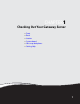
CHAPTER1 Checking Out Your Gateway Server • • • • • • Front Back Interior System board Hot-swap backplanes Getting Help 1
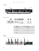
CHAPTER 1: Checking Out Your Gateway Server Front Control panel Optical drive SMIL module port Hard drives Control panel # Feature # Feature 1 2 USB ports 6 NIC status LED 2 Power button 7 System fault LED 3 ID button 8 Reset button 4 Power LED 9 NMI button 5 ID LED Back Dual NIC connectors PS/2 keyboard connector Server management port 2 PS/2 mouse connector VGA connector ID LED Dual USB connectors Serial port SAS JBOD connector (optional AC power connector
www.gateway.
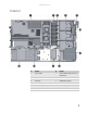
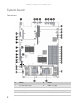
CHAPTER 1: Checking Out Your Gateway Server System board Connectors 37 36 35 34 33 32 31 30 29 28 4 # Feature # Feature 1 Rear dual USB Port (J35) 20 DIMM7 socket (J24) 2 Serial port (J31) 21 DIMM8 socket (J25) 3 ID LED (CR16) 22 Fan power/fan tach connector (J99) 4 VGA port (J39) 23 Processor 1 (CPU1) socket
www.gateway.
CHAPTER 1: Checking Out Your Gateway Server 6
www.gateway.
CHAPTER 1: Checking Out Your Gateway Server Getting Help In addition to your operating system’s documentation, you can use the following information resources to help you use your server. Server Companion DVD Use the Server Companion DVD to access file utilities, Windows Server 2003 drivers, and documentation for your server and its components. For instructions, see Using Your Server Companion DVD. Gateway Web site Gateway provides a variety of information on its Web site to help you use your server.
CHAPTER2 Setting Up Your Server • • • • • • Setting up the hardware Protecting from power source problems Mounting your server into a cabinet Starting your server Setting up the operating system Initial hardware settings 9
CHAPTER 2: Setting Up Your Server Setting up the hardware To make sure that your working environment is safe: • Use a clean, dry, flat, stable surface for your server. Allow at least 6 inches at the back of the server for cabling and air circulation. • Use the instructions on your server’s setup poster to set up your hardware. Caution Your server comes with 3-wire AC power cords fitted with the correct plug style for your region.
www.gateway.com Some surge protectors and uninterruptible power supplies include simple line-conditioning capabilities. Uninterruptible power supplies Use an uninterruptible power supply (UPS) to protect your server from data loss during a total power failure. A UPS uses a battery to keep your server running temporarily during a power failure and lets you save your work and shut down your server. You cannot run your server for an extended period of time while using only the UPS.
CHAPTER 2: Setting Up Your Server 3 Align the slots in the back server rails with the studs on the side of the server, then engage the slots with the studs and slide the rail forward until it stops. Locking screw (installed) Stud Back server rail (installed) Stud 4 Align the locking screw holes in the rails with the threaded screw holes in the server, then install one locking screw through the each back server rail.
www.gateway.com 6 Attach one mounting nut to each of the two back cabinet posts where you plan to install the server. Hinged back rail mounting bracket Back cabinet post Mounting nut 7 Hold the server in place in the cabinet and swing the hinged back rail mounting brackets into alignment with the mounting nuts, then secure the back in place with two mounting screws (one on each side).
CHAPTER 2: Setting Up Your Server Warning You must support the server while installing or removing the front and back mounting screws. If the server is not supported, damage to the server or injury may result. 8 Align the mounting screw holes in the server handles with the front mounting nuts, then secure the front in place with two mounting screws (one on each side).
www.gateway.com 3 Remove the bezel lock keys from the inside of the bezel, then insert the left side of the bezel into the left handle and swing the right side of the bezel in until it snaps into place. 4 When the bezel is in place, lock the bezel by inserting the key into the lock in the lower right corner of the bezel and turning it clockwise until it stops. 5 Put the key in a safe place.
CHAPTER 2: Setting Up Your Server Starting your server Before you start your server for the first time: • Make sure that the server and monitor are plugged into a power outlet or surge protector and that the surge protector (if you are using one) is turned on. Caution When you connect peripheral devices to the server, make sure that your server and devices are turned off and the power cords are unplugged.
www.gateway.com Turning off your server Every time you turn off your server, first shut down the operating system. You may lose data if you do not follow the correct procedure. To turn off the server: Caution The power button on the server does not turn off server AC power. To remove AC power from the server, you must unplug the AC power cords from the wall outlet or power source. The power cords are considered the disconnect device to the main (AC) power.
CHAPTER 2: Setting Up Your Server 18
CHAPTER3 Maintaining Your Server • • • • • Caring for your server Preparing for system recovery System administration Identifying your server Updating the baseboard management controller firmware • Using your Server Companion DVD 19
CHAPTER 3: Maintaining Your Server Caring for your server To extend the life of your server: • Be careful not to bump or drop your server. • When transporting your server, we recommend that you put it in the original packaging materials. • Keep your server and magnetic media away from equipment that generates magnetic fields, such as unshielded speakers. • Avoid subjecting your server to extreme temperatures. Do not expose your server to heating ducts or other heat-generating objects.
www.gateway.com Cleaning the screen Caution The computer screen is made of specially coated glass and can be scratched or damaged by abrasive or ammonia-based glass cleaners. If your computer screen is an LCD monitor, use only a damp, soft cloth to clean it. Never spray water directly onto the screen. - OR If your computer screen is not a flat panel display, use a soft cloth dampened with glass cleaner to clean the screen. Never spray cleaner directly onto the screen.
CHAPTER 3: Maintaining Your Server Server security Locking the server To lock the server: 1 Remove the bezel lock keys from the inside of the bezel, then snap on the bezel. The handles must be installed for the bezel to snap on. For instructions, see “Installing the bezel” on page 14. 2 Insert the key into the lock and rotate it ¼ turn clockwise. To unlock it, rotate the key ¼ turn counter-clockwise.
www.gateway.
CHAPTER 3: Maintaining Your Server To install Acrobat Reader 7: • Click the link for Acrobat on the Documentation page. - OR Run Docs\Reader\app21279\Setup.exe from the Server Companion DVD. Installing drivers and programs You can install drivers and programs directly onto the server by using the Server Companion DVD. You can also extract drivers onto diskette from the DVD at any Windows workstation.
www.gateway.com 3 Press any key to boot from the DVD. The Gateway Options Main Menu appears. 4 Follow any on-screen instructions. You can use the options in this menu to reformat your hard drive, create mass-storage driver disks, or reload Windows and selected applications.
CHAPTER 3: Maintaining Your Server 26
CHAPTER4 Installing Components • • • • • • • • • • • • • Preparing to install components Preventing static electricity discharge Opening the server case Closing the server case Installing and removing drives Installing memory Installing and removing PCI expansion cards Replacing system fans Replacing or adding a processor Replacing a power supply module Replacing the hot-swap backplanes Replacing the hot-swap backplanes Replacing the ROMB battery pack for the mezzanine RAID card • Replacing the CMOS batter
CHAPTER 4: Installing Components Preparing to install components Selecting a place to work Work on your server in an area that: • Is clean (avoid dusty areas). • Is a low-static environment (avoid carpeted areas). • Has a stable surface on which to set your server. • Has enough room to place all of your server parts. • Is near a grounded outlet so you can test your server after installation. • Is near a telephone (in case you need help from Gateway Customer Care).
www.gateway.com • Avoid static-causing surfaces such as carpeted floors, plastic, and packing foam. • Avoid working on the server when your work area is extremely humid. • Remove components from their antistatic bags only when you are ready to use them. Do • not lay components on the outside of antistatic bags because only the inside of the bags provide electrostatic protection. Always hold expansion cards by their edges or their metal mounting brackets.
CHAPTER 4: Installing Components 7 Press down the two blue retaining clips (1) on the sides of the top front cover, then slide the top front cover back (2) and lift it off the server. Caution For correct cooling and air flow, always reinstall the top covers before you turn on the server. Operating the server without the covers in place will cause the server to overheat.
www.gateway.com 4 Replace the screw (2) to hold the rear top cover in place. 5 Reconnect the power cord(s) and all other cables. Installing and removing drives Your server’s basic configuration includes one optical drive and as many as four SATA or SAS hot-swap hard drives. An optional diskette drive can also be added in place of the hard drive on the left side of the server. As you prepare to install drives, remember: • You must install the optional diskette drive in the left converted hard drive bay.
CHAPTER 4: Installing Components 5 Loosen the thumbscrew (1) holding the retaining clip (2) against the side of the optical drive, then move the retaining clip away from the drive. Important The hard drive carriers shown in these illustrations may look different than the actual hard drive carriers in your server. 6 Push the optical drive to the right to release the drive from the drive bay, then pull the drive out of the bay.
www.gateway.com 9 Slide the new optical drive into the drive bay, making sure you align the drive with the retaining clips on both sides of the drive. 10 Push the retaining clip against the drive until snug, then tighten the thumbscrew to hold the drive in place. 11 12 13 14 Connect the 44-pin optical drive cable to the back of the optical drive interface board. Follow the instructions in “Closing the server case” on page 30.
CHAPTER 4: Installing Components 3 Pull the drive carrier straight out of the server. 4 If you are replacing a hard drive, remove the four screws from the bottom of the drive tray that secure the old hard drive to the tray, then remove the drive from the tray. 5 Using the four screws you removed, install the new hard drive into the drive tray. 6 Make sure that the tray’s release lever is open, then slide the new drive fully into the empty hot-swap drive bay.
www.gateway.com Thumbscrew Diskette drive/adapter assembly (inserted) 8 Follow the instructions in “Closing the server case” on page 30. 9 Reinstall the bezel, if required, by snapping it into place on the front of the chassis. 10 Reconnect all power cords and peripheral device cables, then turn on the server. Filling empty drive bays Empty drive bays in the server must be filled by empty drive trays.
CHAPTER 4: Installing Components Installing memory Caution Use only 667 MHz Fully-Buffered (FB-DIMM) memory modules. Your server supports eight 667 MHz fully-buffered DIMMs (FB-DIMMs) to provide up to a maximum of 32 GB with fully-buffered support. Supported DIMM sizes include 512 MB, 1 GB, 2 GB, and 4 GB. DIMMs must be low-profile or ultra low-profile and cannot exceed 1.2” in height.
www.gateway.
CHAPTER 4: Installing Components Sparing mode For the sparing mode, please follow the online spare FBDIMM configuration requirements (in addition to general configuration requirements) below: • When only DIMM1 and DIMM3 are being used, they must be fully populated with dual-rank FBDIMMs. • If DIMM1 and DIMM3, and DIMM2 and DIMM4 are being used, they must be fully populated. • If installed, DIMM1 and DIMM3, and DIMM2 and DIMM4 must contain FBDIMMs with identical part numbers.
www.gateway.com Installing and removing PCI expansion cards Caution Always operate your server with the PCI riser assembly in place. The PCI riser assembly is important for correct airflow within the server. Operating the server without the PCI riser assembly in place could result in overheating and possible data loss or equipment damage. The system board provides one 280-pin PCI-X/PCI-E x8 expansion slot and one PCI-E x8 expansion slot.
CHAPTER 4: Installing Components 5 Place the PCI riser assembly on a stable, static-free surface, then loosen the screw (3) holding the card lock in place. 6 Open the card lock (4), then pull out the PCI card (5). If you are not replacing the PCI card, insert the slot cover into the back of the riser card assembly. 7 If you are replacing the riser card, continue with the next step. - OR If you are replacing the PCI card, go to Step 10.
www.gateway.com 10 Insert the new PCI card into the riser card, making sure any connectors extend through the slot at the back of the assembly and that the card is fully seated in the riser card. 11 Close the lock to hold the card in place, then replace the screw that holds the lock closed. 12 Position the PCI riser assembly over the PCI sockets on the server board, Then press the PCI riser assembly into the PCI sockets. 13 Follow the instructions in “Closing the server case” on page 30.
CHAPTER 4: Installing Components 6 Insert the replacement fan group into the fan cage. 7 Connect the 6-pin fan tach cable from the fan to the fan board. 8 Follow the instructions in “Closing the server case” on page 30. To replace the system fans and the fan board: 1 Follow the instructions in “Preventing static electricity discharge” on page 28. Make sure that you turn off the server, then unplug the power cord(s) and all other cables connected to the server.
www.gateway.com Important Make sure that the arrows on top of the fans indicating airflow point to the back of the chassis. The fan cable should exit the fan module toward the back of the chassis. 10 Connect the 6-pin fan tach cables from the fans to the fan tach connectors on the fan board. 11 Follow the instructions in “Closing the server case” on page 30. Replacing or adding a processor Warning Processors and heat sinks may be hot if the computer has been running.
CHAPTER 4: Installing Components 4 Push down, then pull out and up on the two heat sink retention levers (1) and move them out of the way. Caution The heat sink has Thermal Interface Material (TIM) on the bottom. Be careful not to damage this material when you remove the heat sink from the processor. If removing the heat sink also pulls the processor out of the processor socket, the processor could be damaged. 5 Remove the heat sink from the processor.
www.gateway.com Caution The processor only fits the socket when oriented as indicated. Do not force the processor into the socket to avoid bending the pins or damaging the processor. If the processor does not fit completely, check its orientation and check for bent pins. 8 Insert the new processor into the socket, making sure that the gold triangle on the corner is situated as shown in the following illustration.
CHAPTER 4: Installing Components 11 Push down the heat sink retaining levers (3) and lock them under the retaining hooks on the heat sink socket. 12 Follow the instructions in “Closing the server case” on page 30. Replacing a power supply module Caution The power supplies in this server contain no user-serviceable parts. Only a qualified computer technician should service the power supplies. Your server comes with 3-wire AC power cords fitted with the correct plug style for your region.
www.gateway.com 3 Press the retaining clip on the power supply to the left to release the power supply module from the chassis. 4 Pull the power supply module straight out of the server with the handle. It may take considerable force to remove. 5 Insert the new power supply module into the server, with the retaining clip on the right, until it locks into place. 6 Reconnect the AC power cord for the new power supply module.
CHAPTER 4: Installing Components 7 Align the new power distribution board with the stand-off and locking tabs on the chassis, then place it on the stand-offs and slide it toward the side of the chassis until the tab clicks into place. 8 Replace the screw you previously removed. 9 Reconnect the power cables. See “System board” on page 4 for the location of the connectors on the system board.
www.gateway.com 6 Slide the power cage (4) toward the front of the chassis to disengage the locking tabs, then lift the power cage out of the chassis. 7 Place the new power cage into the chassis, aligning the cage with the locking tabs in the chassis, then slide the power cage toward the back of the chassis to engage the locking tabs. 8 Replace the screws you previously removed. 9 Replace the power distribution board by following the instructions in “Replacing the hot-swap backplanes” on page 49.
CHAPTER 4: Installing Components Caution Pressing or pulling on any components on the backplane could result in damage to the backplane. Caution Make sure that you do not pinch, bind, or damage any cables as you install the backplane. 8 Holding the new backplane by the edges only, align it with the locking tabs on the chassis, then place it on the locking tabs and slide it to the left until it stops. 9 Tighten the thumbscrew to secure the backplane. 10 Reconnect all cables to the backplane.
www.gateway.com 3 Press the release handle (1), then slide the ROMB battery pack for the mezzanine RAID card (2) toward the back of the chassis to release it from the locking tabs and lift it out of the chassis (3). 4 Align the holes in the bottom of the new ROMB battery pack for the mezzanine RAID card (1) with the locking tabs in the chassis, then press it into place in the chassis. 5 Slide the ROMB battery pack for the mezzanine RAID card (2) toward the front of the chassis until it clicks into place.
CHAPTER 4: Installing Components 4 Align the holes on one side of the board with the plastic standoffs (1) and align the other side with the mezzanine board slot. 5 Push down on the board (2) to seat it in the mezzanine board slot and onto the plastic standoffs until the retaining tabs snap into place. 6 Replace the PCI riser card assembly by following the instructions in “Installing and removing PCI expansion cards” on page 39. 7 Follow the instructions in “Closing the server case” on page 30.
www.gateway.com Replacing the CMOS battery Warning Danger of explosion if battery is incorrectly replaced. Replace only with the same or equivalent type recommended by the manufacturer. Dispose of or recycle used batteries by taking them to a hazardous waste facility. Follow all local regulations for correct battery disposal. If the server clock does not keep time or the settings in the BIOS Setup utility are not saved when you turn off the server, replace the CMOS battery with an equivalent battery.
CHAPTER 4: Installing Components Replacing the control panel Caution Your server must be operated with a control panel module in place. To replace the control panel: 1 Follow the instructions in “Preventing static electricity discharge” on page 28. Make sure that you turn off the server, then unplug the power cord(s) and all other cables connected to the server. 2 Follow the instructions in “Opening the server case” on page 29.
www.gateway.com 6 Remove the heat sinks and processors by following the instructions in “Replacing or adding a processor” on page 43. 7 Disconnect all cables from the system board, noting their locations and orientation. (You will reconnect the cables after you install the new board.) 8 Loosen the two thumbscrews (1) that secure the system board to the server.
CHAPTER 4: Installing Components 16 Reinstall the PCI riser assembly by following the instructions in “Installing and removing PCI expansion cards” on page 39. 17 Reinstall the system fans and fan cage by following the instructions in “Replacing system fans” on page 41. 18 Follow the instructions in “Closing the server case” on page 30. 19 Turn on your server, then press F2 when the Gateway logo screen appears during startup. The BIOS Setup utility opens.
CHAPTER5 Using the BIOS Setup Utility • • • • • Opening the BIOS Setup utility Updating the BIOS Recovering the BIOS Resetting the BIOS Updating and recovering the BMC 57
CHAPTER 5: Using the BIOS Setup Utility Opening the BIOS Setup utility The BIOS Setup utility stores basic settings for your server. These settings include basic hardware configuration, resource settings, and password security. These settings are stored and saved even when the power is off. Caution The options in the BIOS Setup utility have been set at the factory for optimal performance. Changes to these settings will affect the performance of your server.
www.gateway.com Recovering the BIOS If you encounter a problem while you are updating the BIOS, such as a power outage, the BIOS update may not be successful. If the system continues to try to boot from the new, corrupted BIOS, you can manually recover the old BIOS so you can try another update. Important This method does not work if the keyboard is connected through the KVM switch. To recover the old BIOS: 1 Insert a diskette, CD or DVD, or a bootable USB “disk-on-key” containing the AMIBOOT.ROM file.
CHAPTER 5: Using the BIOS Setup Utility 11 Place the jumper back onto pins 1-2. 12 Follow the instructions in “Closing the server case” on page 30. 13 Plug in the AC power cords and turn on the server, then verify that the recovery was successful. Resetting the BIOS You can use two methods to clear all BIOS Setup settings and return them to the factory defaults: • Press the power and reset buttons on the front of the server. • Move the Clear CMOS jumper on the system board.
www.gateway.com 8 Reconnect the power cords and turn on the server. The BIOS is reset. 9 Turn off the server, then disconnect the power cords and all other cables connected to the server. 10 Follow the instructions in “Opening the server case” on page 29. 11 Place the jumper back onto pins 1-2. 12 Follow the instructions in “Closing the server case” on page 30. Resetting BIOS passwords To reset BIOS passwords, you must either reset and clear all BIOS settings, or use the Clear Password jumper.
CHAPTER 5: Using the BIOS Setup Utility Updating and recovering the BMC Updating the BMC firmware To update the BMC firmware: 1 Download the BMC firmware zip file from support.gateway.com. 2 Read the release notes for the firmware update. 3 Follow the instructions on the Web site or in the readme.txt file in the downloaded zip file to update the firmware. 4 When the BMC update is complete, reboot your server.
www.gateway.com 8 Follow the instructions in “Closing the server case” on page 30. 9 Plug in the AC power cords and turn on the server for normal use.
CHAPTER 5: Using the BIOS Setup Utility 64
CHAPTER6 Troubleshooting • • • • • Telephone support Tutoring and training Safety guidelines Error messages Troubleshooting 65
CHAPTER 6: Troubleshooting Telephone support Before calling Gateway Customer Care If you have a technical problem with your server, follow these recommendations before contacting Gateway Customer Care: • Make sure that your server is connected correctly to a grounded AC outlet that is supplying power. • If a peripheral device, such as a keyboard or mouse, does not appear to work, make sure that all cables are plugged in securely and plugged into the correct port or jack.
www.gateway.com Tutoring and training Gateway's Customer Care professionals cannot provide hardware and software training. Instead, Gateway recommends the following training resources. Resource Service description For more information Gateway Learning Libraries A variety of courses and tutorials are available on CD. Select from several easy-to-use learning libraries. www.gateway.
CHAPTER 6: Troubleshooting Boot messages Boot Failure ... This is a generic message indicating the BIOS could not boot from a particular device. This message is usually followed by other information concerning the device. Invalid Boot Diskette A diskette was found in the drive, but it is not configured as a bootable diskette. Drive Not Ready The BIOS was unable to access the drive because it indicated it was not ready for data transfer. This is often reported by drives when no media is present.
www.gateway.com Secondary Master Drive - ATAPI Incompatible The IDE/ATAPI device configured as Secondary Master failed an ATAPI compatibility test. This message is typically displayed when the BIOS is trying to detect and configure IDE/ATAPI devices in POST. Secondary Slave Drive - ATAPI Incompatible The IDE/ATAPI device configured as Secondary Slave failed an ATAPI compatibility test. This message is typically displayed when the BIOS is trying to detect and configure IDE/ATAPI devices in POST. S.M.A.R.T.
CHAPTER 6: Troubleshooting NVRAM Ignored The NVRAM data used to store Plug’n’Play (PnP) data was not used for system configuration in POST. NVRAM Bad The NVRAM data used to store Plug’n’Play (PnP) data was not used for system configuration in POST due to a data error. Static Resource Conflict Two or more Static Devices are trying to use the same resource space (usually Memory or I/O). PCI I/O conflict A PCI adapter generated an I/O resource conflict when configured by BIOS POST.
www.gateway.com Miscellaneous messages Keyboard Error Keyboard is not present or the hardware is not responding when the keyboard controller is initialized. Keyboard/Interface Error Keyboard Controller failure. This may indicate a problem with system hardware. System Halted The system has been halted. A reset or power cycle is required to reboot the machine. This message appears after a fatal error has been detected.
CHAPTER 6: Troubleshooting • Remove the top panel by following the instructions in “Opening the server case” on • page 29, then make sure that all cables inside the case are attached securely. Also, make sure that the colored cable edges are aligned correctly and that the connectors do not miss any pins. If you have the correct test equipment, make sure that the new battery has power. Although unlikely, your new battery may be defective.
www.gateway.
CHAPTER 6: Troubleshooting Diagnostic LEDs This system board provides a set of eight diagnostic (Port 80) LEDs. If you are troubleshooting your system, these LEDs can help you determine where errors are taking place. If you are experiencing problems with your server, open the case and check these LEDs (CR8 to CR15) on the system board, then check the tables on the following pages to determine the problem.
www.gateway.com In determining the code, Off = 0 and On = 1. Based on this, you can determine the corresponding hex code. Then, by checking “POST code checkpoints” on page 75, “Bootblock initialization code checkpoints” on page 77, “Bootblock recovery code checkpoints” on page 78, “DIM code checkpoints” on page 79, and “ACPI runtime checkpoints” on page 79, you can find out where an error is taking place.
CHAPTER 6: Troubleshooting 76 Check point Description 30 Initialize System Management Interrupt. 2A Initialize different devices through DIM. See “DIM code checkpoints” on page 79 for more information. 2C Initialize different devices. Detects and initializes the video adapter installed in the system that has optional ROMs. 2E Initialize all the output devices. 31 Allocate memory for ADM module and uncompress it. Give control to ADM module for initialization.
www.gateway.com Check point Description A1 Clean-up work needed before booting to operating system. A2 Take care of runtime image preparation for different BIOS modules. Fill the free area in F000h segment with 0FFh. Initializes the Microsoft® IRQ Routing Table. Prepares the runtime language module. Disables the system configuration display, if needed. A4 Initialize runtime language module. A7 Display the system configuration screen, if enabled.
CHAPTER 6: Troubleshooting Check point Description D8 The Runtime module is uncompressed into memory. CPUID information is stored in memory. D9 Store the Uncompressed pointer for future use in PMM. Copying Main BIOS into memory. Leaves all RAM below 1 MB Read-Write, including E000 and F000 shadow areas, but closing SMRAM. DA Restore CPUID value back into register. Give control to BIOS POST (ExecutePOSTKernel). See “POST code checkpoints” on page 75 for more information.
www.gateway.com DIM code checkpoints The Device Initialization Manager (DIM) gets control at various times during BIOS POST to initialize different system buses. The following table describes the main checkpoints where the DIM module is accessed. Checkpoint Description 2A Initialize different buses and perform the following functions: ■ Reset, Detect, and Disable (function 0) — Disables all device nodes, PCI devices, and PnP ISA cards. It also assigns PCI bus numbers.
CHAPTER 6: Troubleshooting Optical drive Your server does not recognize an optical drive • Restart your server, then open the BIOS Setup utility by pressing and holding F2 while your server restarts. Make sure that the IDE controllers are enabled. For more information, see “Using the BIOS Setup Utility” on page 57. • Reinstall the device driver. For instructions, see Using Your Server Companion DVD.
www.gateway.com You are having problems with a SATA drive • For normal SATA drives (not SATA RAID), check the BIOS setup utility to see if the BIOS has recognized the drive. • Make sure that the power cable and SATA cables are attached securely to the drive cage. • If the drive is not detected, try a different SATA port. • Try swapping SATA cables between drives to determine if the cable is defective. • Try listening to the drive to determine if the drive is spinning up. If not, the drive may be defective.
CHAPTER 6: Troubleshooting Make sure that: • The monitor is not positioned too close to another monitor, electric fan, or fluorescent light. • You demagnetize the screen using the monitor’s degauss feature. For more information on degauss, see the monitor’s documentation. A horizontal line or wire is visible across the CRT monitor screen The monitor may use thin damper wires, located approximately 1/3 of the way from the upper and lower screen edges, to stabilize the internal aperture grille.
APPENDIXA Server Specifications • • • • • System specifications System board specifications Environmental specifications Electronic specifications Additional specifications 83
APPENDIX A: Server Specifications System specifications Case size (H×W×L) 1.70 × 15.79 × 29.58 inches (4.32 × 40.10 × 75.14 cm) Weight 25 to 37 lbs. (11.34 to 16.
www.gateway.com SATA 2 SFF 8087 connectors to support as many as 6 SATA devices. ACPI ACPI 2.0b compliance Supports: ■ S0 ■ S1 ■ S5 Environmental specifications The following specifications identify maximum environmental conditions. At no time should the server run under conditions which violate these specifications.
APPENDIX A: Server Specifications Interrupts Important If you disable an IDE controller to free the interrupt for that controller, you must physically unplug the IDE cable from the system board. Simply disabling the drive by configuring the BIOS option does not make the interrupt available. The following table reflects a typical configuration, but you can change these interrupts. Use this information to determine how to program each interrupt.
www.gateway.com Pin Signal Name 8 Power good 9 Stand by +5 V 10 +12 V 11 +12 V 12 +3.3 V 13 +3.
APPENDIX A: Server Specifications Pin Signal Name 3 Blue (analog color signal B) 4 No connection 5 GND 6 GND 7 +5 V 8 GND 9 +5 V 10 GND 11 No connection 12 SDA 13 HSYNC (horizontal sync) 14 VSYNC (vertical sync) 15 SCL Serial port connector Pin Signal Name Description 1 DCD Data Carrier Detect1 2 RXDATA Receive Data 3 TXDATA Transmit Data 4 DTR Data Terminal Ready 5 GND Ground 6 DSR Data Set Ready 7 RTS Request To Send 8 CTS Clear To Send 9 RI Ring I
www.gateway.com Pin Signal Name 5 Keyboard (or mouse) clock 6 NC External USB connectors Pin Signal Name 1 +5 V 2 USBN Data- 3 USBN Data+ 4 GND I2C (SMBus) connector Pin Signal Name 1 I2C SCL 2 I2C SDA 3 I2C Alert 4 Ground 5 +3.3 V Additional specifications For more information about your server, such as memory size, hard drive size, and processor type, visit Gateway’s eSupport page at support.gateway.com.
APPENDIX A: Server Specifications 90
APPENDIXB BIOS Settings 91
APPENDIX B: BIOS Settings If you ever need to restore your BIOS settings, such as after a system board change, a record of the settings will make the process much easier. You can print this appendix, then record your custom BIOS settings on the printout. Only settings which can be changed are listed. For a complete list of viewable BIOS settings, run the BIOS Setup utility. To view all BIOS settings: 1 Restart your server 2 Press F2 when the Gateway logo screen appears during startup.
www.gateway.
APPENDIX B: BIOS Settings BIOS menu BIOS submenu Setting Value Primary IDE Master (auto-detected) Selects IDE Configuration sub-menu. Primary IDE Slave (auto-detected) Selects IDE Configuration sub-menu. Secondary IDE Master (auto-detected) Selects IDE Configuration sub-menu. Secondary IDE Slave (auto-detected) Selects IDE Configuration sub-menu. Third IDE Master (auto-detected) Selects IDE Configuration sub-menu. Fourth IDE Master (auto-detected) Selects IDE Configuration sub-menu.
www.gateway.com BIOS menu BIOS submenu Setting Value Serial Port 1 Address Disabled 3F8 2F8 3E8 2E8 Serial Port 1 IRQ IRQ3 IRQ4 IRQ10 IRQ11 PS/2 Keyboard Present PS/2 Mouse Present USB Configuration USB Devices Enabled (List of USB devices detected by BIOS) Legacy USB Support Disabled Enabled Auto USB 2.
APPENDIX B: BIOS Settings BIOS menu BIOS submenu Setting Value Low Profile Riser Slot ■ ■ Top PCIe slot Option ROM (enabled or disabled) Bottom PCIe slot Option ROM (enabled or disabled) Boot Boot Settings Configuration Quick Boot Disabled Enabled Quiet Boot Disabled Enabled Bootup Num-Lock Disabled Enabled POST Error Pause Disabled Enabled 1st Boot Device Varies (Specifies boot sequence from the available devices.
www.gateway.
APPENDIX B: BIOS Settings BIOS menu BIOS submenu Setting Value HSC FW Revision (HSBP) Firmware revision of the Hotswap controller. N/A if not present.
www.gateway.com BIOS menu BIOS submenu Setting Value Discard Changes Load Optimal Defaults Load Custom Defaults Save Custom Defaults The following second level submenus are accessed from the submenu indicated in the first column.
APPENDIX B: BIOS Settings BIOS submenu BIOS submenu BIOS 2nd level submenu BIOS 2nd level submenu Setting Value S.M.A.R.T. Auto Disabled Enabled 32Bit Data Transfer Disabled Enabled Setting Value USB Mass Storage Reset Delay 10 Sec 20 Sec 30 Sec 40 Sec Device #1 Only displayed if a device is detected. Includes a DeviceID string returned by the USB device. Emulation Type Auto Floppy Forced FDD Hard Disk CDROM Device #n Only displayed if a device is detected.
APPENDIXC Legal Information 101
APPENDIX C: Legal Information Important safety information Warning Always follow these instructions to help guard against personal injury and damage to your Gateway system. Your Gateway system is designed and tested to meet the latest standards for safety of information technology equipment. However, to ensure safe use of this product, it is important that the safety instructions marked on the product and in the documentation are followed.
www.gateway.com Regulatory compliance statements United States of America Federal Communications Commission (FCC) Unintentional emitter per FCC Part 15 FCC Part 15 Class A Statement The server is designated as complying with Class A requirements if it bares the following text on the rating label: This device complies with Part 15 of the FCC Rules. Operation is subject to the following two conditions: (1) This device may not cause harmful interference.
APPENDIX C: Legal Information Canada Industry Canada (IC) Unintentional emitter per ICES-003 This digital apparatus does not exceed the Class A limits for radio noise emissions from digital apparatus as set out in the radio interference regulations of Industry Canada. Le présent appareil numérique n’émet pas de bruits radioélectriques dépassant les limites applicables aux appareils numériques de Classe A prescrites dans le règlement sur le brouillage radioélectrique édicté par Industrie Canada.
www.gateway.com Substances such as glass, plastics, and certain chemical compounds are highly recoverable, recyclable, and reusable. You can do your part for the environment by following these simple steps: ■ When your electrical or electronic equipment is no longer useful to you, “take it back” to your local or regional waste collection administration for recycling. In some cases, your “end of life” product may be “traded in” for credit towards the purchase of new Gateway equipment.
APPENDIX C: Legal Information 106
Index Numerics C 5.
Contents filling empty drive bays 35 finding specifications 84, 89 front panel connector 4 G Gateway Customer Care 66 Learning Libraries 67 Web address 8 Web site 8 Gateway Systems Manager 21 H hard drive indicator 2 installing 33 LED indicator 2 removing 33 troubleshooting 80 heat sink installing 43 help telephone support 66 tutoring 67 hot-swap backplane 5 backplane, SAS/SATA 5 backplanes 49 hard drives 2, 33 power supply 46 hot-swap drives installing 33 location 2 I IDE connectors 4 drive configurati
www.gateway.
Contents LED information 7, 73 master boot record 81 memory 81 monitor 81 optical drive 80 power 82 power source problems 10 processor 82 safety guidelines 67 technical support 66 telephone support 66 video 81 turning off server 17 turning on server 16 U uninterruptible power supply (UPS) 11 updating the BIOS 58 UPS 11 USB ports internal connector 4 location 2 user password 22 V VGA port 2 W Web site Gateway 8 110
A MAN E-9425R USR GDE R1 02/07