P/NO : 3828TUO197A (0203-Rev00) Printed in Korea
Contents Introduction . . . . . . . . . . . . . . . . . . . . . . . . . . . . . . . . . . . . . . . . . . . . . . . . . . . . . . . . . . . . . . . . . .A1 Important Precautions . . . . . . . . . . . . . . . . . . . . . . . . . . . . . . . . . . . . . . . . . . . . . . . . . . . . . . . . . .A2 Description of Controls . . . . . . . . . . . . . . . . . . . . . . . . . . . . . . . . . . . . . . . . . . . . . . . . . . . . . . . . .A4 Connecting the Monitor . . . . . . . . . . . . . . . . . . . . . . . . . . .
Introduction The FPD2200 Flat Panel Monitor has an active matrix TFT (Thin-Film Transistor) LCD (Liquid Crystal Display). Features The FPD2200 is a 22-inch (55.8cm viewable) intelligent micro-processor based monitor. This monitor can be connected to a VCR or DVD. The monitor has two signal connectors (D-sub and DVI-D) so that it can support both an existing analog input (D-sub) and an advanced standard digital input (DVI-D). Two computers can be simultaneously used while connected to this monitor.
Important Precautions This unit has been engineered and manufactured to ensure your personal safety, however improper use may result in potential e shock or fire hazards. In order to allow the proper operation of all safeguards incorporated in this display, observe the following basic rules for its installation, use, and servicing. On Safety Use only the power cord supplied with the unit.
Important Precautions On Installation Do not allow anything to rest upon or roll over the power cord, and do not place the display where the power cord is subject to damage. Do not use this display near water such as near a bathtub, washbowl, kitchen sink, laundry tub, in a wet basement, or near a swimming pool. Displays are provided with ventilation openings in the cabinet to allow the release of heat generated during operation.
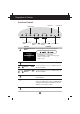
Description of Controls Front Panel Controls SET Button MENU Button SOURCE MENU SOURCE Selection Button DOWN/UP DOWN/UP ( Buttons LEFT/RIGHT ) LEFT/RIGHT ( Buttons Control SOURCE Power Button SET ) Power Indicator Function SOURCE Selection Use this button to select an input signal.
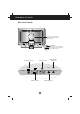
Description of Controls Rear Panel Controls Connected to another object (stand type and wall-mounted type – optional) DC15V D S-Video Video Sound IN L R PC Audio Audio IN L R Locking slot connected to a locking cable that can be purchased separately at most computer stores.
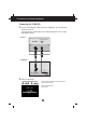
Connecting the Monitor To set up the monitor, ensure that the power is turned off to the monitor, computer system, and other attached devices. Connect the cables to the monitor with it lying on a cushion or a cloth. Follow these steps: Using the Computer 1. Connect the signal cable. When connecting the DVI-D signal cable .....Figure 1 Connect one end of the monitor signal cable to the input connector on the rear panel of the monitor.
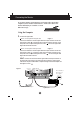
Connecting the Monitor DC Power connector D-sub connector Figure 2 DC15V 3 D S-Video Video IN 1 5 D-sub 2 4 Power Cord AC adapter Signal Cable MAC6 MAC Adapter 2' Signal Cable Note : The figure 2' shows the connection to an Apple Macintosh, using a separately purchased adapter. For more information on adapter requirements, contact your authorized dealer, reseller, or service provider. 2. Connect the plug from the AC adapter into the back of the monitor. 3 3.
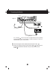
Connection of external equipment Connecting the VCR/DVD 1. Connect the audio/video output jacks of the VCR/DVD to the corresponding input ports of the set. If you connect the S-Video input port to external equipment, you can enjoy high definition display. • Monitor RCA cable (optional) S-Video Video IN Y • VCR/DVD Y S-VIDEO OUT S-Video cable (optional) VIDEO OUT 2. Select an input signal.
On Screen Display (OSD) Control Adjustment Making adjustments to the image size, position and operating parameters of the monitor are quick and easy with the On Screen Display Control system. A quick example is given below to familiarize you with the use of the controls. Following section is an outline of the available adjustments and selections you can make using the OSD. NOTE Allow the monitor to stabilize for at least 30 minutes before making image adjustment.
On Screen Display(OSD) Selection and Adjustment You were introduced to the procedure of selection and adjusting an item using the OSD system. Listed below are the icons, icon names, and icon descriptions of the items that are shown on the Menu. Adjusting the Screen when Using a Computer Note : When input is set as a digital signal, only the BRIGHTNESS, SETUP, and PIP items can be adjusted. You do not need to adjust the other items.
On Screen Display(OSD) Selection and Adjustment OSD Adjust AUTO This function is suitable for analog signal input only. This button is for the automatic adjustment of the screen position, clock and phase. CLOCK To minimize any vertical bars or stripes visible on the screen background.The horizontal screen size will also change. PHASE To adjust the focus of the display. This item allows you to remove any horizontal noise and clear or sharpen the image of characters.
On Screen Display(OSD) Selection and Adjustment OSD Adjust PIP Image RGB PIP ON/OFF OFF Color Position PIP SOURCE V1 ( AV ) PIP SIZE LARGE PIP POSITION Tracking PIP IMAGE Setup PIP Description This PIP (Picture-in-Picture) function allows the image from the VCR or DVD to be displayed on a sub-screen while you are using a computer. PIP ON/OFF To select the sub-screen on/off. PIP To select an input signal for PIP. SOURCE :V1 (AV) / V2 (S) PIP SIZE To adjust the size of the PIP screen.
On Screen Display(OSD) Selection and Adjustment Adjusting the Screen when Using VCR/DVD ( V1 / V2 ) OSD Adjust Description CONTRAST Adjust the display to the contrast desired. ADJUSTMENT Adjustment CONTRAST 53 BRIGHTNESS 70 SHARPNESS 50 COLOR 50 TINT 50 Setup LANGUAGE ENGLISH IMAGE SIZE FULL Setup OSD POSITION TRANSPARENCY BEEP 0 ON SHARPNESS To adjust the clearness of the screen. COLOR To adjust the color to desired level. TINT To adjust the tint to desired level.
Video Memory Modes The display modes listed below are the most commonly used modes and are set as factory defaults. The monitor automatically recognizes most input data modes, and displays centered images with the proper sizing. If the screen size is inappropriately set or the display is not centered, you need to readjust the parameters of the monitor using the OSD (on-screen display). Display Modes (Resolution) Display Modes (Resolution) 1 2 3 4 5 6 7 VESA VESA VESA VESA VESA VESA Horizontal Freq.
Troubleshooting Check the following before calling for service. Display Position is incorrect. Select AUTO in the OSD menu. If the results are unsatisfactory, adjust the image position using the position icon in the on screen display. On the screen background, vertical bars or stripes are visible. Select AUTO in the OSD menu. If the results are unsatisfactory, decrease the vertical bars or stripes using the CLOCK icon in the on screen display.
Specifications Display Sync Input Video Input Type 22inch (55.8cm) Wide SXGA TFT LCD Anti-Glare coating 22inch (55.8cm) 70˚ (Left/Right/Up/Down) 0.294 x 0.294mm 16.7 million color 30kHz - 70kHz (Automatic) 56Hz - 61Hz (Automatic) Separate, TTL, Positive/Negative Digital 15 pin D-Sub connector/DVI-D connector Separate, RGB Analog, 0.7Vp-p/75ohm, Positive Digital Analog : 1600 x 1024 @ 60Hz Digital : 1600 x 1024 @ 60Hz Viewable Size Viewing Angle(max.) Pixel pitch True color Horizontal Freq.