Gateway GT115 Service Guide PART NO.
Preface 1. This Service Guide provides you with all technical information relating to the BASIC CONFIGURATION decided for Gateway's "global" product offering. To better fit local market requirements and enhance product competitiveness, your regional office MAY have decided to extend the functionality of a machine (e.g. add-on card, modem, or extra memory capability). These LOCALIZED FEATURES will NOT be covered in this generic service guide.
Conventions The following conventions are used in this manual : Screen messages Denotes actual messages that appear on screen. NOTE Gives bits and pieces of additional information related to the current topic. WARNING Alerts you to any damage that might result from doing or not doing specific actions. CAUTION Gives precautionary measures to avoid possible hardware or software problems. IMPORTANT Reminds you to do specific actions relevant to the accomplishment of procedures.
Safety, Care and Regulatory Information Before installing a server, be sure that you understand the following warnings and cautions. WARNING: To reduce the risk of electric shock or damage to the equipment: Do not disable the power cord grounding plug. The grounding plug is an important safety feature. Plug the power cord into a grounded (earthed) electrical outlet that is easily accessible at all times. Unplug the power cord from the power supply to disconnect power to the equipment.
Table of Contents PREFACE I REVISION HISTORY I COPYRIGHT I DISCLAIMER I CONVENTIONS II SAFETY, CARE AND REGULATORY INFORMATION III PREVENTING ELECTROSTATIC DISCHARGE III SERVER WARNINGS AND CAUTIONS III TABLE OF CONTENTS 1 MECHANICAL COMPONENTS 4 SYSTEM FRU LIST 6 SYSTEM COMPONENTS 9 SYSTEM SPECIFICATIONS 10 Hardware specification 10 Environmental specification 12 Mechanical specification 13 Power supply specification 14 APPEARANCE OF SYSTEM 16 Front view 16 Rear view
Front Panel LED Description 19 Hard Disk Drive Sequence & LED Description 19 LAN Port LED Description 19 System Block Diagram 21 MOTHERBOARD PLACEMENT AND JUMPER SETTING 22 Motherboard Component 22 Connector Icon Description 23 Motherboard Jumper Setting 24 INSTALLING/REMOVING SYSTEM HARDWARE 25 Chassis Cover Removal and Installation Removing the side cover 26 26 CPU Installation / Removal 27 Cooling Fan Installation / Removal 28 Memory Installation / Removal 29 PCI Expansion Card
Security Menu Setting a System Password Changing a System Password Removing a System Password 49 50 50 50 Server Menu System Information Event Log Configuration 51 52 53 Boot Option Menu 54 Boot Manager Menu 56 Exit Menu 57 TROUBLESHOOTING 58 Error Symptoms List 58 BIOS BEEP CODES 61 BIOS Beep Codes Table PEI Beep Codes DXE Beep Codes 61 61 61 BIOS Recovery Instruction 61 BIOS POST ERROR MESSAGES LIST 64 BIOS POST error message list PEI Phase DXE Phase 64 64 65 UNDETERMINED PROBLEMS
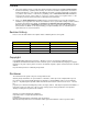
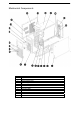
Mechanical Components Item 1 2 3 4 5 6 7 8 9 10 11 12 Description Right side cover System support retainer System bottom plate System support retainer System plastic stands Hard drive cage Hard drive bracket Front door plate Front bezel Power button Bezel lens Power lens 4
13 14 15 16 17 18 19 20 21 22 23 24 Optical drive cage USB bracket USB bracket Left side cover Hard drive slider Hard drive cage Top cover System top cover CD-ROM bracket patch PCI retainer Back cover Rear window 5
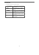
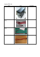
System FRU List Item Photo Chassis Part number HS.31600.004 SATA ODD CABLE 7 PINS, 500MM CA.R4300.001 SATA HDD CABLE 7 PINS, 500MM CA.R4300.002 SAS HDD CABLE CA.31400.
Back I/O SHIELD 33.R7F0L.001 FRONT BEZEL ASSEMBLY TZ.R4300.001 SYSTEM FAN HI.R4300.001 SYSTEM FAN SINK HI.30900.
Main Board MB.R7F0A.001 FSP FSP450-60EP 450W POWER SUPPLY PY.45008.001 Mylar 47.R7F0L.
System components Item 1 Description Front Bezel door 2 Top cover 3 Power supply cage 4 Cooling fan cage 5 PCI card 6 Main board 7 Hard drive blank 9
System Specifications Hardware specification System unit Item Processor socket Processor support Core logic chipsets LAN controller Memory controller Storage controller VGA controller I/O subsystem Memory Description AMD socket C32 Memory Technology – Socket C32 interfaces to DDR3 SDRAM DIMMs. HyperTransport™ Technology. Thermal Monitoring and Control – The Socket C32 processor uses Advanced Platform Management Link.
Memory Item Number of DIMM slots Maximum memory capacity Memory modes Memory controller Description Four 8 GB (2 GB in each of the four DIMM slots) Single DIMM, non-interleaving (DIMM A1) Two DIMMs, interleaving (DIMM A1 and DIMM B1) Four DIMMs, full memory configuration Integrated in the AMD socket C32 processor DIMM specifications Size 512 MB, 1 GB, 2GB, and 4 GB Speed 1066/1333 MHz Type DDR3 Unbuffered ECC DIMM Processor General processor specifications Item Manufacturing technology Descr
Environmental specification Item Temperature range Description Operating 5–35°C (41–95°F) Non-operating -20–60C (-4–140°F) Humidity (non-condensing) Operating 30–80% RH Non-operating 20–90% RH Acoustic noise Full Configuration Sound pressure level in idle mode on bystander position <38 dBA Sound pressure level in full loading on bystander position <45 dBA Light Configuration Sound pressure level in idel mode on bystander position <35 dBA Sound pressure level in full loading on bystander position
Mechanical specification Item System board platform Description uATX (Micro Advanced Technology Extended) System board dimensions Length 304.8mm Width 243.84mm System Dimensions Height 358mm Depth 180mm Width 450mm Server weight (maximum configuration, approximate) Basic configuration (excluding the keyboard and mouse) 8KG Fully loaded configuration (including the keyboard, mouse, and kits) 12.
Power supply specification GT115 supports 300-watts and 450W power supply modules. You have the option to install a 300-watts power supply module or 450W power supply module. Note: If you need to install three hard disk drives, please use 300W power supply (with three connectors). If you need to install four hard disk drives, please use 450W power supply (with four connectors). Item Description Model FSP300-60EP(1) Type 300W Dimensions Height 86 mm (3.38 in.) Depth 140 mm (5.5 in.
Depth 140 mm (5.5 in.) Width 150 mm (5.9 in.) Weight (approximate) 1.43 kg (3.
Appearance of System Front view Item Component 1 USB connectors 2 LED indicator panel 16
Rear view Item Icon Component Description 1 Power supply module cord socket Connect the system power cord here. 2 PS/2 mouse port Connects to a PS/2 mouse. 3 PS/2 keyboard Connects to a PS/2 keyboard. 4 Serial port Connects to serial devices. 5 Monitor port Connects to monitors. 6 Gigabit LAN ports 1/2 Connects to an Internet or intranet network. 7 USB 2.0 ports Connects to USB devices. 8 PCI slot covers Protects to an Internet or intranet network.
Internal Component Item 1 LED indicator Release sliders for the HDD cages. 2 Cooing fan assemblies.
Switch and LED Indicators Introduction This section discusses the different LED indicators located on the : Front panel Hot-plug HDD carrier LAN port Knowing what each LED indicator signifies can aid in problem diagnosis and troubleshooting.
1. Network speed (top) Amber On GbE link network access Green On 100 Mbps link network access Off 10 Mbps link network access 2.
System Block Diagram Channel A 2 DDR3 UDIMMs / RDIMMs Socket Channel B 2 DDR3 UDIMMs / RDIMMs PCI-E x 16 Slot1 PCI-E x 8 Slot2 Intel® PCI-E x 4 Slot3 NB: SR5670 82574L PCI-E x 1Slot4 SATA Port x 6 USB Port x 9 Audio (Option) XGI-Z9S (64MB DDR2) SB: SP5100 TPM (Option) Flash SPI BIOS SIO IT8720 21 Series Port x2
Motherboard Placement and Jumper Setting Motherboard Component This section provides general information on changing jumper settings as well as specific jumper configuration for individual boards in the system.
Connector Icon Description Item 1 Code PS/2 ports 3 VGA port Description Connect to mouse and keyboard. Connect to monitors. 5 7 9 11 13 15 17 19 21 23 25 27 29 31 33 35 USB ports DIMM_2B DIMM_1B CPU_FAN1 SATA4 SATA5 SATA1 CASE_OPEN2 CLR_CMOS1 F_USB1 TPM1 SMBUS_CONN COM2 PCI-E_3 PCI-E_1 ATX_CPU1 Connect to USB devices.
Motherboard Jumper Setting Item 1 Description Clear CMOS jumper (CLR_CMOS1) 1-2 Close: Normal operation. (Default) 2-3 Close: Clear CMOS data.
Installing/Removing system Hardware This chapter contains step-by-step procedures on how to disassemble the server system for maintenance and troubleshooting. To disassemble the Gateway GT115 Server, please pay attention to each section’s instruction and tools needed. NOTE: The screws for the different components vary in size. During the disassembly process, group the screws with the corresponding components to avoid mismatch when putting back the components.
Chassis Cover Removal and Installation Removing the side cover 1. Remove the two screws located on the rear edge of the side panel. 2. Press the side panel release button and slide the side panel toward the rear of the chassis to disengage it. Removing the tower foot 1. Release the bezel door retention tabs from the chassis interior. 2. Pull the bezel away from the chassis.
CPU Installation / Removal The mainboard supports one C32 processor socket with Dual/Four/Six-Core AMD Opteron™ 4100 series. You have the option to upgrade the default processor. Observe the following guidelines when replacing a processor. • • NOTE: Before removing a processor, make sure to back up all important system files. Handle the processor and the HSF assembly carefully. Damage to either may prevent the system from functioning properly.
Cooling Fan Installation / Removal 1. Disconnect the processor cooling fan cable from mainboard. 2. Use a long-nosed screwdriver to loosen the four cooling fan mounting pins. 3. Lift the cooling fan away from the mainboard. 4. Lay down the cooling fan in an upright position - with the thermal patch facing upward. Do not let the thermal patch touch the work surface.
Memory Installation / Removal The motherboard supports DDR3 memory modules, whereby BIOS will automatically detect memory capacity and specifications. Memory modules are designed so that they can be inserted only in one direction. The memory capacity used can differ with each slot. Installation step: 1. Insert the DIMM memory module vertically into the DIMM slot, and push it down. 2. Close the plastic clip at both edges of the DIMM slots to lock the DIMM module.
PCI Expansion Card Installation / Removal Gateway GT115 has four bus slots with of three separate bus segments: • PCI-E_1 -- PCI Express x16 slots • PCI-E_2 -- PCI Express x8 slot • PCI-E_3 -- PCI Express x4 slot • PCI-E_4 -- PCI Express x4 slot with x1 signal Install the expansion card 1. Press the release latch of the slot cover opposite the selected expansion slot. 2. Pull out the slot cover and store it for reassembly later. NOTE: Do not discard the slot cover.
Hard Disk Drive Installation / Removal Below is the instruction of HDD installation and removal SOP. 1. Open the side cover. 2. 3. 4. 5. Note!! Press the release button and pull the blank out of the drive bay. Slide hard disk into blank. Make sure the HDD is seated securely in the HDD blank. Connect the necessary power cable. To connect power cable. Firstly, remove the HDD carrier. Make sure that the drive is properly inserted before pushing the handle back until it clicks into Place.
Power supply installation / Removal The GT115 supports 300 watts and 450 watts power supply modules. The system ships out with only one power supply module installed. Install a hot-swap power supply module 1. Remove the four securing screws from the back of system. 2. 3. 4. Slide toward and lift to remove the power supply module from the system. To install a new power supply module, please reverse the installation step 1and 2. After replacing a power supply module, connect the necessary cables.
Cable Routing Cable Routing image Item Suggest Cable Item Suggest Cable 1 Front switch cable 2 Front USB cable 3 Serial port cable 4 Mini SAS cable 5 SATA cable (onboard SATA to HDD) 6 SATA cable (onboard SATA to ODD) 7 Power cable 8 Case open intrusion 33
BIOS Setup System BIOS BIOS setup is a hardware configuration program built into the system’s Basic Input/Output System (BIOS). Since most systems are already properly configured and optimized, there is no need to run this utility. You will need to run this utility under the following conditions.
Entering BIOS Setup 1. Turn on the server and the monitor. If the server is already turned on, close all open applications, then restart the server. 2. During POST, press F2 If you fail to press F2 before POST is completed, you will need to restart the server. The Setup Main menu will be displayed showing the Setup’s menu bar. Use the left and right arrow keys to move between selections on the menu bar.
Main Menu Parameter Description BIOS Version Version number of the BIOS setup utility. BIOS Build Date Date when the BIOS setup utility was created. Processor CPU Type CPU Core Frequency CPU Count System Time Technical specifications for the installed processor. System Date Set the date following the weekday-month-day- year format. Set the system time following the hour-minute- second format.
Advanced Menu The Advanced menu display submenu options for configuring the function of various hardware components. Select a submenu item, then press Enter to access the related submenu screen.
Processor Configuration Parameter Description Option AMD PowerNow This feature will increase the system battery life, while Enabled delivering performance on demand. It also allows the Disabled processor to dissipate less heat under normal operating conditions, providing a cooler and quieter-running system. MT C1E Enable this feature will let your system utilize the AMD Enabled specific ACPI states to save power consumption.
Microcode Patch Level Processor Microcode Patch Level. CPUID Processor ID number. CPU Stepping Processor stepping information. Processor L1 Instruction Cache Processor first-level instruction cache size detected during POST. An Instruction: to speed up executable instruction fetch. Processor L1 Data Cache Processor first-level data cache size detected during POST. A Data Cache: to speed up data fetch and store. Processor L2 Cache Processor second-level cache size detected during POST.
Memory Configuration Parameter Description Available Memory Total size of system memory detected during POST On-line Spare DIMM Enable this feature will reserve one rank of one logical DIMM to be used as spare rank. This rank will be used when any other rank no longer functions properly. Channel interleaving This feature provides compensating the relatively Enabled slow speed of DRAM. The CPU can access Disabled alternative sections immediately without waiting for memory to be cached.
SATA Controller Configuration Parameter Description Option Onboard SATA Controll When enabled, the SATA controller will function normally. Enabled Disabled OnChip SATA Type Select the on chip SATA type. IDE RAID ACHI IDE: When set to IDE, the SATA controller disables its RAID and AHCI functions and runs in the IDE emulation mode. This is not allowed to access RAID setup utility. RAID: When set to RAID, the SATA controller enables both its RAID and AHCI functions.
PCI Configuration Parameter Description PCI Express Slot 1/2/3/4 When enabled, This setting will initialize the Enabled device expansion ROM for the related PCI-E Disabled slot. Option Onboard Graphics Cont When enabled, the graphic controller will function normally. Primary Video Device Select the primary video device that that the Onboard Video BIOS will use for output. PCIe slot Video Onboard LAN Controller When enabled, the system will enable the onboard LAN devices.
USB Configuration Parameter Detected USB Devices Description Displays the information of installed USB devices in the system. Option USB Controller When enabled, the USB controller will function normally. Enabled Disabled Legacy USB Support Enables or disables support for legacy USB devices. Enabled Disabled Port 60/64 Emulation Enable I/O port 60h/64h emulation support. This should be enabled for the complete USB Keyboard Legacy support for non-USB aware OS.
Legacy Device Configuration Parameter Serial Port 1/2 Device Setting Change Settings Description When enabled allows you to configure the serial port settings. When set to Disabled, displays no configuration for the serial port. Displays Serial Port 1/2 device setting information Option Enabled Disabled Change Serial Port 1/2 device settings. When set to Auto allows the server’s BIOS or OS to select a configuration.
Console Redirection Parameter Console Redirection Description Select whether to enable console redirection. Console redirection enables users to manage the system from a remote location. Option Serial Port 1 Serial Port 2 Disabled Terminal Type Select a terminal type to be used for console redirection. VT100 VT100+ ANSI VT-UTF8 Bits per second Select the baud rate for console redirection. Data Bits Select the Data Bits.
Resolution 100x31 Legacy OS Redirection Terminal data. Enables or disables extended terminal resolution. Enabled Disabled On Legacy OS, the number of Rows and Columns supported redirection.
Power Configuration Parameter Deep Power Off Mode Description Enable or Disable Deep Power Off Mode. Option Enabled Disabled Power On by RTC Alarm Select whether to wake up the system when an RTC alarm is detected. Enabled Disabled Restore on AC Loss Defines the power state to resume to after a sys- tem shutdown that is due to an interruption in AC power. When set to Last State, the system will return to the active power state prior to shutdown.
Hardware Monitor Press Enter to view the Hardware Monitor screen which displays a real-time record of the CPU/system temperature, fan speed, and voltage. Items on this window are non-configurable.
Security Menu The Security menu allows you to safeguard and protect the system from unauthorized use by setting up access passwords. There are three types of passwords that you can set: • Administrator password Entering this password will allow the user to access and change all settings in the Setup Utility. • User password Entering this password will restrict a user’s access to the Setup menus. To enable or disable this field, a Administrator Password must first be set.
Setting a System Password 1. Use the up/down keys to select a password parameter (Set Administrator Password or Set User Password), then press Enter. A password box will appear. 2. Type a password then press Enter. The password may consist of up to six alphanumeric characters (A-Z, a-z, 0-9). 3. Retype the password to verify the first entry then press Enter again. 4. Press F10. 5. Select Yes to save the new password and close the Setup Utility. Changing a System Password 1.
Server Menu Parameter System Information Description Displays basic system ID information, as well as BIOS version. Press Enter to access the related submenu. Event Log Configuration Displays Event Log advanced settings. Press Enter to access the related submenu.
System Information The System Management submenu is a simple display page for basic system ID information, as well as System product information. Items on this window are non-configurable.
Event Log Configuration Parameter Change Smbios Event Configuration View Smbios Event Log Description Press Enter to access the related submenu. Option Erase Event Log Choose options for erasing Smbios Event Log Erasing is done prior to any logging activation during reset. No Yes, next reset Yes, every reset When Log is Full Choose options for reactions to a full Smbios Event Log. Do Nothing Erase immediately Log OEM Codes Enable or Disable the logging of EFI Status Codes as OEM Codes.
Boot Option Menu The Boot menu allows you to set the drive priority during system boot-up. BIOS setup will display an error message if the drive(s) specified is not bootable. By default, the server searches for boot devices in the following order: 1. Hard drive 2. Optical disc drive 3. Removable device 4. Network device 5. UEFI device Parameter Hard Disk Drive Priority Description Press Enter to configure the boot priority.
Bootup NumLock State Enable or Disable Bootup NumLock function. POST Error Pause Select whether to pause POST when a boot-up error is detected. Option ROM Messages Set display mode for Option ROM. Watch Dog Timer Enable or disable Watch Dog Timing function.
Boot Manager Menu The Boot manager menu allows you to specify the boot-up drive. BIOS setup will display an error message if the drive(s) specified is not bootable. Parameter Built-in EFI Shell Description Press Enter to configure the device as the boot-up drive. IBA GE Slot 0100 v1350 Press Enter to configure the device as the boot-up drive. IBA GE Slot 0200 v1350 Press Enter to configure the device as the boot-up drive.
Exit Menu The Exit menu displays the various options to quit from the BIOS setup. Highlight any of the exit options then press Enter. Parameter Save Changes and Exit Description Saves changes made and close the BIOS setup. Discard Changes and Exit Save Changes Discards changes made and close the BIOS setup. Saves changes made in the BIOS setup. Discard Changes Discards all changes made in the BIOS setup Load Default Values Loads the default settings for all BIOS setup parameters.
Troubleshooting Error Symptoms List NOTE: To diagnose a problem, first find the error symptom in the left column. If directed to a check procedure, replace the FRU indicated in the check procedure. If no check procedure is indicated, the first Action/FRU listed in right column is the most likely cause.
4. Main board. Hard disk drive has write error. 1. 2. Enter BIOS Setup and Load default settings. Hard disk drive. Hard disk drive LED fails to light, but system operates normally. 1. With the system power on, measure the voltage of hard disk LED connector. Hard drive LED cable. 2. CD/DVD-ROM Drive NOTE: Ensure CD/DVD-ROM drive is configured correctly in BIOS Setup, cable/jumper are set correctly and its laser beam is clean before diagnosing any CD/DVD-ROM drive problems.
(including blank or illegible monitor). 2. 3. Load default settings (if screen is readable). Main board Parallel/Serial Ports Execute “Load BIOS Default Settings” in BIOS Setup to confirm ports presence before diagnosing any parallel/serial ports problems. Serial or parallel port loop-back test failed. 1. Make sure that the LPT# or COM# you test is the same as the setting in BIOS Setup. Loop-back. Main board. 2. 3. Printing failed. 1. Printer problems. 2. 3. 4.
BIOS Beep Codes BIOS Beep Codes Table PEI Beep Codes # of Beeps 1 1 2 3 3 4 4 7 Description Memory not Installed.
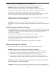
Figure 300-03 62
Recovery Stage 4 Connect the disk, here we use FAT disk and set recovery jumper. Then system would enter BIOS Setup Menu. You may see the page as the following figures shows. 5 Enter “Proceed with flash update” page, the system would recover the BIOS image automically. 6 When recovery process is completed, reset the system.
BIOS POST Error Messages List BIOS POST error message list PEI Phase Status Code Progress Code 0x10 0x11 0x12 0x13 0x14 0x15 0x16 0x17 0x18 0x19 0x1A 0x1B 0x1C 0x1D – 0x2A 0x2B 0x2C 0x2D 0x2E 0x2F 0x30 0x31 0x32 0x33 0x34 0x35 0x36 0x37 0x38 0x39 0x3A 0x3B 0x3C 0x3D 0x3E 0x3F-0x4E 0x4F PEI Error Codes 0x50 0x51 0x52 0x53 0x54 0x55 0x56 0x57 0x58 0x59 Description PEI Core is started Pre-memory CPU initialization is started Pre-memory CPU initialization (CPU module specific) Pre-memory CPU initialization (CP
0x5A Internal CPU error 0x5B Reset PPI is not available 0x5C-0x5F Reserved for future AMI error codes S3 Resume Progress Codes 0xE1=0 S3 Resume is stared (S3 Resume PPI is called by the DXE IPL) 0xE1 S3 Boot Script execution 0xE2 Video repost 0xE3 OS S3 wake vector call 0xE4-0xE7 Reserved for future AMI progress codes S3 Resume Error Codes 0xE8 S3 Resume Failed 0xE9 S3 Resume PPI not Found 0xEA S3 Resume Boot Script Error 0xEB S3 OS Wake Error 0xEC-0xEF Reserved for future AMI error codes Recovery Progress
0x7A – 0x7F 0x80 – 0x8F 0x90 0x91 0x92 0x93 0x94 0x95 0x96 0x97 0x98 0x99 0x9A 0x9B 0x9C 0x9D 0x9E – 0x9F 0xA0 0xA1 0xA2 0xA3 0xA4 0xA5 0xA6 0xA7 0xA8 0xA9 0xAA 0xAB 0xAC 0xAD 0xAE 0xAF 0xB0 0xB1 0xB2 0xB3 0xB4 0xB5 0xB6 0xB7 0xB8 – 0xBF 0xC0 – 0xCF DXE Error Codes 0xD0 0xD1 0xD2 0xD3 0xD4 0xD5 0xD6 0xD7 0xD8 0xD9 0xDA 0xDB 0xDC Reserved for future AMI DXE codes OEM DXE initialization codes Boot Device Selection (BDS) phase is started Driver connecting is started PCI Bus initialization is started PCI Bus H
Undetermined Problems If an error message is present, go to “POST Error Messages List” on page 64. If you did not receive any messages, if the symptom is listed in “or “Error Symptoms List” on page 60. If you still cannot solve the problem, continue with this check: 1. Check the power supply voltages. If the voltages are correct continue with the following steps: 2. Power off the system unit. 3. Perform the following checks, one by one, until you have isolated the problem FRU. 4.